1. Introduction
Optical fibers (hereafter fibers) and fiber-optic sensors based on fiber Bragg gratings (FBGs) are increasingly employed in monitoring and diagnostic systems of fission and fusion facilities. Their compact geometry, immunity to electromagnetic interference, remote interrogation capability, and stability at elevated temperatures make them suitable for harsh nuclear environments. In addition to in-core and fusion-related applications, FBG-based sensors have also been considered for spent nuclear fuel storage monitoring, including distributed water-level and temperature measurements in storage pools [
1]. FBG-based sensors have also been investigated for temperature and strain monitoring in liquid-sodium environments relevant to next-generation sodium-cooled fast reactors [
2]. The need for reliable monitoring technologies is also evident in spent nuclear fuel management, including the long-term dry storage of BN-350 fast reactor spent fuel, where safety assessment requires continued surveillance of sealed storage systems and their radiation conditions [
3]. These examples illustrate the broad interest in fiber-optic and FBG-based sensing technologies for nuclear systems where long-term reliability of both optical and mechanical properties of the sensor is essential.
Numerous studies have demonstrated that radiation-resistant pure-silica fibers with inscribed FBGs remain functional at least up to fast-neutron fluences of 10
19–10
20 n/cm
2 and γ-doses of several GGy [
4,
5,
6,
7,
8,
9]. Most of the previous investigations, however, were focused on radiation-induced optical effects: radiation-induced attenuation (RIA) [
10], radiation-induced luminescence (RIL) [
11], and radiation-induced silica compaction (RISC) [
12]. Recently, Rayleigh scattering coefficient variation during mixed γ–neutron irradiation has also been reported in silica [
5,
13], a phenomenon referred to as neutron-induced opalescence (NIO) [
13]. These studies provide an important basis for the use of FBG-based sensors in nuclear environments; however, the possible radiation-induced effects on the mechanical properties of FBG-based sensors constituted by an FBG embedded in a steel sensor body (“metal-packaged FBG-based sensor”) have virtually been ignored.
Temperature sensing in harsh environments can utilize a fiber with an FBG loosely inserted into a capillary tube without mechanical coupling with the inner capillary wall [
14,
15,
16,
17]. However, in applications requiring strain transfer, vibration monitoring, or reliable attachment to reactor components, the fiber is often mechanically coupled to the sensor body, not loosely inserted into a capillary. The possible sensor body can be metal, glass, or ceramic plates, coatings, and capillaries, which are glued, brazed, or soldered for mechanical protection and reliable operation of the FBG. Up to now, a variety of fiber packaging technologies have been developed and tested [
18,
19,
20,
21], metal packaging being the most promising approach from the standpoint of thermal stability, optical performance, and mechanical robustness. In particular, stable operation of Sn–Bi-bonded aluminum-packaged FBG-based sensors under thermal cycling and strain loading was reported in [
19]. It was also shown that metal-packaged FBG-based sensors can be mechanically suitable under fatigue loading [
20]. These results confirm that metal packaging can be an efficient approach to FBG-based temperature and strain sensing in harsh environments, provided that the packaged sensor assembly demonstrates robustness to reactor irradiation.
Radiation-induced or radiation-assisted changes in metal sensor components may include hardening, embrittlement, changes in local microhardness, phase-dependent degradation, porosity evolution, diffusion-zone modification, or interfacial weakening. These effects are important because, in packaged FBG-based sensors, mechanical reliability depends not only on the fiber or grating, but also on the ability of the capillary, welded regions, brazed filler metal, and stainless-steel sensor body to retain load-bearing capacity after irradiation.
In our previous in-pile experiments [
4,
7,
22,
23,
24,
25,
26], the sensors were irradiated in the cores of IVG.1M and WWR-K reactors, at fast-neutron fluences of up to 4.5 × 10
17 n/cm
2 and 1.8 × 10
20 n/cm
2, and absorbed γ-doses of up to 29.1 MGy and 2.3 GGy, respectively. These papers described in situ and ex situ optical properties of the irradiated fibers and FBGs, including their radiation-induced optical degradation mechanisms and the spectral stability of FBGs written in radiation-resistant fibers. The same irradiation campaigns provide a valuable opportunity to ascertain whether the metal-packaged sensor design retains mechanical integrity after high-fluence reactor exposure.
The objectives of this paper are: (i) to evaluate how high-fluence reactor irradiation affects the mechanical integrity, microstructure, microhardness, and failure behavior of metal-packaged FBG-based sensors, thereby identifying the key factors that can limit their reliability in a reactor environment; and (ii) to develop and validate methodologies for post-irradiation mechanical testing of packaged FBG sensors. So, we investigate the effect of high-fluence reactor irradiation on the material and mechanical properties of FBG-based sensors consisting of Cu-coated FBGs embedded in a stainless-steel sandwich structure and brazed with STEMET-1101 brazing filler metal (BFM). Particular attention is paid to the capillary/welded attachment region and to the multiphase brazed joint, because these regions are expected to control the mechanical reliability of the packaged sensor rather than the intrinsic strength of the FBG itself.
It should be noted that radiation-induced structural changes occurring both in the metallic sensor body and in the glass fiber may affect the Bragg resonance wavelength through changes in grating length and glass density. The radiation behavior of the fibers and bare FBGs employed in these sensors has already been extensively investigated in previous publications [
4,
7,
22,
23,
24,
25,
26,
27]. Additional analysis of Bragg wavelength evolution and other optical effects in the irradiated packaged sensors will be published separately.
3. Experimental Samples, Methods, and Procedures
Upon completion of the irradiation campaigns [
4,
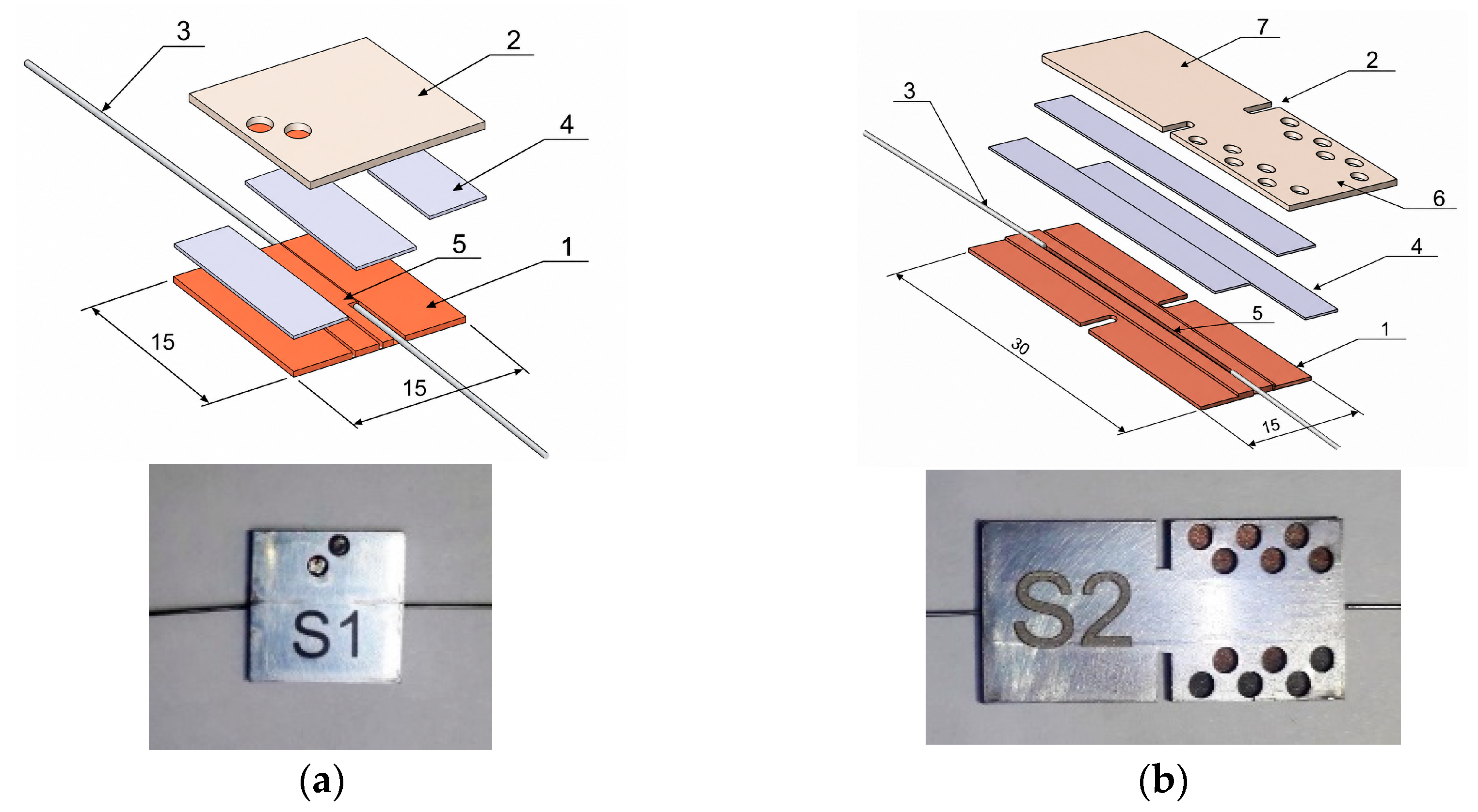
22] and subsequent decay storage, the FBG-based sensors were subjected to a series of post-irradiation examination (PIE) procedures aimed at assessing their mechanical integrity and material condition. The investigated set consisted of 12 sensors, including five sensors irradiated at the IVG.1M reactor, six sensors irradiated at the WWR-K reactor, and one unirradiated reference sensor manufactured using the same fabrication procedure (
Table 2).
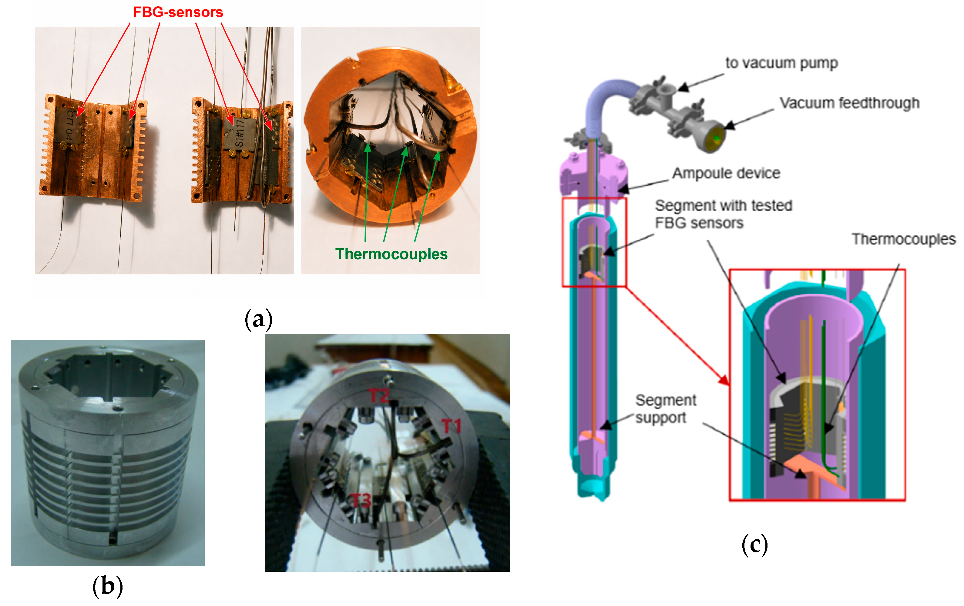
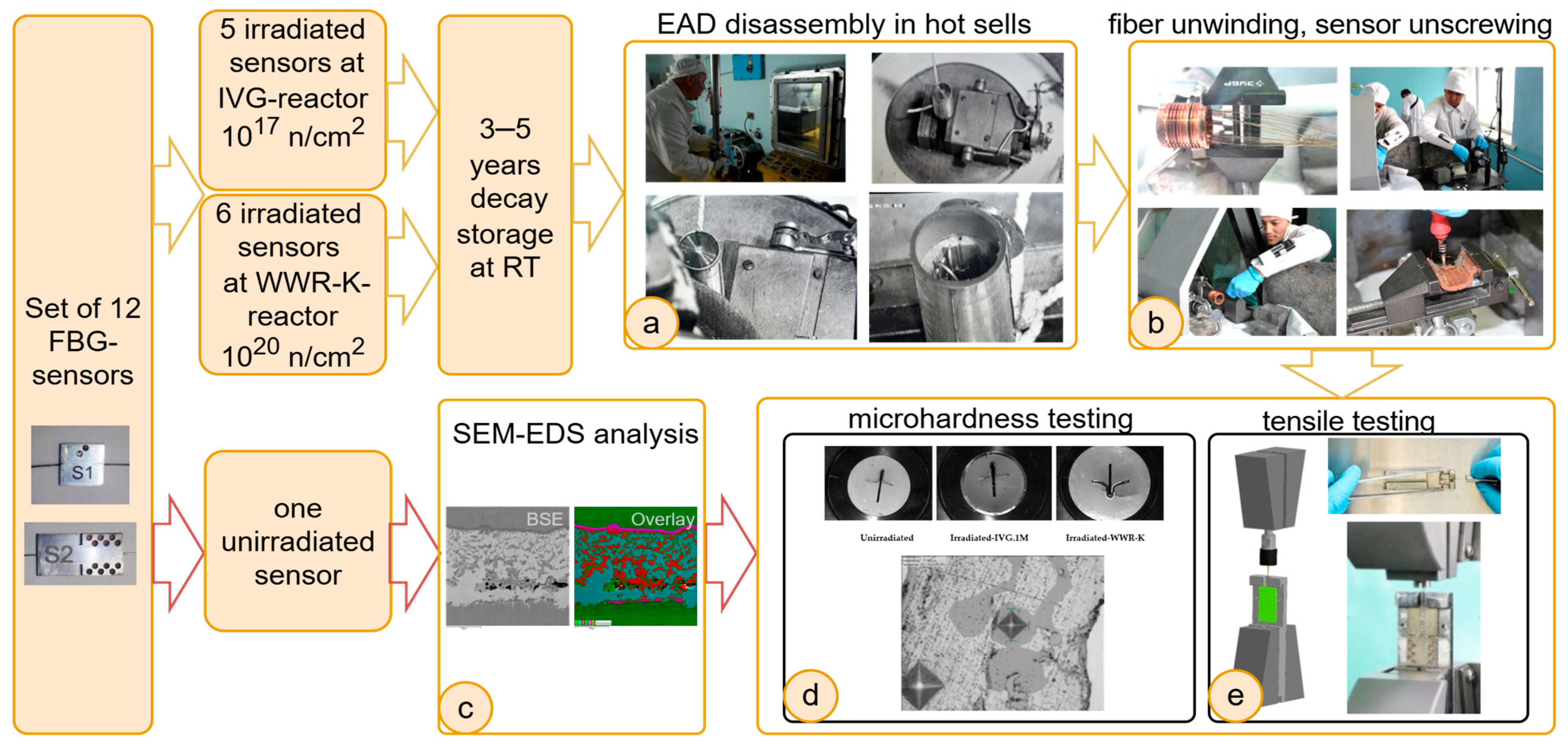
The irradiated sensors remained inside the experimental ampoule devices (EADs) during a decay-storage period of approximately 3–5 years at room temperature (RT). After this period, the EADs were transferred to hot-cell facilities. The overall sequence of post-irradiation examination and testing procedures is summarized in
Figure 3.
3.1. Hot-Cell Disassembly and Sensor Extraction
Figure 3a shows photographs of the EAD disassembly process. Before cutting the EADs, the activated region of the EADs corresponding to the segment location was locally shielded with lead blocks. EAD dismantling started with a circumferential cutting of the tube connecting the upper and lower shells. The EAD lower shell containing the segment with the sensors was then cut inside the radiation-shielded cell using a remote copying-type manipulator under visual control through the shielding glass and with video cameras. Before cutting, the EADs were rigidly fixed in a clamping device. Cutting was performed with a 400 mm diameter cutting wheel at a rotational rate below 600 rpm. Upon completion of the cutting procedure, the segment with the sensors and thermocouples was clearly visible inside the EAD.
The segment was then extracted using a specially designed tool equipped with two hooks. After extraction, three thermocouples were cut off and removed, the further operations being focused on the fiber-optic components. At first, the long fiber lengths were unwound from the external surface of the segment (
Figure 3b). Fiber unwinding was performed manually behind a 100 mm thick protective screen, the segment being rigidly fixed in a vise. During the unwinding procedure, each fiber was temporarily wound onto a separate reel to preserve the original fiber arrangement.
To extract the FBG-based sensors, the segment was dismantled and divided into two structural parts to provide access to the internal surfaces. Each sensor was unscrewed from the segment internal surface (
Figure 3b). All FBG-based sensors were successfully removed without damage and prepared for subsequent post-irradiation examinations.
In disassembling the irradiated IVG.1M EAD, fiber pigtails of sensors S1-117, S2-62, S2-01K, S1-01K, and SP04 (See
Table 2 and Figure 5) were unintentionally cut. These sensors were used in the destructive mechanical testing described below. The remaining sensors with intact fiber pigtails were kept for future post-irradiation optical experiments. A similar disassembling procedure was applied to the WWR-K EAD to provide additional sensors for this investigation (
Table 2).
3.2. Tensile Pull-Off Testing of Capillary
The test object was a capillary attached to one of the steel plates by laser micro-welding. The mechanical strength of the sensor capillary was evaluated using an Instron 5940 series universal testing system (Instron, Norwood, MA, USA) equipped with a 10–50 N high-precision load cell allowing controlled loading of small-scale joints. Each sensor was mounted in custom-designed microgrips (
Figure 3e); the metal capillary was fixed in the upper grip, and the outgoing fiber pigtail was secured in a low-damage clamping fixture to avoid premature fiber breakage. Therefore, the mechanical load was applied to the capillary tube, which in turn applied load to the welded and brazed regions of the sensor assembly. The tests were conducted in displacement-controlled mode at 0.1–0.5 mm/min traverse speed, the capillary being loaded with increasing tension until failure. Tensile tests were performed by loading the capillary until failure. The maximum load, load–displacement curve, and failure mode were registered.
It should be noted that because the tensile experiments are destructive, the same sensor samples could not be tested before and after irradiation. Therefore, comparisons were made between irradiated and unirradiated reference samples, both having been fabricated using the same manufacturing procedure.
3.3. Metallographic Sample Preparation
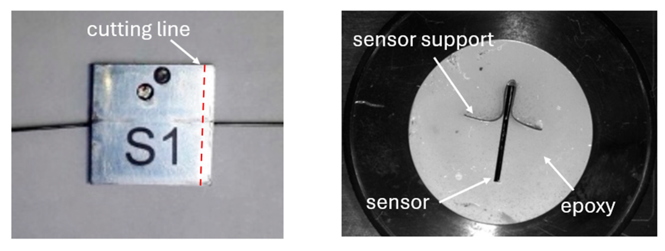
For the metallographic investigations, the sensor body fragments were cut perpendicular to the fiber using an LCQ-100 and G5000 precision cutting machines (Jinan Hensgrand Instrument Co., Ltd., Jinan, China) equipped with abrasive disks and a water-based coolant. Preparation of the metallographic specimen included embedding the fragments in epoxy resin (
Figure 3d), followed by grinding with abrasive papers and final polishing using diamond slurry with particles of decreasing size—3, 1, and 0.25 μm.
Figure 4 shows the cutting line on the sensor body photograph and a metallographic sample thus obtained.
To measure radiation-induced changes in the STEMET-1101 BFM, fragments of the bodies of tensile-tested sensors S1-01K and S1-07K were used.
For comparison, the same unirradiated sensor body was also measured.
3.4. SEM–EDS Microstructural and Elemental Analysis
Unirradiated sensor S1-11 was used as a reference sample for SEM–EDS analysis. The BFM–steel interfaces and capillary regions were examined using a Tescan Vega3 scanning electron microscope (TESCAN, Brno, Czech Republic) equipped with secondary electron (SE) and backscattered electron (BSE) detectors and coupled with an Oxford Instruments X-Act energy-dispersive X-ray spectroscopy (EDS) system with an SSD detector array (Oxford Instruments NanoAnalysis, High Wycombe, UK) (
Figure 3c). SEM imaging was performed in backscattered-electron mode to visualize microstructural changes, porosity formation, and phase segregation induced by neutron–gamma irradiation. The accelerating voltage was 10 kV and the working distance 10–15 mm. The joint morphology, porosity, phase contrast, and possible irradiation-induced microstructural changes were determined with those SEM parameters. Elemental microanalysis, including EDS spectra, maps, and line scans perpendicular to the BFM layer, was carried out at the accelerating voltage of 20 kV and the working distance of 15 mm. These measurements were used to evaluate elemental redistribution, diffusion zones, and possible depletion regions that could influence mechanical integrity of the brazed joint.
3.5. Vickers Microhardness Measurements
To evaluate the irradiation-induced changes in the local mechanical properties of the brazed joint, cross-sectional samples were cut from the sensor bodies. Next, the samples were embedded in epoxy, ground, and polished according to standard metallographic procedures. Measurements were conducted using a Qness Q10A+ automatic microhardness tester (ATM Qness GmbH, Golling an der Salzach, Austria) according to the Vickers method with a diamond pyramid indenter at loads of 50 g and 100 g, which was suitable for thin BFM layers and small diffusion zones. Indentations were made in the STEMET-1101 BFM layer, in the heat-affected zone, and in stainless-steel plates of the sensor body to detect possible radiation-induced changes. Microhardness was evaluated for the primary structural phases of the BFM, including the Cu–Sn phase and the Cu–Ni–Fe–P phase, as well as for the sensor plate material. For each analyzed phase and material region, at least 15 individual Vickers indentations were performed, and the microhardness value was calculated as an average.
4. Results and Discussion
4.1. Tensile Behavior and Failure Modes of Capillary
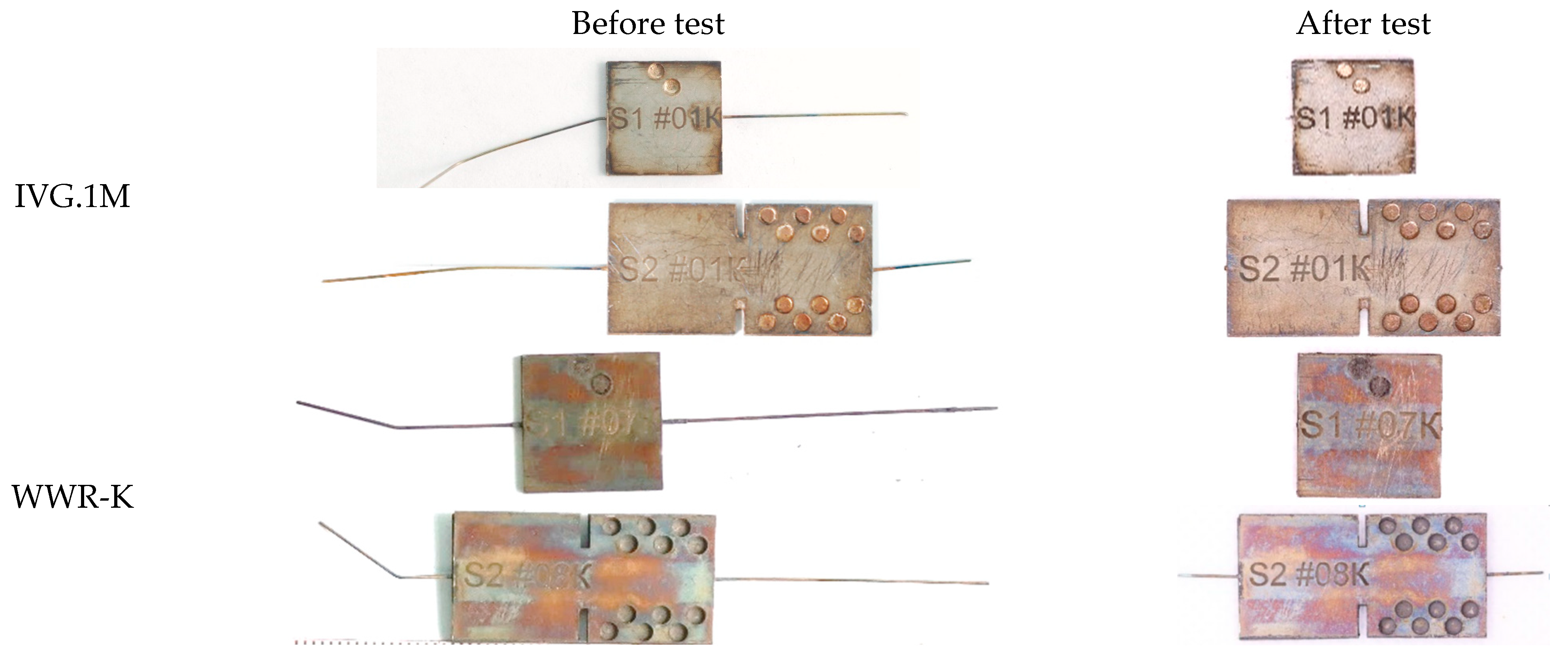
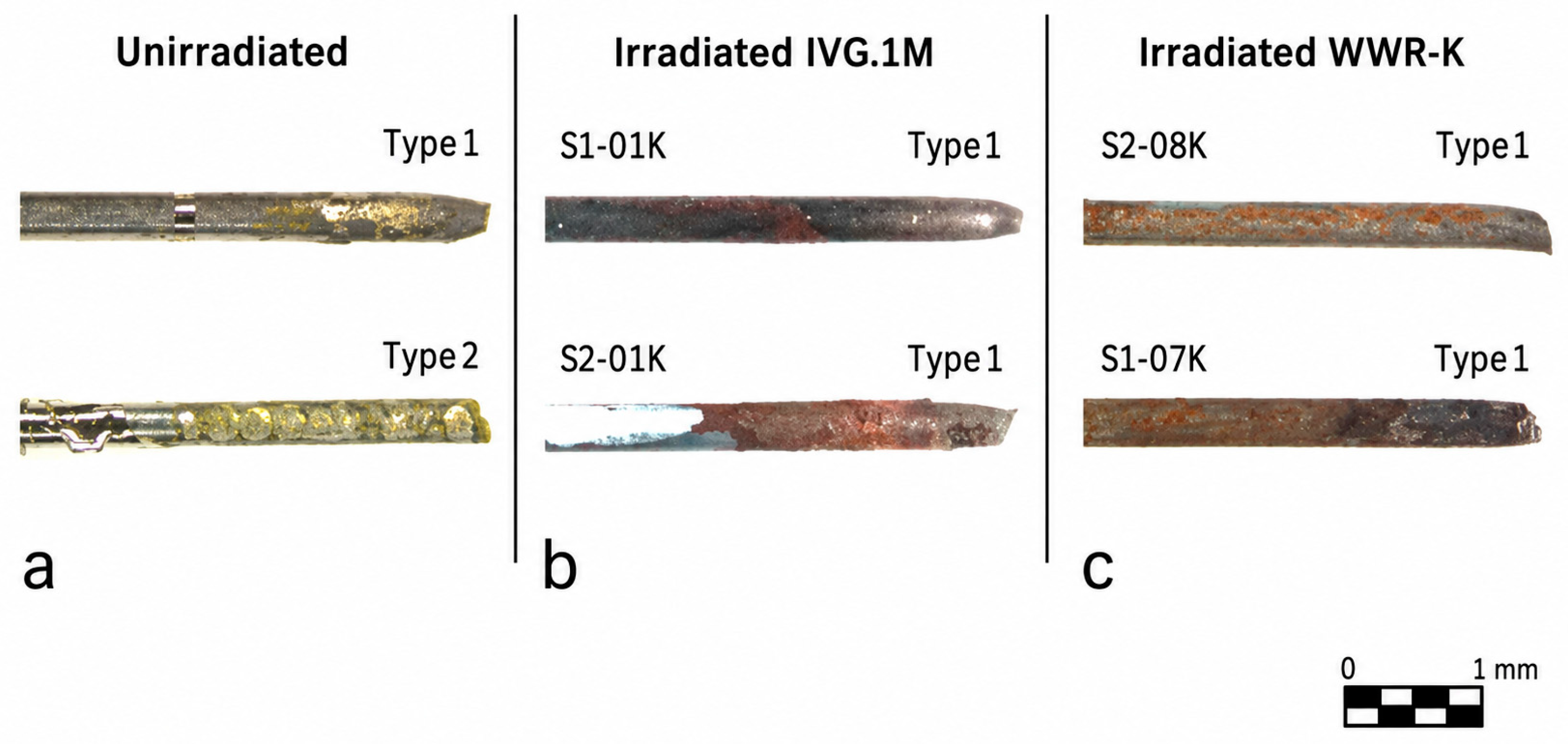
Photographs of the FBG-based sensors irradiated at the IVG.1M and WWR-K reactors before and after the tensile test are shown in
Figure 5. The same sensors were then employed for the investigation of the microstructure and microhardness of the sensor metal parts.
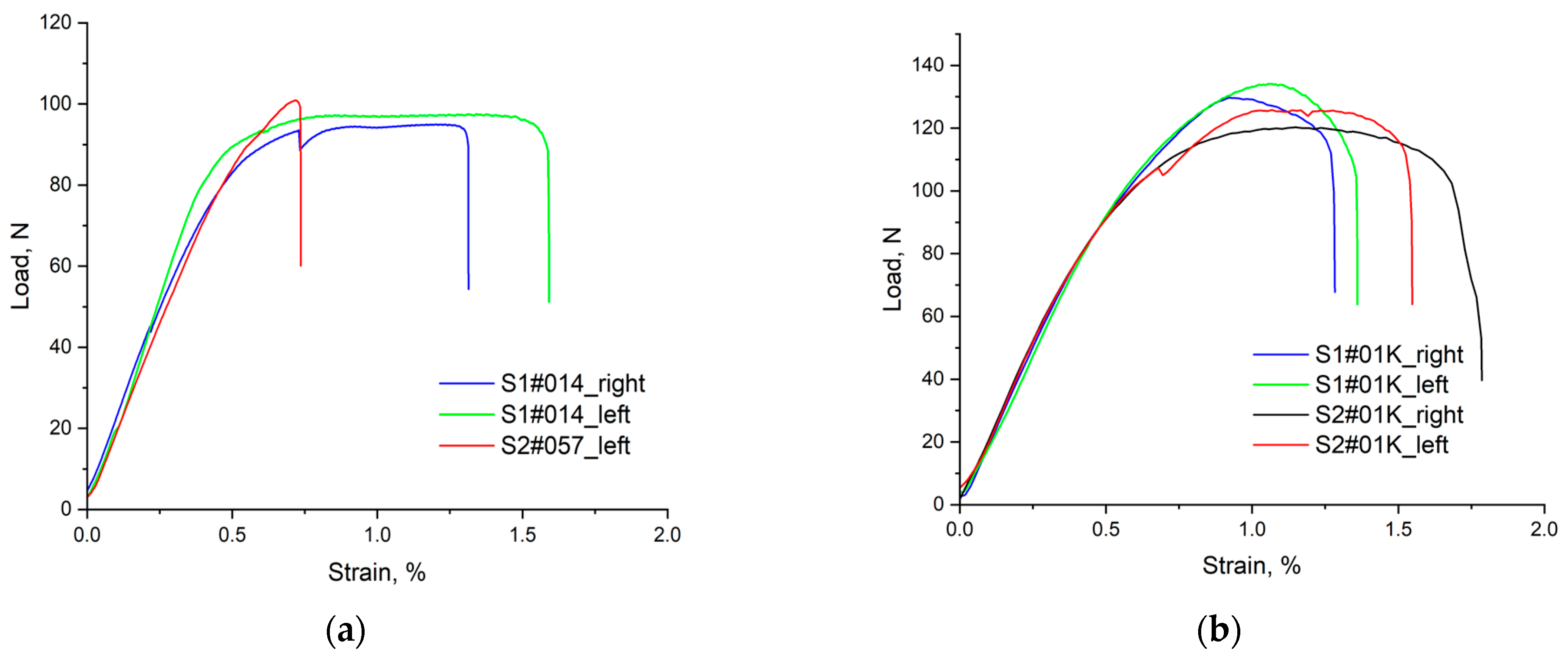
Figure 6 shows the load–strain curves obtained during tests of unirradiated (
Figure 6a) and irradiated (
Figure 6b,c) sensors.
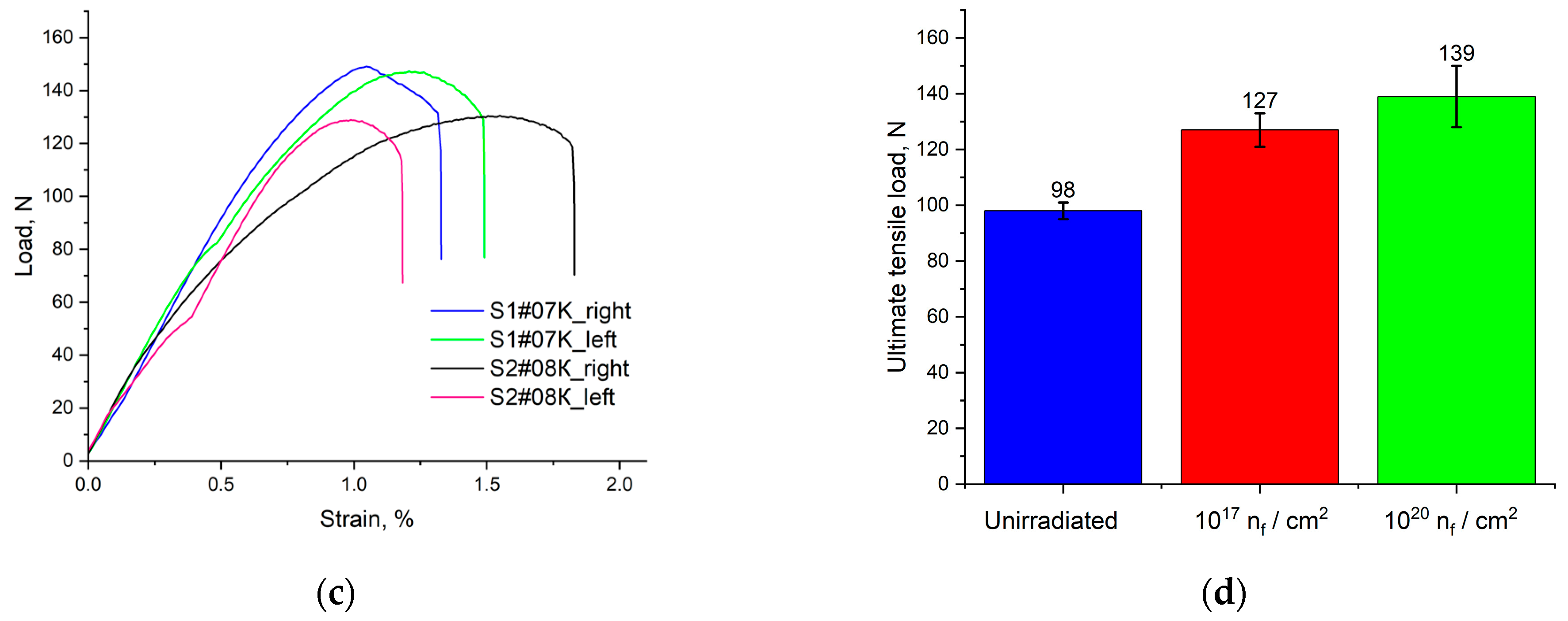
Figure 6d gives a comparison of the mean values of the ultimate tensile load obtained for these sensors.
Note that both the capillary tube and the region where it is attached to the sensor plate were subjected to simultaneous loading. The tensile load was applied directly to the capillary tube, but the load was transferred to the capillary-to-plate attachment region.
In the unirradiated state, the maximum load sustained by the attachment region was virtually comparable to the tensile strength of the capillary tube itself. After irradiation, failure occurred within the capillary tube and at higher loads. Therefore, the observed increase in ultimate load indicates hardening of the capillary tube material, whereas the absence of detachment from the plate indicates that the attachment region conserved sufficient mechanical strength after irradiation.
For interpretation of the tensile-test results, three characteristic failure modes were distinguished. Type 1 corresponds to rupture of the capillary tube away from the laser micro-welded joint; Type 2 corresponds to rupture or fragmentation of the laser micro-welded attachment region; and Type 3 corresponds to partial detachment or damage of the capillary tube near the welded joint due to progressive separation of individual weld spots.
Failure of the unirradiated sensor was mainly due to Type 1 failure, i.e., rupture of the capillary tube away from the welded joint (green curve in
Figure 6a), whereas Type 2 failure, i.e., rupture of the laser micro-welded attachment region, was less frequent. In both cases, the ultimate tensile loads proved to be nearly the same (~100 N), indicating comparable load-bearing capacities of the capillary tube and of the welded joint in the unirradiated state. When failure occurred within the capillary tube wall, localized plastic deformation developed, resulting in the formation of a pronounced necking region before rupture. Some load–strain curves exhibited step-like behavior in both elastic and plastic deformation regimes and were classified as Type 3 failure (blue curve in
Figure 6a). The steps were associated with the detachment of the most strained laser-welded spots located at the edges of the spot-welded region.
In the irradiated sensors, tests revealed a pronounced radiation hardening effect [
31]. With increasing radiation dose, the ultimate load increased to reach 127 N for the sensor irradiated at the IVG.1M reactor (Figure 9b) and 139 N for the sensor irradiated at the WWR-K reactor (
Figure 6c). In addition, after irradiation, the region of plastic strain became wider along the
Y-axis.
It should be noted that, for all tested irradiated sensors, failure occurred within the capillary tube itself rather than in the capillary-to-plate attachment region (
Figure 7). This result primarily indicates irradiation-induced hardening of the capillary tube material. At the same time, the absence of capillary detachment from the stainless-steel plate demonstrates that the attachment region conserved sufficient mechanical strength after irradiation. Thus, the mechanical integrity of the laser-welded capillary–plate joint was not affected by irradiation.
4.2. Baseline Microstructure and Phase Constitution of the STEMET-1101 Brazed Joint
The purpose of this section is to describe the initial microstructure and phase composition of the STEMET-1101 brazed joint in the metal-packed FBG-based sensor. Because structural characterization of the irradiated samples was not be performed, the presented microstructural analysis is limited to the unirradiated condition and serves as a reference for interpreting the microhardness and mechanical behavior discussed in the following sections. Moreover, it appears that it is the initial microstructure of the joint that determines mechanical radiation hardness of FBG-based sensors of the design investigated.
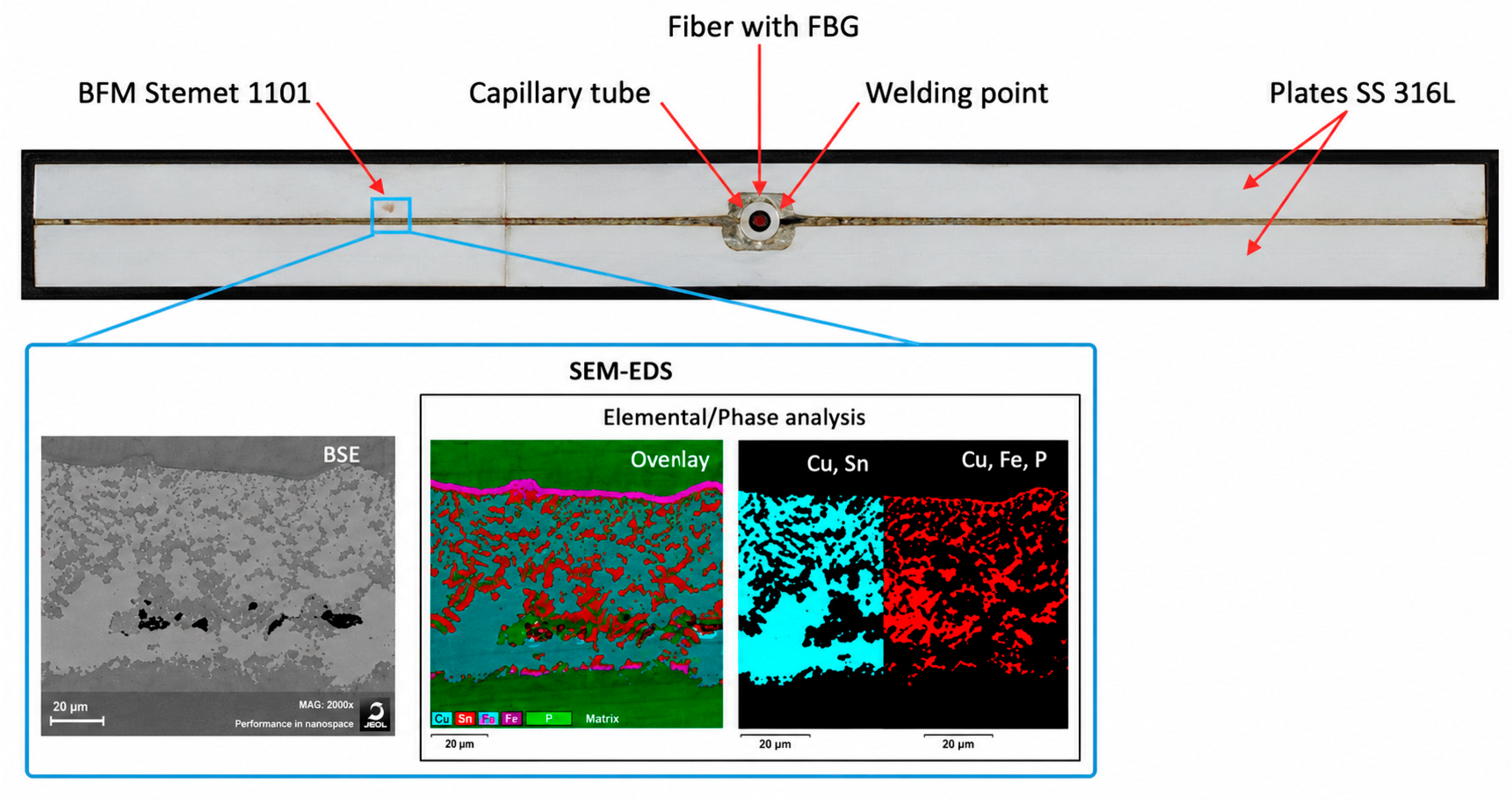
An overview of the sensor assembly and the regions selected for microstructural characterization are shown in
Figure 8.
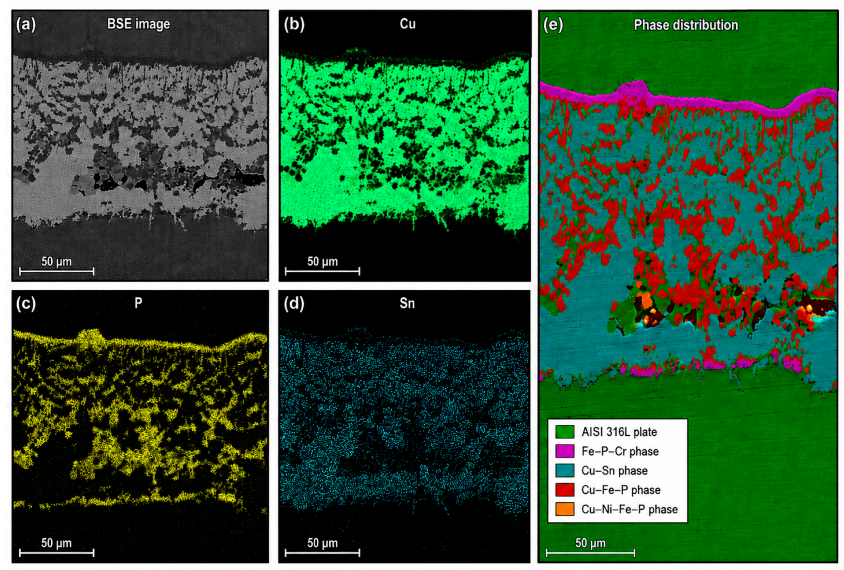
Figure 9.
SEM–EDS analysis and phase distribution of the STEMET-1101 brazed region in the FBG sensor: (a) BSE image of the brazed joint region; (b) Cu elemental map; (c) P elemental map; (d) Sn elemental map; (e) reconstructed distribution of the main phases, including the AISI 316L plate, Fe–P–Cr phase, Cu–Sn phase, Cu–Fe–P phase, and Cu–Ni–Fe–P phase.
Figure 9.
SEM–EDS analysis and phase distribution of the STEMET-1101 brazed region in the FBG sensor: (a) BSE image of the brazed joint region; (b) Cu elemental map; (c) P elemental map; (d) Sn elemental map; (e) reconstructed distribution of the main phases, including the AISI 316L plate, Fe–P–Cr phase, Cu–Sn phase, Cu–Fe–P phase, and Cu–Ni–Fe–P phase.
As shown in
Figure 9, the STEMET-1101 brazed region exhibits a heterogeneous microstructure formed by mutual diffusion between the filler metal and the 316L stainless-steel plate. No sharp interface is observed; instead, a diffusion zone is formed, indicating good metallurgical bonding and extensive mutual diffusion that occurred during brazing. Based on the selected elemental maps and reconstructed phase distribution, four main phases were identified in the brazed region: a Cu–Sn phase, a Cu–Fe–P phase, a Cu–Ni–Fe–P phase, and an Fe–P–Cr phase (see
Table 3). These phases are consistent with previous reports on STEMET-1101 brazing filler metal [
30,
31]. These studies showed that Cu–Ni–Sn–P-based alloys form multiple distinct phases and diffusion zones, which agrees with our observations.
4.3. Phase-Dependent Microhardness Response of Brazed Joint After Irradiation
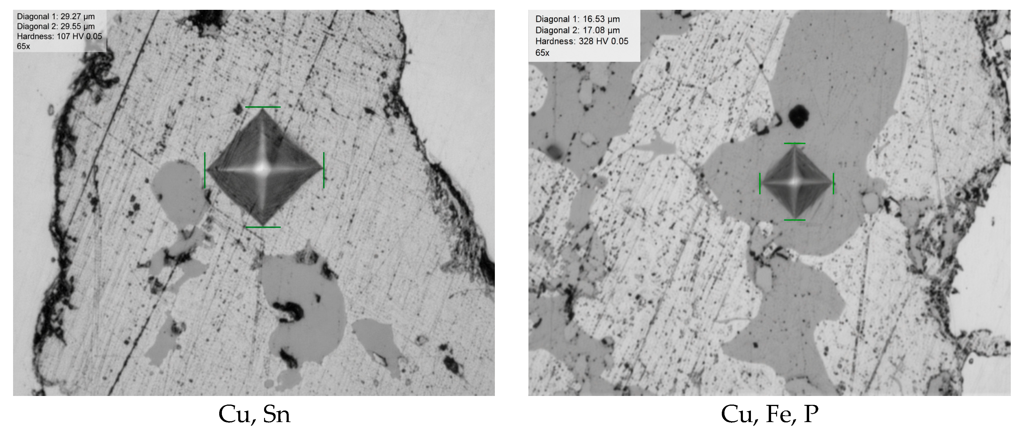
Figure 10 shows diamond-pyramid imprints on individual spots of the Cu–Sn and Cu–Fe–P phases in the STEMET-1101 BFM, whereas
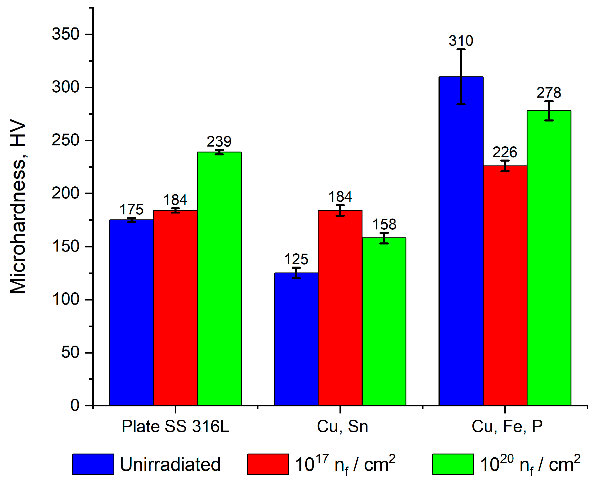
Figure 11 shows the average microhardness for the BFM phases and the sensor plates.
For the sensor plates, microhardness lay in the range from 170 to 248 HV, depending on the sample and irradiation history. For the BFM phases, the microhardness values were 125–184 HV for the Cu–Sn phase and 226–310 HV for the Cu–Fe–P phase.
The measurements shown in
Figure 11 provide quantitative data on the relative hardness of the different BFM phases and sensor plates before and after irradiation. One can see that the Cu–Fe–P phase was noticeably harder than the Cu–Sn phase in all samples, whereas the sensor plates exhibited intermediate microhardness.
A tendency for radiation-induced hardness variation can be noticed in
Figure 11: hardness of the Cu–Sn phase increased after irradiation, whereas hardness of the Cu–Fe–P phase decreased. The sensor plate material (AISI 316L) also exhibited an increased microhardness after irradiation.
The observed changes in microhardness are important because they demonstrate the phase-dependent response of the sensor joint materials to irradiation. The increase in microhardness of the AISI 316L sensor plate is interpreted as evidence of radiation-induced hardening in the austenitic stainless steel. This interpretation is consistent with ref. [
32], where it was shown that fast-neutron irradiation of the austenitic stainless steel at about 250 °C leads to hardening associated with the formation and accumulation of irradiation-induced defects that hinder dislocation motion. Such hardening can increase strength but reduces ductility at the same time.
For the STEMET-1101 brazed joint, the response was not uniform because of its multiphase structure. The increase in microhardness of the Cu–Sn phase after irradiation points to radiation-induced aging or defect-assisted hardening. In contrast, the decrease in microhardness of the Cu–Fe–P phase can be associated with radiation-induced destabilization or partial dissolution of initially hardened phases. In this case, redistribution of Fe and P from metastable precipitates back into the copper-based solid solution can reduce the strengthening contribution of this phase.
Therefore, the microhardness measurements were not intended only to compare numerical hardness values, but to identify possible local hardening or softening of individual phases in the brazed joint after irradiation. This data is important for assessing the long-term mechanical reliability of the packaged FBG-based sensor, because local hardening can increase brittleness, whereas local softening can reduce the load-bearing capacity of the individual phases.
The presence of both hardened and softened phases can also increase local mechanical mismatch within the multiphase brazed region. However, the absence of capillary detachment during tensile testing indicates that the sensor package did retain mechanical integrity.
The results obtained should be considered in the context of previous studies on FBG-based sensors and fibers intended for operation in harsh radiation environments. Those studies demonstrated sufficiently high radiation resistance of fibers and FBGs in terms of radiation-induced optical effects (radiation-induced attenuation, spectral changes, silica compaction, radioluminescence, and neutron-induced opalescence [
4,
5,
6,
7,
8,
9,
10,
11,
12,
13,
22,
23,
24,
25,
26,
27]). Other studies demonstrated the applicability of FBG-based sensors for temperature and strain measurements in radiation environments, including nuclear-fusion-related systems [
1,
2,
14,
15,
16,
17]. A number of works are devoted to metal cladding, metal packaging, fatigue loading, or embedding of FBG-based sensors, but for applications unrelated to radiation [
18,
19,
20,
21]. Those studies did not address any post-irradiation mechanical tests of FBG-based sensor assemblies in metal packaging after high-intensity reactor irradiation. In particular, the mechanical behavior of irradiated capillary fasteners, stainless steel sensor housings, and STEMET-1101 brazed joints remained unstudied. However, this study does provide new experimental data on the mechanical integrity of packaged FBG-based sensors after intense high-neutron-fluence irradiation in a mixed neutron-gamma radiation field.
5. Conclusions
Performance of FBG-based temperature and strain sensors before and after high-fluence mixed neutron-gamma irradiation in the IVG.1M (neutron fluence of up to ~1017 n/cm2) and WWR-K (~1020 n/cm2) reactors was investigated.
Post-irradiation tensile tests showed that the capillary–plate laser welding joints in the FBG-based sensor body retained their mechanical strength, the ultimate tension loads lying in the range of 120–150 N for most samples. The ultimate load for capillary failure increased with radiation doses to reach 127 and 139 N for samples irradiated at IVG.1M and WWR-K reactors, respectively. Most tensile strength experiments showed that failure of the capillary occurred in the capillary itself, not at the welding joint.
The Cu–Fe–P phase of STEMET-1101 brazing filler metal was found to be noticeably harder than the Cu–Sn phase in all samples, whereas the stainless-steel sensor plates exhibited intermediate hardness. Microhardness measurements of the STEMET-1101 brazing filler metal revealed a radiation-induced hardness increase for the Cu–Sn phase and a decrease for the Cu–Fe–P phase. The sensor plate material (AISI 316L) also exhibited an increased hardness after irradiation. These hardness changes are important because the metallic package transfers strain and temperature to the FBG. Irradiation-induced changes in the mechanical properties of the package may modify the strain-transfer coefficient—a key calibration parameter of the sensor—and consequently affect its long-term measurement accuracy and reliability.
The tested sandwich-like structure of the FBG-based metal-packaged sensor was found to possess sufficient mechanical reliability under irradiation conditions relevant to ITER.
Although no failure of the brazed region was observed during the present experiments, the brazed joint remains the most critical part of the sensor assembly. Direct measurements of irradiated brazed-joint strength and long-term thermo-mechanical stability should therefore be addressed in future studies.



 ,
,