1. Introduction
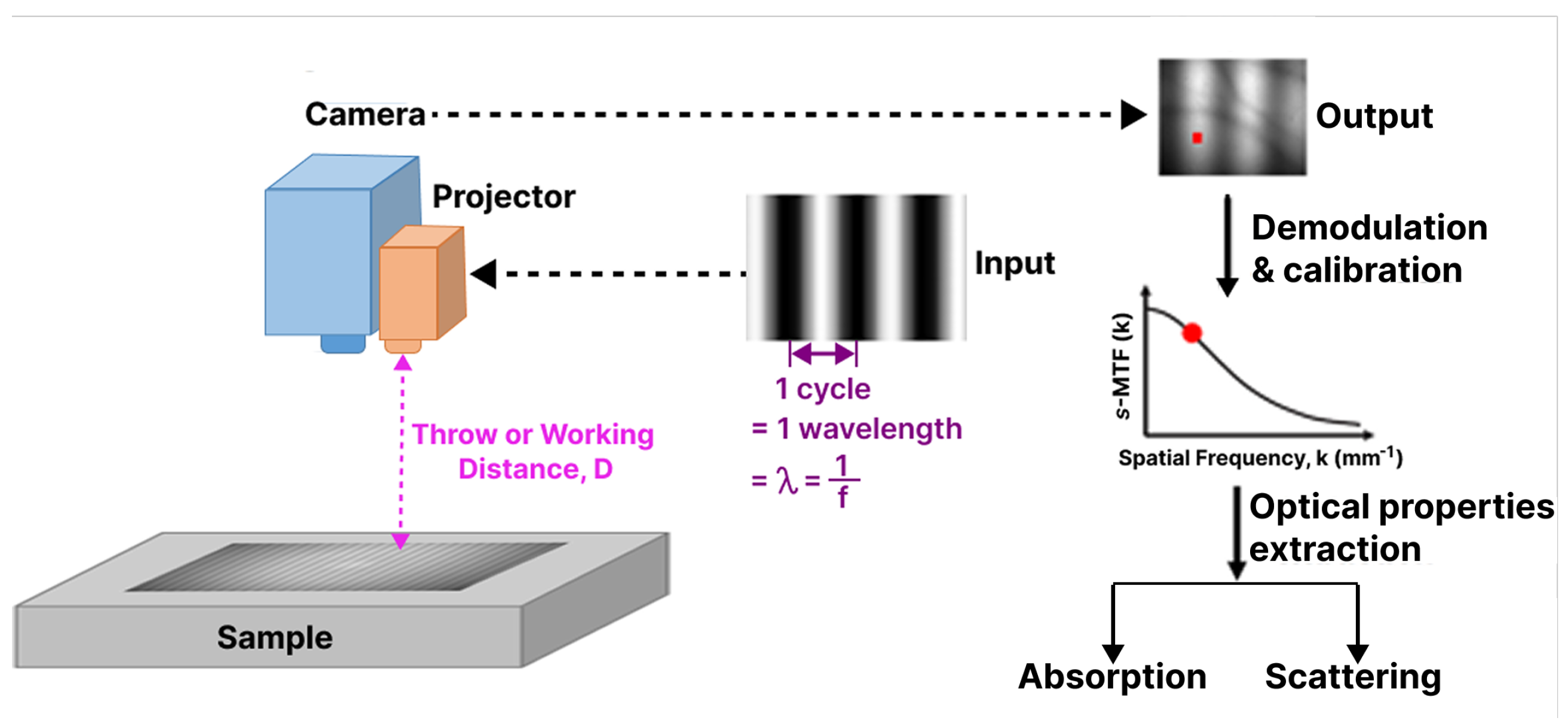
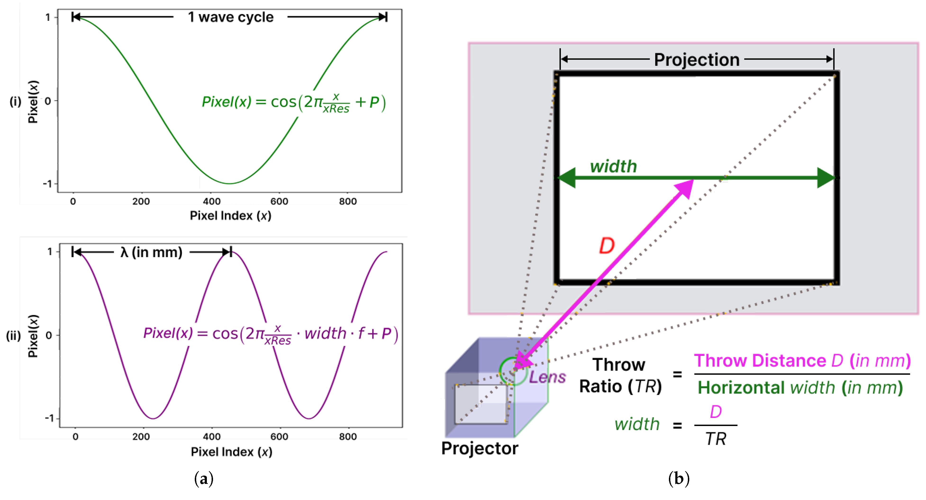
SI is an imaging framework that projects controlled spatial light patterns onto a scene or sample. The captured pattern response is then processed to extract the desired information, such as the surface shape, phase, or optical contrast. SI is widely used because it enables non-contact, wide-field measurement with quantitative information about the target. Common applications based on SI include fringe projection profilometry to extract 3D surface information from an object [
1] and SFDI for optical-property imaging [
2].
In fringe projection profilometry, sinusoidal fringe patterns are projected onto an object. The deformation of these fringes is used to recover the surface shape of the object [
1]. In SFDI, sinusoidal patterns with different spatial frequencies are projected onto a turbid sample, and measured reflectance is used to estimate absorption and reduced scattering properties [
2,
3]. Although these fields measure different physical quantities, both use controlled illumination patterns and phase-based decoding. A common method used in these SI fields is TPS, also known as TPD in SFDI [
2]. In TPD (i.e., TPS), three sinusoidal patterns projected onto a sample or scene are captured with phase shifts of 0,
, and
. These three images are then combined to remove background brightness, and the useful fringe variation is kept for the recovery of the phase or the amplitude of the spatially modulated reflectance [
4,
5].
As discussed earlier, SFDI is an SI technique in which the capture of three phase-shifted patterns (i.e., TPD) is one of the most important acquisition steps for optical-property recovery. Real-time projection and acquisition for TPD are often desired for use cases in fields such as medicine (e.g., in surgical settings) [
6]. TPD requires multiple sequential images for a single measurement, which increases acquisition time and makes the result highly dependent on accurate projection–capture synchronization. In TPD, each camera capture must be synchronized with its corresponding projected phase pattern. If the camera is triggered too early or is out of sync with the projector phase change, the captured images may not correspond to the intended phase shift. This phase–capture mismatch reduces demodulation accuracy and can introduce artifacts (
Section 2.2). Hence, TPD-based SI systems impose strict requirements on projection–capture synchronization, system latency, and deterministic timing. In addition to timing performance, SI systems also require a suitable system-level design. A real-time SI platform should support high-frame-rate acquisition with low latency while maintaining a compact, portable, and modular form factor. Such a design improves flexibility, simplifies integration, and supports deployment in space-constrained experimental or applied environments. Compatibility with standard interfaces, such as USB-based cameras and HDMI-driven projectors, is also important because it improves interoperability and reduces system complexity. Motivated by these performance and design requirements, the primary objective and contribution of this study is to investigate and develop a real-time SI system for the TPD method. The proposed work focuses on deterministic and low-latency synchronization between projection and capture while maintaining a modular and compact system architecture. Therefore, the scope of this study is explicitly limited to the system-level design, implementation, and validation of the synchronization framework.
In this study, the SOTA SFDI literature is particularly relevant for three main reasons. First, SFDI is a well-established SI technique in which conventional TPD is commonly used to achieve high-fidelity optical-property recovery. However, this study does not focus on quantitative optical-property extraction and analysis. Such analysis requires a fully validated and stable SI acquisition system as the first necessary step. Therefore, this study first establishes and validates the synchronization-based SI platform, while optical-property analysis is reserved for future work. Second, this work begins by studying an existing SOTA system: the HSPy-SI system [
7]. This system was developed for SI-based imaging and was designed to accelerate TPD by using an HS snapshot camera. The system is briefly introduced later in this section and discussed in further detail in
Section 3. In this study, it is used as a benchmark to evaluate the runtime performance of the proposed SI system. Third, the SFDI field has already introduced real-time alternatives to conventional TPD-based imaging, such as SSOP [
8]. SSOP uses only one sinusoidal image instead of three phase-shifted images. This reduces the acquisition requirement and enables real-time imaging. However, this speed improvement comes with important trade-offs. Since SSOP estimates modulation from a single image, it can suffer from lower spatial resolution, reconstruction artifacts, edge artifacts, and reduced image quality compared with conventional TPD-based SFDI [
8,
9,
10].
Therefore, the SOTA SFDI literature provides a suitable comparison set for this study. Beyond the primary benchmark (i.e., HSPy-SI system), reported SSOP results from the literature are also considered as a secondary reference point. This additional comparison places the proposed system within the broader context of real-time SFDI methods. Since SSOP is not implemented in this study, the comparison is limited to previously published results by other authors (Table 2). And finally, the experimental results obtained using the proposed system are used to discuss the trade-off between its acquisition speed and demodulation quality (Figure 20 in
Section 5.5.14).
The development of SFDI has been accompanied by the evolution of different hardware and implementation designs, tailored to meet the different requirements of specific applications. Regardless of the application, SFDI instruments require three basic components: a light source, a spatial light modulator to generate light patterns, and a camera to capture images. Furthermore, most SFDI systems use two crossed linear polarizers between the light source and the detection system to reduce specular light. Digital micromirror devices (DMDs) are the main technology used to project spatial frequency patterns for SFDI applications; these devices are composed of two-dimensional arrays of mirrors that can be individually controlled to an on- or off-state [
11]. In the on-state, the mirrors reflect the incoming light through projection optics, thereby providing light in the projection. In contrast, in the off-state, light is directed elsewhere. Most SFDI systems use DMDs [
2,
12,
13], but they take time to switch their micromirrors on and off, so switching an 8-bit sine-wave pattern typically takes 40 ms [
14]. This process can introduce variable projection latency, which in turn affects the total data acquisition time. Lowering the bit depth of the patterns can increase the DMD frame rate [
15]. As an alternative, applying Fourier domain demodulation to coherent SFDI achieved 50 FPS in real time by using static film masks with printed sine waves instead of a DMD and without an HS camera [
16,
17,
18]. For the detection systems used for SFDI systems, monochromatic cameras are commonly utilized to detect light intensity. These typically use spectral filters such as liquid crystal tunable filters (LCTFs) in conjunction with LED illumination systems to acquire images at specific wavelengths [
19]. Although they are simple to use, the sequential band acquisition of LCTFs can limit temporal resolution. Thus, to reduce the acquisition time, researchers often decide to reduce the number of wavelengths to measure, taking ≈50 s [
19], 13 s [
20], 12 s [
21,
22], and even 3.6 s [
23] to gather the desired wavelengths and spatial frequencies. To further increase the spectral information measured, another approach consists of using HS line scan cameras, but it can take ≈5 s to scan one phase [
24]. To address scanning issues, HS snapshot sensors were used to capture spatial and spectral information in a single exposure time. Although HS snapshot sensors have not been extensively reported when applied to SFDI, Strömberg et al. [
25] developed an SFDI system to evaluate HS snapshot cameras. However, their study revealed that the performance of the HS snapshot camera in getting optical properties was highly dependent on illumination and wavelength selection.
In conjunction with the interest of the research community, the development of SFDI has led to the emergence of commercial systems based on SFDI. The first company to develop a commercial research SFDI system was Modulim (Irvine, CA, USA), previously known as Modulated Imaging Incorporated, whose SFDI system for research purposes was named Reflect RS
TM, whose first prototype was used for a preclinical study with porcine models [
26]. The Reflect RS
TM can be programmed to measure at any spatial frequency but typically measures 10 wavelengths at five spatial frequencies, and it also accounts for height- and angle-dependent reflectance changes using well-known techniques reported in the literature [
27]. The projection and acquisition of all these spatial frequencies for each wavelength in three phases takes ≈54 s for a complete data acquisition. Recently, Modulim commercialized a faster SFDI system named Clarifi
®; however, it uses five LEDs for homogeneous illumination and only a single spatial frequency of 0.12 mm
−1 at 850 nm, requiring approximately 10 s to acquire all data [
28]. The utilization of LEDs for illumination in SFDI-based systems has become a prevalent practice among researchers in this field. Moreover, open-source online resources have recently been published on the subject of designing a low-cost SFDI system with three LEDs [
29].
Despite the progress in commercial and low-cost SFDI systems, conventional TPD-based acquisition remains limited by the need to capture multiple phase-shifted images for each wavelength and spatial frequency. As the numbers of wavelengths and spatial frequencies increase, the total acquisition time also increases, which limits real-time performance and increases sensitivity to synchronization errors. To overcome this limitation, SSOP evolved as an alternative to conventional TPD-based SFDI systems. Early proof-of-concept studies showed that SSOP could achieve real-time optical-property imaging, operating at rates faster than 25 images per second, while maintaining high accuracy, with a margin of error less than 10% compared to SFDI [
6]. However, this speed advantage comes with important trade-offs compared with the conventional TPD-based method. Since SSOP relies on only one captured image instead of multiple phase-shifted measurements, it initially suffered from reduced image resolution and visible reconstruction artifacts [
8,
9]. Although the method has been progressively refined over time to improve reconstruction quality and overall performance, current SOTA SSOP implementations still exhibit edge artifacts, provide lower spatial resolution than conventional SFDI, and do not incorporate sample profile correction [
10]. These limitations reduce its suitability for clinically demanding applications, where high reconstruction fidelity and robust handling of tissue geometry are important. Although additional correction and compensation strategies can be introduced to mitigate some of these issues [
6], they also increase computational overhead and add further algorithmic and system-level complexity. A temporally modulated SSOP variant has also been reported, achieving a raw video acquisition rate of 55.6 frames/s by recording a continuous sequence and separating wavelength channels through temporal FFT before applying SSOP reconstruction [
30]. This improves speed relative to conventional TPD-based SFDI because it avoids sequential phase-shifted captures during acquisition. However, the gain in frame rate comes with a trade-off: the method depends on multi-frame temporal demodulation and subsequent SSOP processing, rather than delivering a direct high-quality single-frame optical-property estimate. As a result, despite faster acquisition, its applicability remains limited by reduced reconstruction fidelity, motion sensitivity, and lower image quality than conventional TPD-based SFDI.
Desktops are commonly used to generate patterns or to connect detection and projection systems [
12,
26,
29], and microcontroller units (MCUs) have even been employed to interface the camera with the DMD [
31] or to actuate mechanical elements for static-film displacement [
16,
17]. The absorption-reduced surface fluorescence imaging (ARSFi) method employed high-spatial-frequency SFDI using a LightCrafter evaluation module in pattern-sequence mode, reaching up to 19 FPS; however, it did not use an HS camera and remained dependent on the specific Digital Light Processing (DLP) projector model [
32]. Importantly, and to the best of our knowledge, previous studies have not explored the use of an SBC-SoC development board combination to achieve real-time projection–capture synchronization. Furthermore, embedded boards offer a smaller form factor than desktop-based control hardware, which can improve system portability. They can also preserve interoperability through standardized interfaces (e.g., USB, HDMI) that simplify integration. One way to reduce the time taken to acquire spatial and spectral information is to use HS snapshot cameras and broadband illumination with lamps. This would eliminate the need for the spectral filtering done in LCTF systems and would even project the same pattern at different wavelengths using LEDs sequentially, thereby reducing acquisition time. Moreover, another fundamental aspect of correctly acquiring patterns in SFDI is ensuring that the camera and projector are synchronized correctly, which ensures the acquisition of data without artifacts for further data processing.
This research begins by studying an existing SI system known as the HSPy-SI system. It is a desktop-based projection–capture synchronization system comprising a DLP projector [
33] and a Ximea HS snapshot camera [
34] submodule. As the primary contribution, this study introduces HyperSI, a newly proposed synchronization system that reuses the projector and camera submodules from the existing setup and has been designed to address the limitations of the HSPy-SI system. The HSPy-SI system is considered SOTA, as it was developed in accordance with the foundational methodologies established by leading research in the SFDI field. It follows the conventional TPD method (
Section 2, Figure 1) originally introduced by Cuccia et al. [
12] using a DMD-based DLP projector. It can measure multiple wavelengths at a given spatial frequency, as in the early prototypes of SFDI commercial systems [
26], and employs an HS snapshot camera instead of monochromatic cameras to avoid spectral filtering through external elements such as LCTFs, enabling faster acquisition of projected patterns at multiple wavelengths within one exposure time, as done by Strömberg et al. [
25]. The HSPy-SI system uses the DLPLCR4500EVM projector in video mode with 24-bit RGB pattern HDMI input [
33] from its own pattern generator. DLP projectors that support video mode with HDMI pattern streaming are highly versatile for projection–capture synchronization because they operate using a standardized high-quality 24-bit RGB frame-based pipeline [
33,
35,
36,
37]. Hence, they can work with maximal default settings for the video mode with minimal user intervention (e.g., only disabling gamma correction). HDMI input ensures consistent timing, format, and resolution between devices, eliminating the need for model-specific memory mapping or custom command protocols. All HDMI specifications (e.g., 1.1, 1.3, 1.4, 2.2) include an embedded
VSync signal, which allows an external frame generator to lock to the frame rate of the projector.
VSync is a signal that indicates the end of one frame and the start of the next in a video stream; this ensures predictable and repeatable pattern timing. Furthermore, unlike the pattern sequence mode of the projector, the HDMI video mode streams patterns continuously, supporting real-time synchronization for structured light and other fast projection–capture applications. However, different projector models offer varying default sets of supported pattern resolutions due to the specific versions of the DMD and controller they use. For example, DLPLCR4500EVM supports
and
[
33], DLP3000DMD supports
[
35], and models such as DLPLCR900EVM [
36], DLPLCR90EVM and DLPLCR65EVM [
37] support up to
. These resolution differences can be accommodated by the pattern frame generator within the synchronizer, as handled by the HSPy-SI frame generator for the
resolution. Therefore, a projection–capture synchronizer can be considered DLP-projector-agnostic for projector models that support video mode with a continuous high-quality 24-bit RGB pattern stream via the HDMI interface. Furthermore, the synchronizer can be considered snapshot-camera-agnostic when using cameras with a USB interface, since they can be integrated by managing the appropriate drivers. Vendors such as Ximea provide their own drivers to enable high-speed capture and advanced features. Alternatively, UVC (USB Video Class)-compliant snapshot cameras represent a more general USB-supported option, as they rely on a standardized driver layer on top of the core USB driver to ensure consistent basic functionality across different imaging systems. However, the Ximea HS snapshot camera is chosen as the candidate in this work because the SOTA HSPy-SI system uses the same model.
Although the HSPy-SI system provides a solid foundation and adheres to established SFDI methodologies, it is constrained by its inability to support continuous real-time acquisition. It is limited to performing only three modulated captures followed by a demodulation per cycle. Furthermore, it cannot achieve frame-accurate projection–capture synchronization due to its lack of dynamic control over the individual pattern frame generation. These factors increase system complexity and introduce real-time performance bottlenecks. In addition, the desktop form factor reduces the overall portability of the system. Hence, these limitations motivate the development of a high-performance, real-time bench-top SI synchronizer system, whose contributions are as follows: (i) providing a methodology to generate high-quality 24-bit RGB modulated patterns with high performance, such as ≈60 Hz; (ii) supporting model-agnostic frame transport to DLP projectors over HDMI in video mode; (iii) enabling camera-agnostic acquisition via standard USB snapshot cameras (i.e., USB3 HS snapshot cameras); (iv) achieving frame-accurate projection–capture synchronization using a tunable synchronization parameter; and (v) maximizing both demodulation quality (i.e., free of artifacts or noise) and runtime performance. A review of existing SOTA approaches [
14,
16,
17,
18], including the HSPy-SI system, reveals several strategies that have been employed to address real-time performance challenges in SFDI. In addition, further research was conducted to explore additional methods to improve real-time performance. To achieve high-quality pattern generation, projector and camera agnosticism, accurate synchronization, and good demodulation and runtime performance, the following methods are considered candidates for the proposed system:
Load the patterns into the flash memory of the DLP projector and trigger the change of patterns using a computer or an MCU [
19,
29,
38].
Reduce the bit depth of the patterns on the DLP projector [
14].
Use static film masks with printed sine waves instead of using a DLP projector [
16,
17,
18].
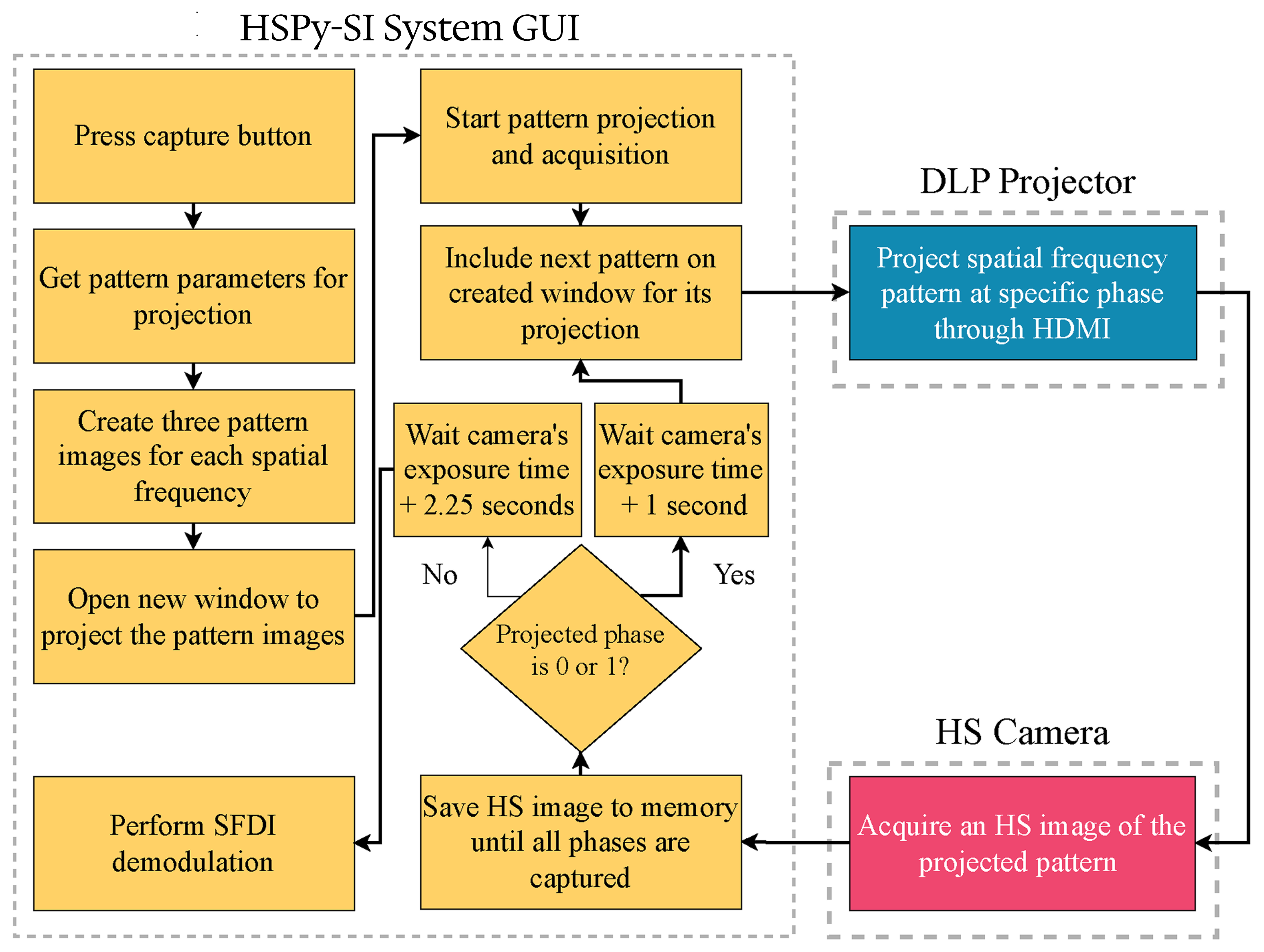
Introduce a fixed-time waiting period between pattern changes and HS camera capture, as done in the SOTA HSPy-SI system.
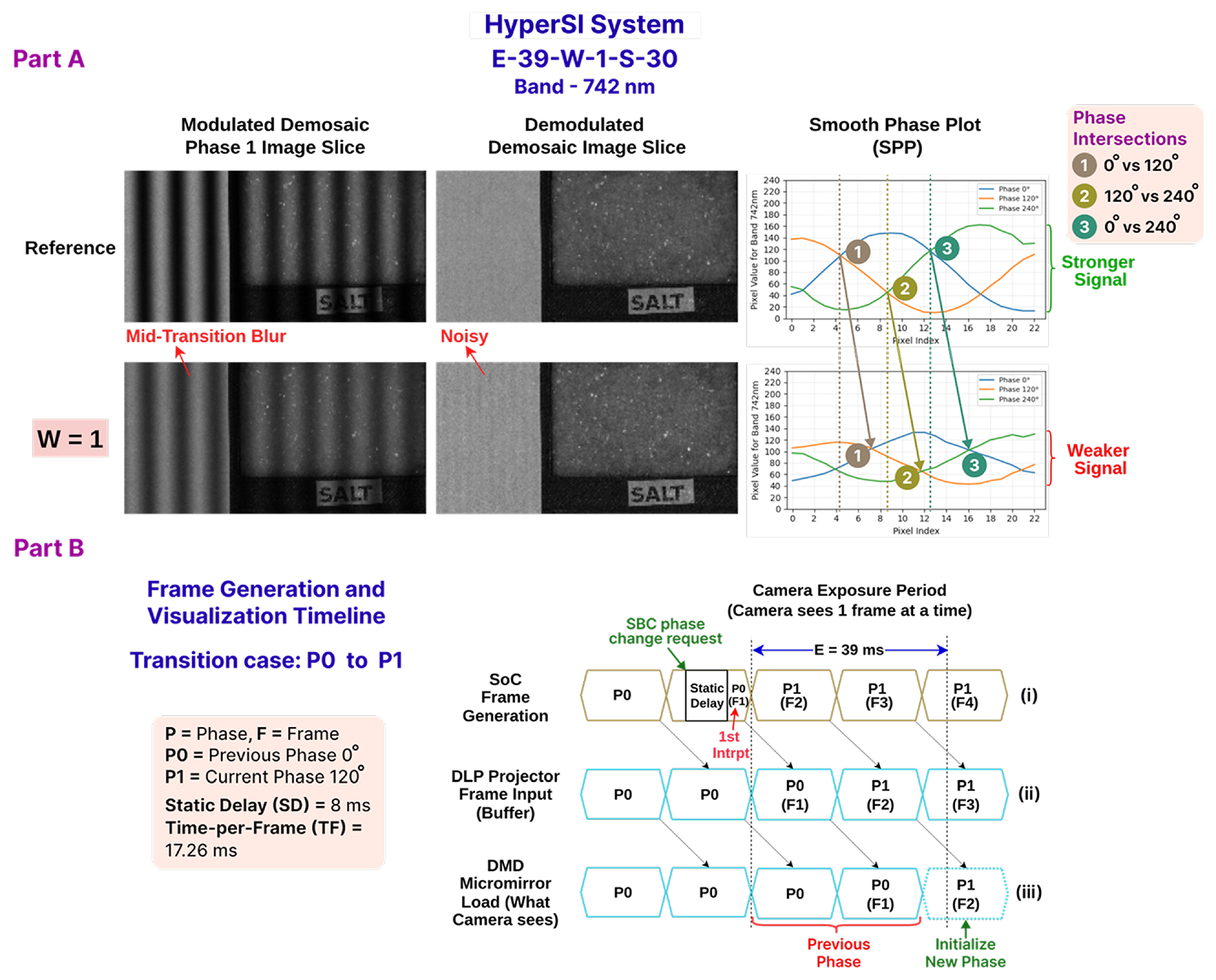
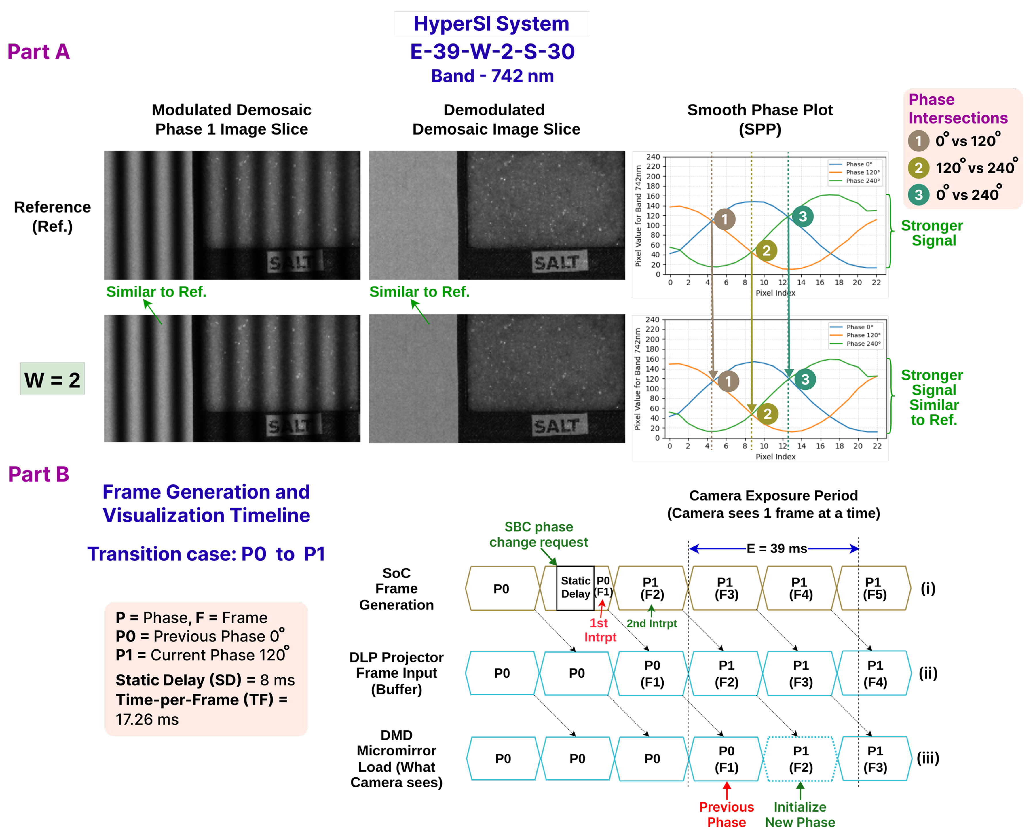
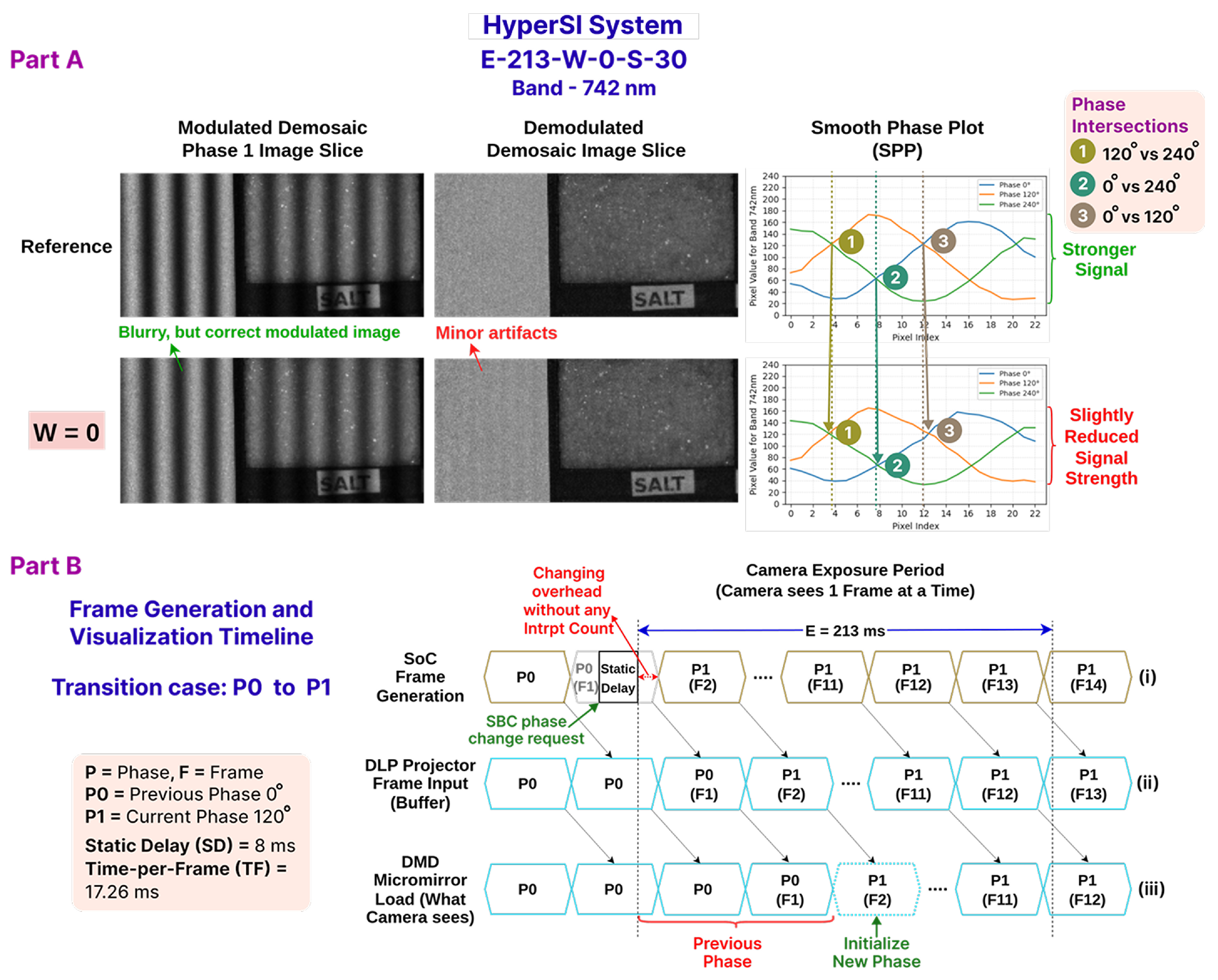
Introduce a tunable parameter, W = Frame Count to Wait, to count the number of generated pattern frames using interrupts. After W pattern frames are counted, the HS camera is triggered to capture an image. Hence, the W tells the system that how many projected pattern frames to wait before triggering the HS camera. Then, the optimal value of W is selected, so the camera captures only after projector-buffer latency and OS-related delay have settled, ensuring that the intended pattern of a particular phase is projected correctly.
The first option introduces dependency on the chosen DLP projector model. Rather than taking a pattern input stream through a common interface (e.g., HDMI), this option relies on custom management (i.e., loading pattern images into the memory) and sequence control of the patterns. This type of pattern-generation management varies between projector models and requires maximal user intervention with a high learning curve. Hence, the synchronizer becomes more projector-model-dependent.
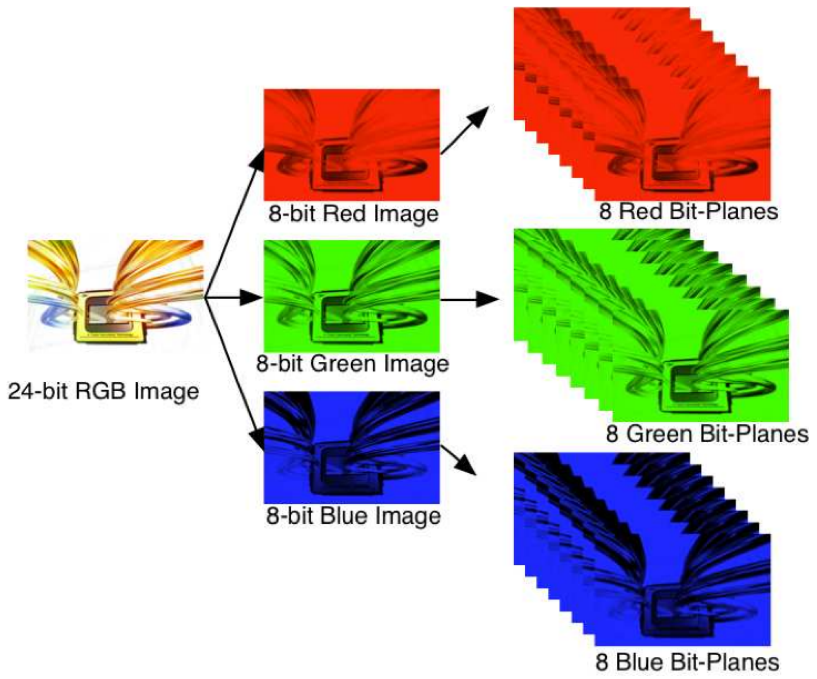
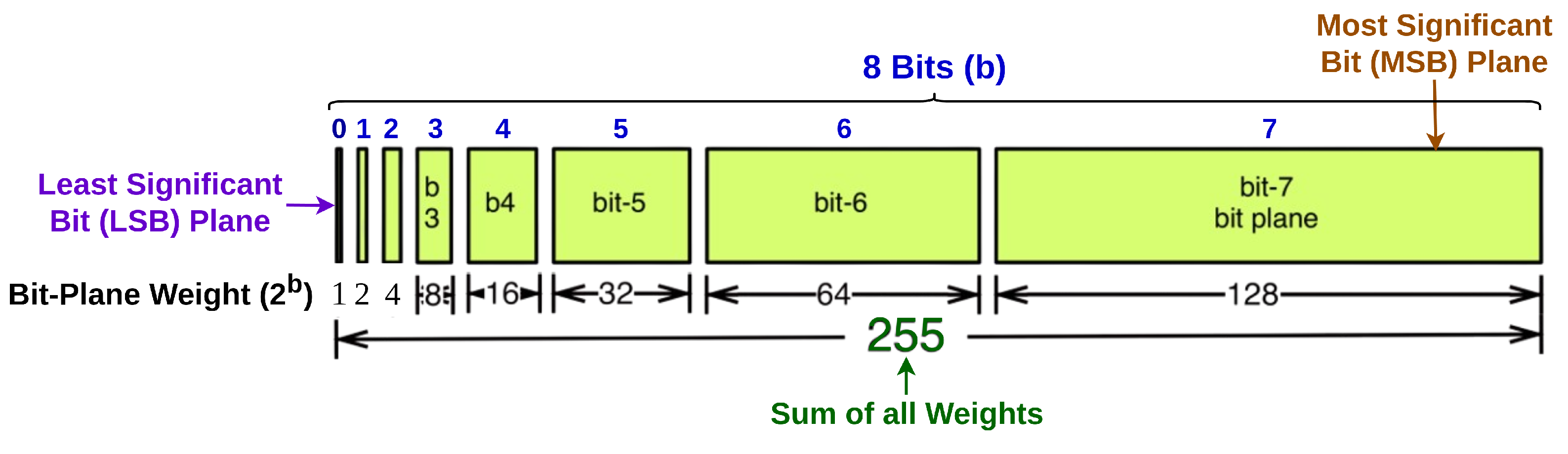
The second option leverages the opportunity to improve performance by reducing the bit depth of the generated patterns. Reduced bit depth introduces quantization noise that degrades the fidelity of sinusoidal patterns. As a result, the spatial frequency observed in the captured modulated images can deviate from the nominal value specified as the experimental parameter. DLP projector models use the Most Significant Bit (MSB) bit-planes to project maximum brightness and the Least Significant Bit (LSB) to project darker regions of the pattern through the micromirrors (more details will be discussed in
Section 4.1). Hence, reducing the bit depth can significantly affect the quality of the generated patterns.
The third option completely eliminates the possibility of using a DLP projector. Furthermore, it must ensure an accurate mechanical positioning and trigger changes of the static films, along with the correct fixed waiting period.
In the fourth option, setting a fixed-time waiting period for changing patterns before taking an HS camera capture can achieve projection–capture synchronization. This option assumes that the DLP projector is already synchronized at the frame level with the pattern generator. If not, the synchronizer must be manually tuned by finding an optimal waiting period in seconds or milliseconds. Since the SOTA HSPy-SI system lacks frame-level synchronization, it relies on this manual tuning approach. However, it is challenging and time-consuming due to the large search space.
In addition, none of the first four options supports event-based triggering (e.g., interrupt-driven capture). As a result, they all rely on manually setting a fixed delay to align camera capture with projection, making precise synchronization difficult. Furthermore, the first and second options depend on the chosen DLP projector model; therefore, they are not suitable for a projector-model-agnostic synchronizer. The third option removes the possibility of using a DLP projector.
Finally, the fifth option implicitly uses the configurable fixed-time waiting period to compensate for frame latency caused by the DLP projector but offers more simplicity and flexibility through an interrupt-based tunable parameter, W = Frame Count to Wait.
After taking into account the limitations of options one through four, the fifth option has been explored and is thus proposed the methodology for a heterogeneous embedded board-based synchronizer, the HyperSI system. This system follows the same conventional TPD method [
3,
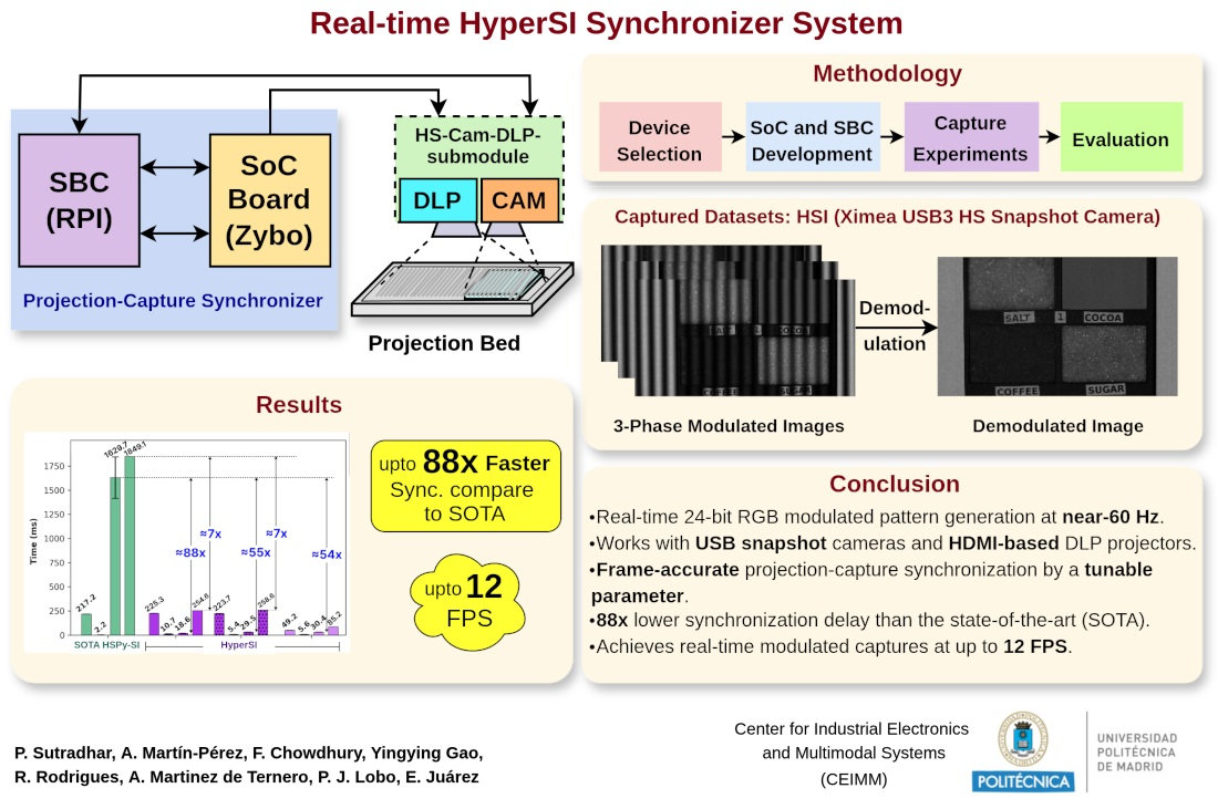
12] as the SOTA HSPy-SI system. An SBC and an SoC development board were used to develop the proposed HyperSI system. The SoC board was programmed to generate high-quality 24-bit RGB patterns for the three phases at any specific spatial frequency and send them to the DLP projector through the HDMI interface at ≈60 Hz. The DLP projector accepts and projects those patterns in video mode that require minimal user intervention (i.e., enabling video mode and disabling gamma correction). The SBC serves as the master controller; it triggers the HS snapshot camera and commands pattern changes over General-Purpose Input/Output (GPIO). Hence, the HyperSI system implements projection–capture synchronization through an SBC and SoC, whereas the SOTA HSPy-SI system uses a desktop computer for the same synchronization purpose. To improve the data acquisition rate and projection–capture synchronization, the HyperSI system introduces a tunable parameter,
W = Frame Count to Wait, to compensate for the delay caused by the DLP projector. DLP projectors use precise frame-based control to project patterns, which inherently introduces frame latency due to buffering, synchronization, and bit-plane processing. As a result, any new pattern must pass through a full frame cycle (e.g., VSync-triggered buffer swap) before being fully stabilized and displayed on the DMD. The SoC can be programmed to detect the generation of an individual frame accurately through the arrival of frame-generation interrupts. Thus, the arrival period of each interrupt refers to the Time per Frame (TF), which can be measured in milliseconds. Hence, a configurable camera delay has been implemented through the counting of interrupts of each frame generation for a particular pattern phase in the SoC. Therefore, a configurable delay is applied before camera capture that can be measured in milliseconds as
. After
W frame interrupts have been counted, the SBC executes the capture by the HS snapshot camera. Thus, the camera delay period equals the total count of
W frames; i.e.,
. Instead of tuning a fixed waiting period in milliseconds or seconds, the proposed methodology uses a configurable delay based on the frame count of the generated pattern. Since the DLP projector displays patterns in each frame and the SBC (via the SoC) generates and changes patterns in each frame, frame-accurate synchronization can be achieved. This approach drastically reduces the search space and avoids both over- and under-optimization of the system. So finally, it is necessary to find an optimal
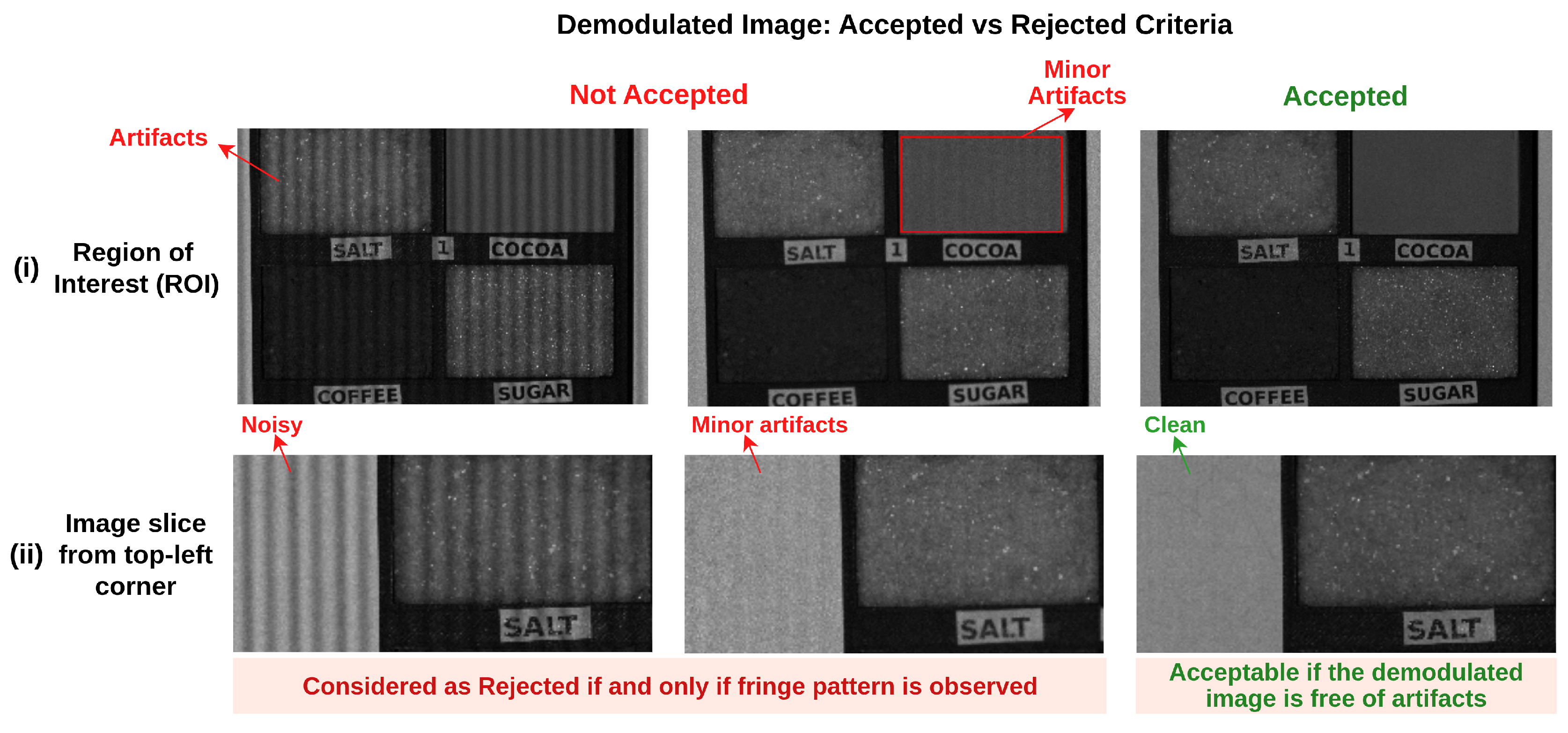
W number of frame counts until the DLP projector stabilizes the pattern on the projection surface; i.e., until no artifact is visible in the demodulated HS image captures. Thus,
W solves the projection–capture synchronization problem by implicitly compensating for the projector latency and also removes the dependence on any particular DLP projector model. Some of the aforementioned SOTA techniques perform sequential image acquisition band-by-band. The proposed methodology can also be adapted for these use cases by simply changing the camera (with USB 2 or 3) and/or projector (with HDMI). This is possible because projection–capture synchronization is not tightly coupled with any particular type of camera or projector model. The proposed system will be explored and compared with the existing SOTA HSPy-SI system. Then, this work will also evaluate the demodulation outputs and the system runtime performance of the proposed system.
The remainder of the paper is organized as follows.
Section 2 explains the background of this research work with respect to the SI technique.
Section 3 briefly describes the SOTA HSPy-SI system. A detailed description of the proposed HyperSI system is given in
Section 4.
Section 5 presents the results obtained from the experiment. Finally,
Section 6 briefly discusses the results of the experiment, and
Section 7 suggests ideas for future opportunities from this research work.
4. Materials and Methods
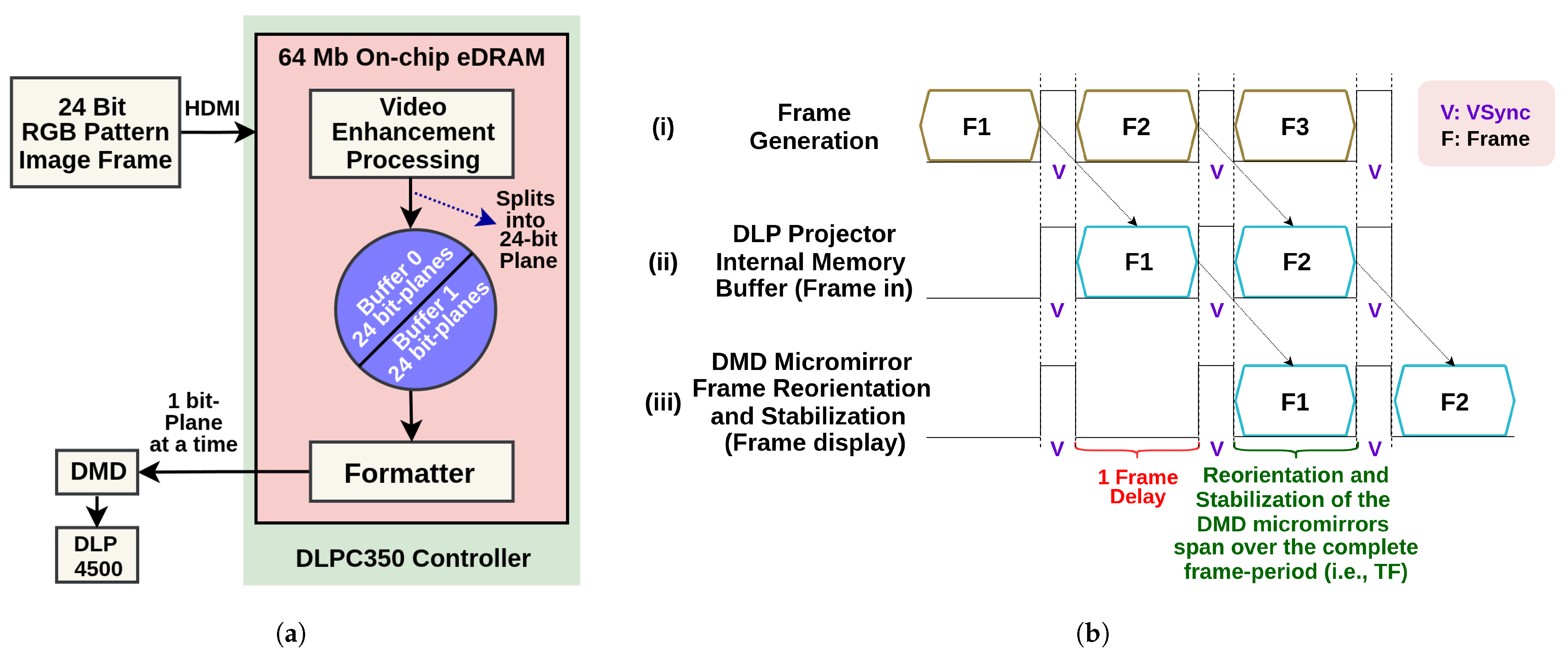
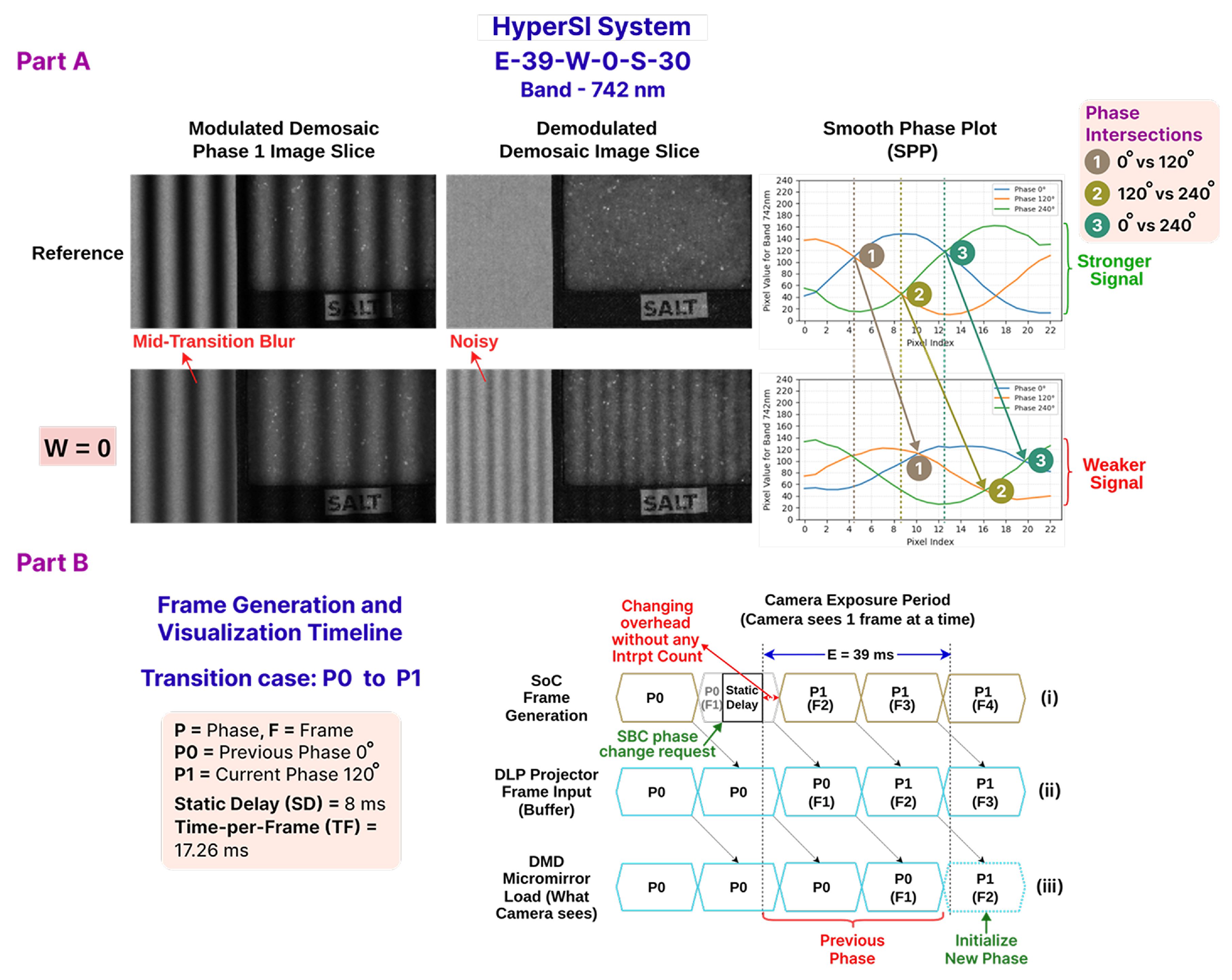
In an ideal scenario, when a pattern frame for a specific phase is changed and projected, the HS camera connected to the computer should immediately capture that updated pattern on the projection surface. However, in practice, this is not the case. The DLP projector introduces latency when rendering a pattern frame for two reasons: (i) the dual-buffer architecture and (ii) the time required for micromirror reorientation and stabilization (
Figure 3a,b). As a result, immediately after a phase change, the HS camera is unable to capture the correct pattern projected on the projection surface. To address this issue and achieve reliable projection–capture synchronization, this study proposes the HyperSI system as its primary contribution.
Section 4.1 briefly discusses how the projector introduces latency.
Section 4.2 explains how the novel
W = Frame Count to Wait parameter has been integrated with the projection–capture synchronization solution.
Section 4.3 lists the components used for the proposed system.
Section 4.4 illustrates the system design of the proposed methodology.
Section 4.5 outlines the methodology used to develop and evaluate the proposed system.
Section 4.6 and
Section 4.7 describe the development flow in the SoC and SBC environments, respectively. Finally,
Section 4.8 explains the implementation of projection–capture synchronization.
4.1. Latency Caused by the DLP Projector to Refresh a Pattern Frame
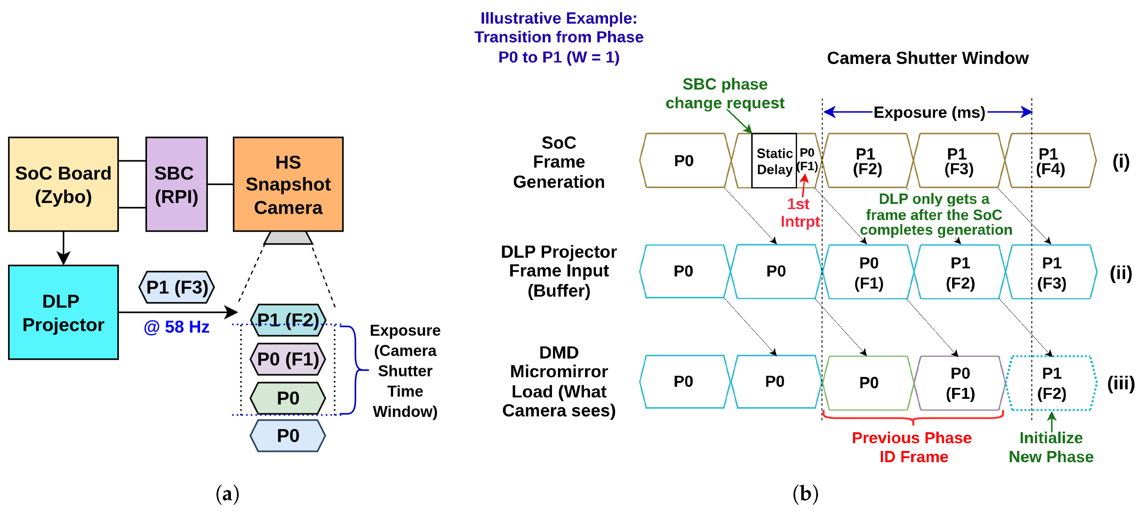
Figure 3a shows an abstract overview of how the DLPC350 proprietary controller manages the pattern stream from an input 24-bit RGB parallel interface to the DMD within the DLP
® LightCrafter
™ E4500 MKII
™ projector used in this experiment. Each complete pattern frame projected by the projector, whether retrieved from internal flash memory or generated by an external pattern source, is expressed in the projector datasheet as an n-bit frame. For example, a frame containing three 8-bit channels (RGB) is classified as a 24-bit frame [
45]. The DLP projector has two modes: video and pattern sequence. The video mode has been selected because it works with minimal user intervention for the default settings. A 24-bit RGB pattern is received through HDMI and passed to the Video Enhancement Processing (i.e., Video Processing) block. This block performs various processing tasks (such as Degamma, Primary Color Correction, Chroma Interpolation, Scalar, Overlap Color Processing) on the input digital image. Internally, the DLPC350 stores two 24-bit frames in its memory, resulting in a 48-bit frame display buffer that works like a ping-pong buffer. It allows the DLPC350 to send one 24-bit frame to the DMD micromirror array, while the second buffer is filled with the new frame streamed through the 24-bit parallel RGB (i.e., HDMI) or Flat Panel Display (FPD)-Link interface. After the display of the previous frame is completed, the
VSync pulse coming with each frame through HDMI triggers a buffer swap, and the newly filled frame from the other 24-bit frame buffer is delivered to the DMD, one bit-plane at a time (further explanation given in
Appendix B.1,
Figure A4). Subsequently, the DMD sends each of the received bit-planes to the micromirrors. The DLPC350 controller intertwines and interleaves bit-planes, per-color time slots, and color frames to improve image quality. Finally, the controller uses a frame period to initialize and stabilize a pattern, as illustrated in row (iii) of
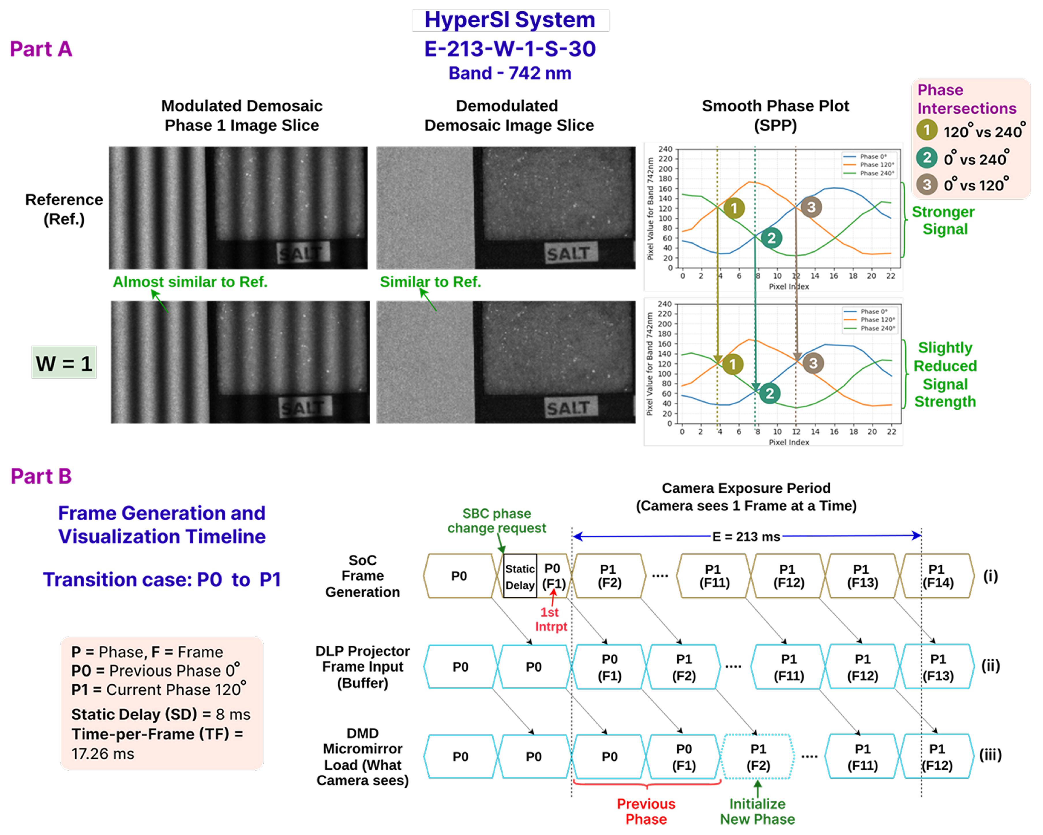
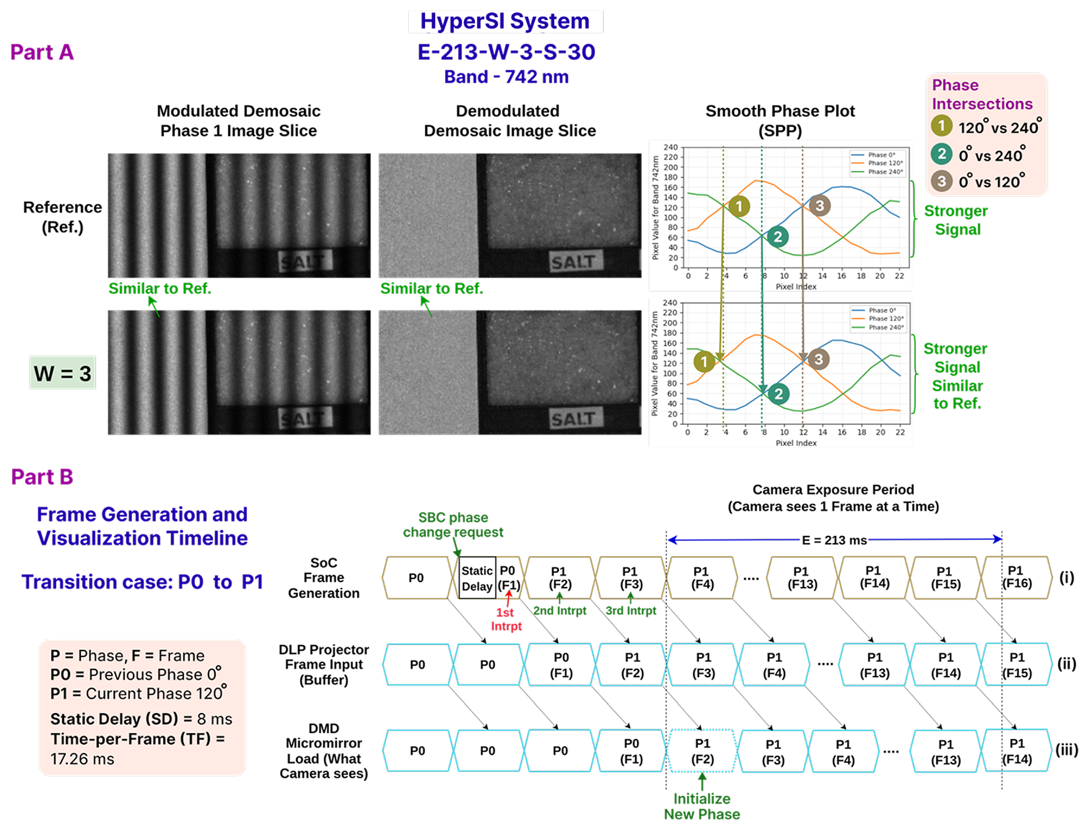
Figure 3b. This figure also simplifies the 48-bit frame buffer shown in
Figure 3a by representing it as a timeline DLP Projector Internal Memory Buffer (Frame in) in row (ii). Row (i) shows frame generation with
VSync pulses, with the first frame F1, then F2, and so on. Row (ii) shows the DLP internal buffer that receives a new frame F1 at each
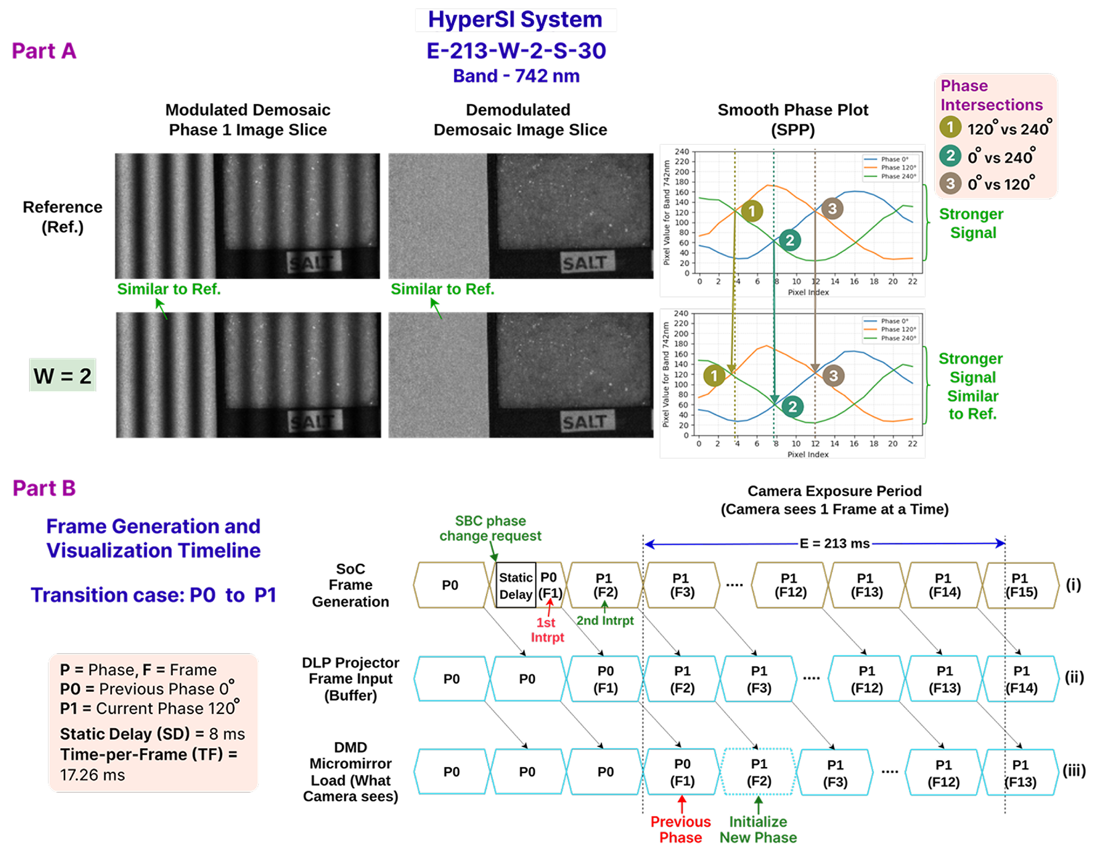
VSync rising edge (diagonal arrows indicate transfer). Row (iii) shows DMD micromirror reorientation and stabilization with a one-frame delay (marked in red); the first F1 frame then requires the full frame period (1 TF) to settle. Thus, a frame period is spent in the buffer; therefore, a one-frame display latency always exists between the received pattern input and the output image rendered by the DMD micromirror array. Another frame period is spent reorienting and stabilizing the micromirrors to project a stable frame.
The way in which the controller utilizes an entire frame period to initialize and stabilize a frame after it is released from the buffer is further detailed in
Appendix B.1.
4.2. Projection–Capture Synchronization with W Parameter
The SOTA HSPy-SI system uses a fixed waiting time to compensate for DLP projector latency when capturing a modulated HS image at the correct pattern phase. The DLP LightCrafter 4500 projector is driven by the DLPC350 controller, which internally implements a dual-frame ping-pong buffer architecture when operating in video-streaming mode [
33,
45]. In this architecture, one frame is projected on the Digital Micromirror Device (DMD) while the next incoming frame from the HDMI interface is simultaneously buffered. Consequently, the optically projected frame corresponds to the previously transmitted HDMI frame, introducing an inherent pipeline latency of approximately one frame period (i.e.,
) between frame transmission and optical projection (
Section 4.1). This deterministic one-frame delay requires that the camera capture be delayed appropriately so that the acquisition occurs when the intended SI pattern is fully stabilized on the projection surface.
However, finding the exact frame-based delay before camera capture is difficult in the SOTA HSPy-SI implementation because the system relies on millisecond-scale waiting times that cannot account for factors such as precise frame-generation timing, dispatch latency during phase switching, and runtime overhead introduced by the operating system (OS). As a result, selecting an appropriate delay requires extensive trial and error across a large search space. To address this limitation, the proposed system introduces a frame-based synchronization parameter W = Frame Count to Wait. Instead of specifying a delay in milliseconds, W defines the number of generated frames for which the system waits before triggering the camera capture. Since the frame-generation process occurs at a known Frame Refresh Rate (FRR), this approach effectively provides a deterministic compensation for the projector pipeline latency. Thus, the delay applied before camera capture becomes proportional to the number of frame interrupts detected by the frame generator.
Accurate control of individual pattern-frame generation at a typical 60 Hz FRR is difficult to achieve on consumer-grade hardware such as SBCs or desktop PCs. On these platforms, the video output is abstracted and managed by multiple layers of the OS, including user applications, shell environment, system libraries, runtime components, system call interfaces, kernel services, hardware abstraction layers, and finally the hardware itself. This layered architecture prevents deterministic control over individual frame generation. Although some MCU evaluation boards support video output at resolutions such as
[
46],
[
47],
[
48], and
to
[
49], most of these boards lack an integrated HDMI interface and do not support the resolution requirements of the selected DLP projector. For example, the RP2040-PiZero includes a DVI interface capable of driving HDMI displays, but its maximum resolution is limited to
[
50].
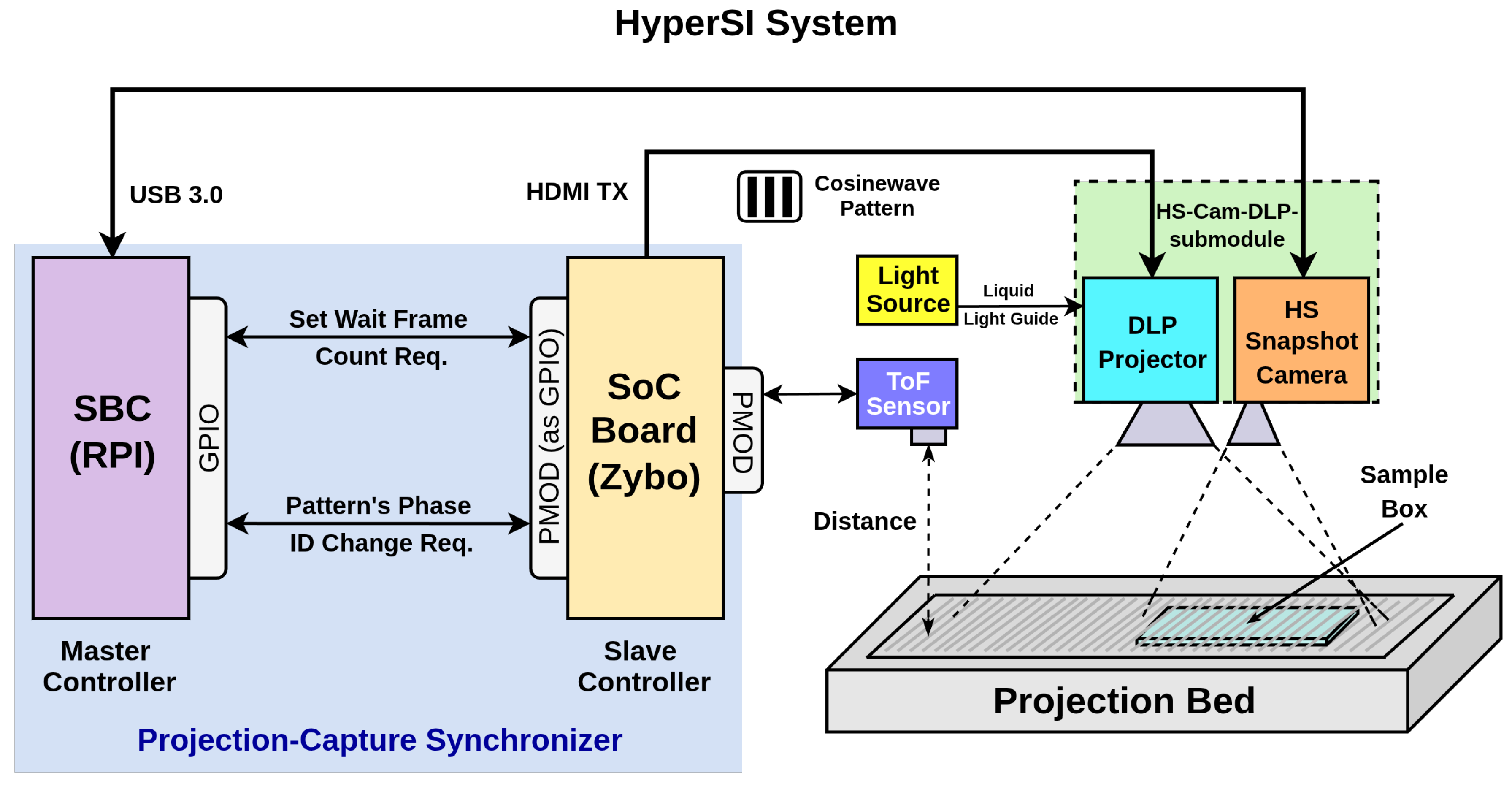
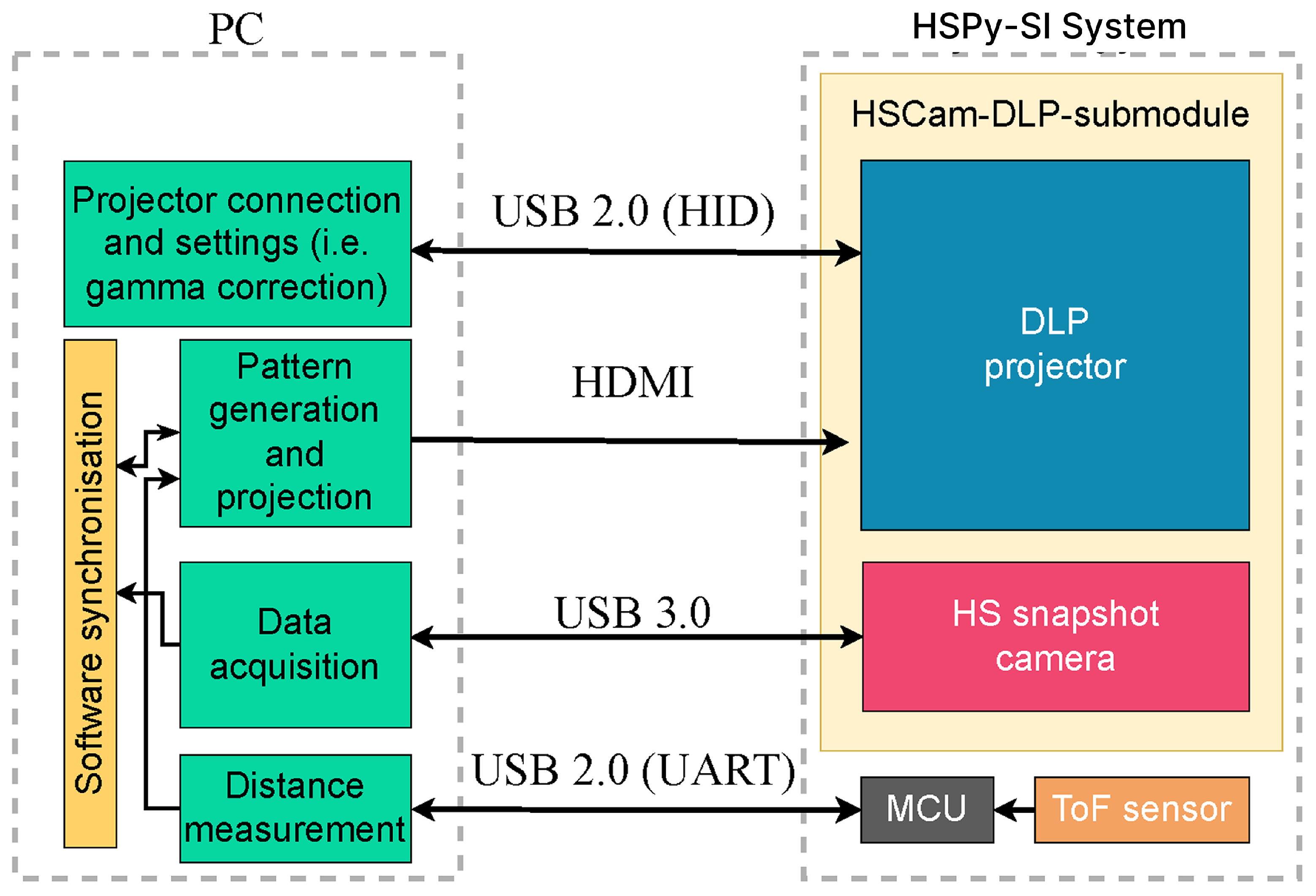
Based on these design considerations, a heterogeneous embedded architecture was selected, as shown in the proposed solution concept and the final system design in
Figure 4 and
Figure 5, respectively. An SoC development board with an HDMI transmitter (TX) peripheral is used for high-performance pattern generation and frame dispatch to the DLP projector. Typically, such SoC platforms contain programmable logic (PL) and an embedded processor. The PL is responsible for generating the SI patterns, while the processor controls the pattern-generation process. The SoC board must also provide PMOD interfaces to connect auxiliary sensors, such as a ToF sensor used to measure the distance between the projector and the projection target. The measured distance can then be provided to the pattern generator implemented in the PL.
To operate the HS snapshot camera, a USB3 interface is required. However, most SoC development boards lack a USB3 interface to reduce manufacturing costs, manage limited board space, and satisfy the low-bandwidth requirements of typical peripherals. Therefore, an external computing device with a USB3 interface is required to control the camera. An SBC with USB 3.0 connectivity is suitable for this purpose because of its compact form factor and suitability for space-constrained environments. Since the SBC controls camera acquisition, it also orchestrates pattern changes on the SoC board. Communication between the SBC and the SoC is therefore established through GPIO pins following a half-duplex communication protocol. In this architecture, the SBC acts as the master controller, responsible for camera triggering and pattern phase switching, while the SoC operates as the slave controller, responsible for deterministic frame generation.
Within this proposed design architecture, as illustrated in
Figure 4, the SoC uses the parameter
W to control the generation and counting of individual pattern frames through frame-synchronous interrupts. The parameter
W can be explained using an example scenario. The DLPC350 controller requires at least two consecutive input frames of the same pattern (e.g., phase 0) before the micromirrors stabilize and the corresponding pattern is fully projected onto the target surface (
Section 4.1). If the SoC generates pattern frames with a period of approximately
ms (corresponding to a 60 Hz FRR), setting
results in a capture delay of approximately
ms before the SBC triggers the HS image acquisition. In this way, the frame-based delay mechanism directly compensates for the one-frame projection latency introduced by the DLPC350 display pipeline while ensuring that the camera captures the stabilized pattern phase. Compared to millisecond-based delays, the
W-based synchronization approach significantly reduces the search space for delay tuning (i.e., compensation) and provides deterministic control over the number of stable projected frames observed by the camera. This parameter is critical for validating frame-level synchronization while performing the modulated captures and their effect on subsequent demodulation quality.
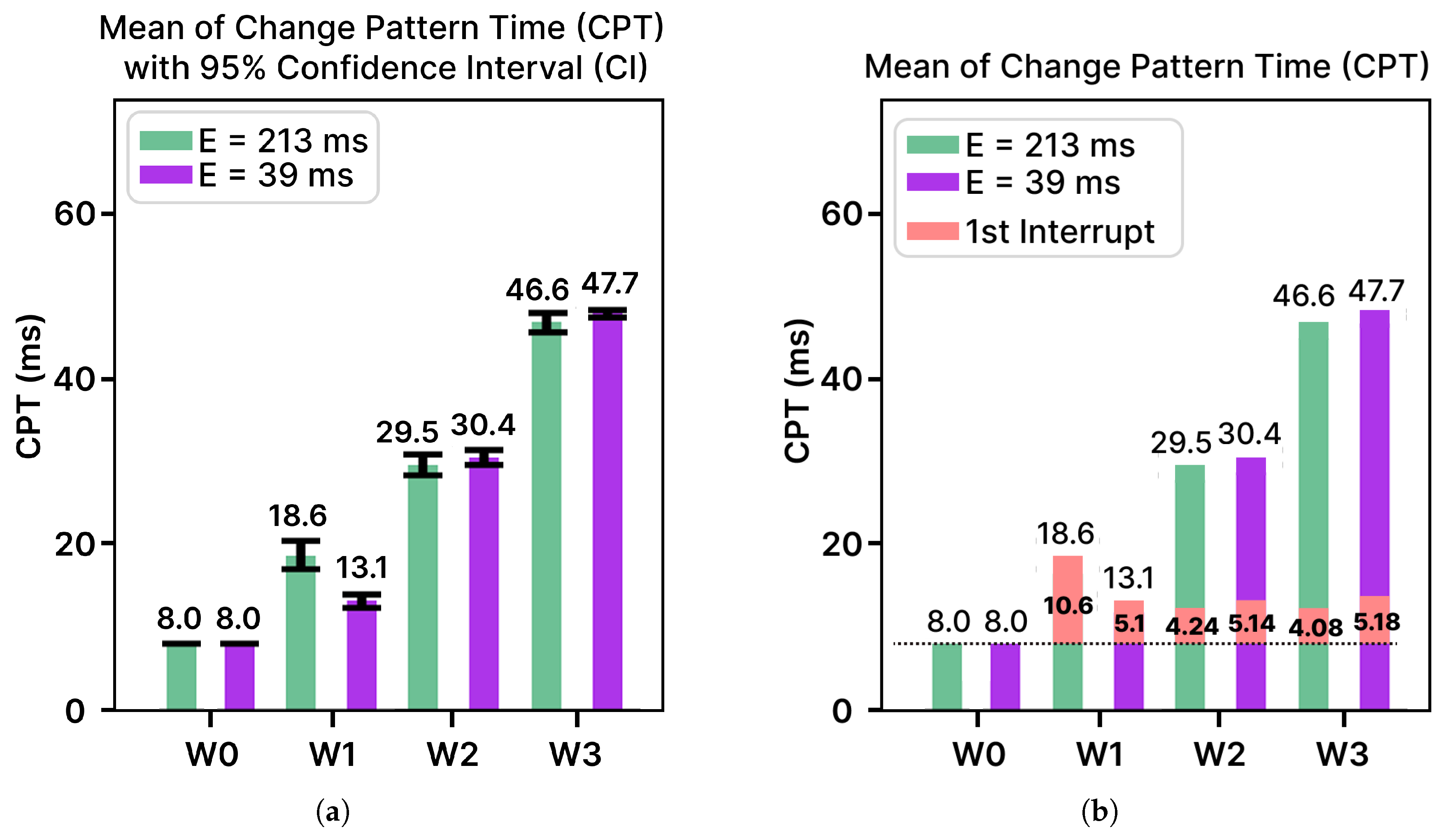
Section 5.5.3 describes the frame-level synchronization validation procedure used to verify the correct temporal alignment between pattern projection and camera capture. In that section, the Change Pattern Time (CPT) is formally defined using Equation (
10), where the capture delay is expressed as the sum of the static delay (
, i.e., delay introduced for GPIO communication overhead), and sequential frame interrupts are counted according to the configurable parameter
W. Since each interrupt interval
approximately equals the frame period
, the parameter
W directly determines the number of frame periods that must elapse before initiating capture. Furthermore, Equation (
11) derives the timing of the first interrupt
from the measured CPT values, enabling verification of the temporal relationship between frame generation and capture triggering.
The parameter
W therefore plays a central role in both defining and validating the synchronization delay. By controlling the number of frame interrupts counted before capture,
W effectively compensates for the deterministic projection latency introduced by the DLP projector pipeline described in
Section 4.1. Validating the CPT and the corresponding
values ensures that the capture is triggered only after the intended pattern frame has propagated through the projector pipeline and stabilized on the projection surface. This verification step is essential for guaranteeing correct phase alignment between the projected pattern and the captured image, which directly affects the quality of the modulated captures and the accuracy of the subsequent demodulation process.
4.3. HyperSI Components
The HyperSI system utilizes a Raspberry Pi (RPI) 4 Model B as the SBC and a Digilent Zybo Z7-20 development board as the SoC platform. The used RPI 4 Model B has an approximate form factor (i.e., dimension) of 90 mm × 53 mm × 22 mm (length × width × height), while the used Zybo Z7-20 SoC evaluation board has an approximate form factor of 122 mm × 88 mm × 15 mm. The
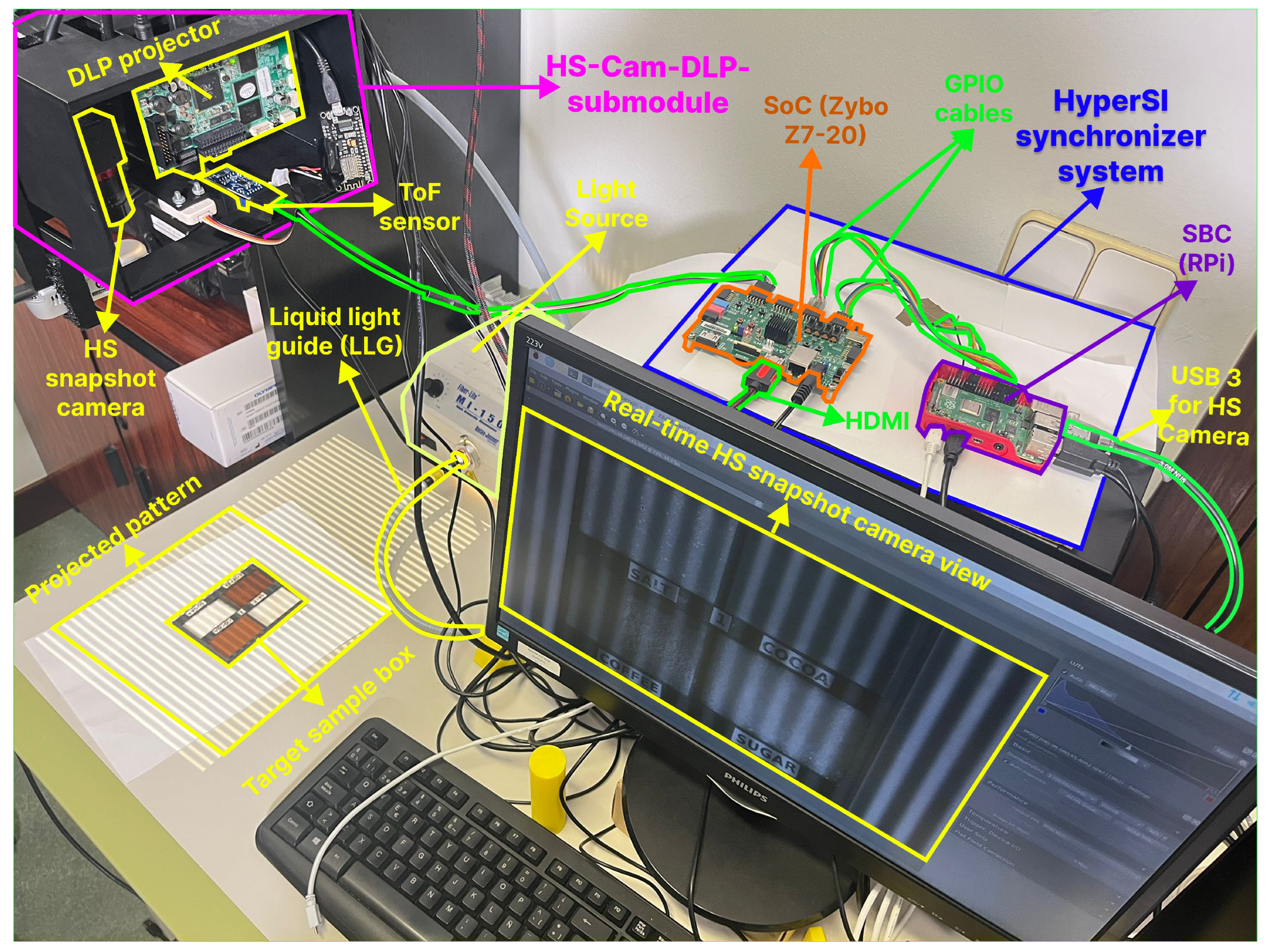
HS-Cam-DLP-submodule, illustrated in
Figure 5, houses the HS snapshot camera and the DLP projector. This submodule, originally used in the SOTA HSPy-SI system, is reused in the proposed design to maintain HW consistency. It integrates the HS snapshot camera, the DLP projector, polarizers, a light source, and a liquid light guide (LLG). More details are provided in
Appendix B.2.
4.4. HyperSI System Design
Figure 5 summarizes the concept of the complete system. Two heterogeneous embedded boards, an RPI as the SBC and a Zybo z7-20 development board as the SoC, are used to achieve projection–capture synchronization. The SoC board generates cosine-wave patterns for three different phases in real time with 1 Pixel-per-Clock (PPC) performance and controls the ToF sensor. The distance between the DLP projector and the projection surface can be measured using that ToF sensor and passed to the parameterized pattern-generator IP. The ToF sensor should be positioned as far as possible from the camera’s Field of View (FOV) so that the infrared light emitted by the sensor does not affect the reflected light coming out of the target sample box toward the camera. A light source feeds the infrared light to the DLP projector through an LLG so that the patterns are visible on the projection bed. An SBC-based system controls the HS camera to capture the HS image. It also controls the change (i.e., shifting) of the projection of the cosine-wave pattern among the
,
, and
phases in the SoC board. For simplicity, these respective phases are denoted by phase IDs =
consecutively, i.e.,
P0, P1, and
P2. This change is performed through the GPIO interface, which follows a half-duplex communication mode. After HS image capture of the projection surface for a particular phase of the pattern, the SBC tells the SoC to switch to the next pattern phase through GPIO signaling. Since the SBC controls the pattern projection on the SoC board, it acts as the master controller, while the SoC board serves as the slave controller.
4.5. Development Methodology
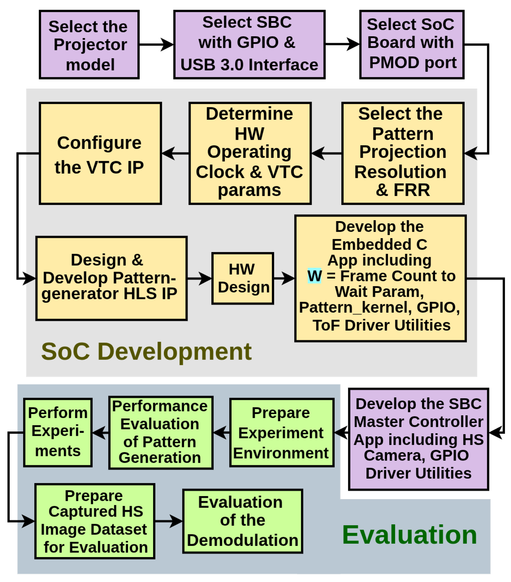
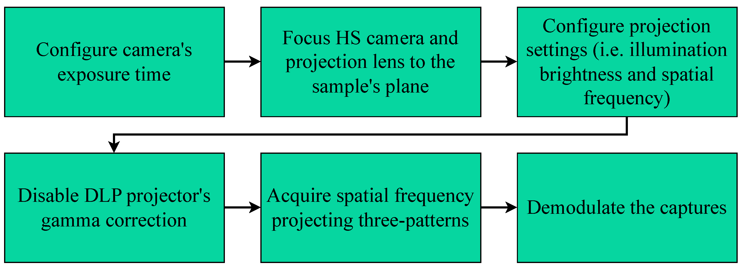
Figure 6 illustrates the complete development methodology, including the evaluation framework for the proposed system.
Select the projector model: A DLP projector evaluation model should be selected that supports video mode with continuous high-quality 24-bit RGB pattern streaming through the HDMI interface. Since the SOTA HSPy-SI system uses the DLPLCR4500EVM, which meets all the required specifications, the same projector has been selected for the proposed design. This choice also ensures consistency in capture experiments, allowing a fair comparison between the two systems.
Select an SBC with GPIO and a USB 3.0 Interface: A Raspberry Pi (RPI) 4 Model B is used as the SBC-based system. The board provides two USB ports, making it a suitable candidate for interfacing with and controlling an HS camera. A standard 40-pin GPIO header allows GPIO communication with other systems.
Select an SoC Board with a PMOD port: The Digilent Zybo Z7-20 development board model uses the AMD Xilinx Zynq-7020 SoC. The board has 6 PMOD ports that can be used for the GPIO interface with external systems (i.e., with an SBC).
Select the Pattern Projection Resolution and FRR: In the proposed design, the SoC is responsible for generating the pattern frames. Hence, its core hardware (HW) components (i.e., pattern-generator and Video Timing Controller (VTC) parameters) that are directly responsible for frame generation must be configured to match the required resolution and FRR (i.e., a non-standard resolution
@ 60 Hz FRR) of the chosen DLP projector (
Section 4.6.1).
Determine the HW operating clock frequency and VTC parameters: Since the HW has been designed from scratch, the core operating clock frequency (in MHz) must be determined to configure the entire HW system. Additionally, the VTC parameters need to be calculated to ensure the proper display of patterns across devices such as the DLP projector or a standard monitor. This process is particularly challenging because the frames must be generated for a non-standard resolution. To compute the core HW clock and VTC parameters, two key parameters must be determined: the pixel clock and the PPC requirement of the HDMI IP. The first step involves determining the pixel clock based on the selected resolution and FRR. To ensure consistent and reliable frame timing across Video Electronics Standards Association (VESA)-compliant devices, the pixel clock was calculated using the VESA standard. In addition, this standard also provided the required core VTC parameters. Next, the PPC count requirement was obtained (i.e., 1 PPC) from the HDMI IP provided by the board vendor. Finally, using the pixel clock and the PPC value, the clock frequency of the core HW was determined (
Section 4.6.2).
Configure the VTC IP: The VTC IP provided by the embedded development software (SW) vendor (i.e., AMD Xilinx; v2022.2) needs to be configured in generation mode because all the parameters were pre-defined for a given resolution and FRR. The VTC IP provides the video sink (i.e., AXI4-Stream to Video Out IP (AXI4S-VOut)) with all pre-calculated required timing parameters: active frame size, blanking intervals, sync pulse widths/polarities, and frame size. These parameters let the sink control the flow of pixels with TREADY, add the right HSync/VSync signals, and produce a stable video output for HDMI (
Section 4.6.3).
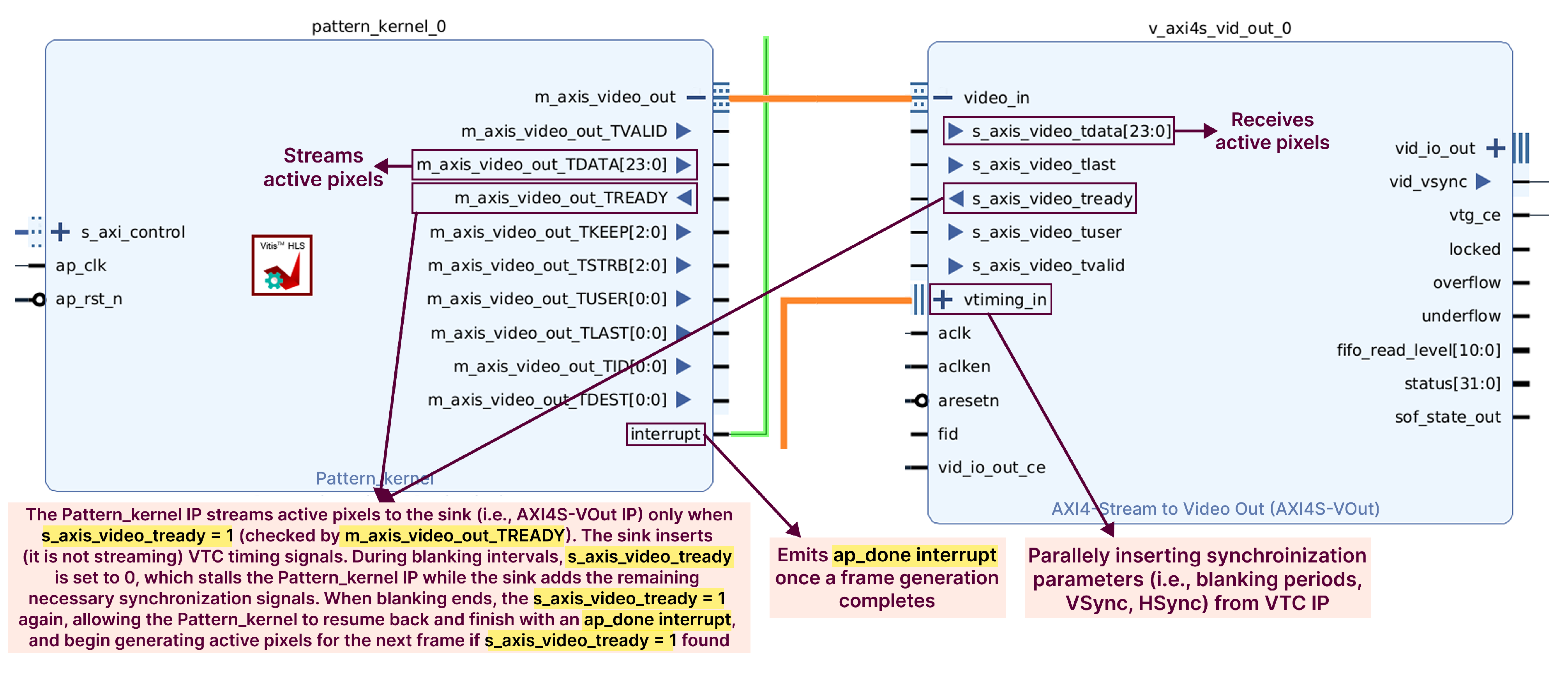
Design and develop the pattern-generator HLS IP: In high-performance frame generation, the video pipeline must remain tightly in sync with the timing of the AXI4S-VOut IP sink. Designing the pattern-generator IP for 1 PPC ensures deterministic behavior, where each handshake cycle corresponds to exactly one pixel. Furthermore, at least 1 PPC is necessary to guarantee that the generator can always keep up with the pixel clock expected by the video sink (i.e., AXI4S-VOut IP), maintain proper AXI4-Stream handshaking, and avoid underflows or sync errors. A methodology for developing a parameterized pattern generator (i.e.,
Pattern_kernel) capable of 1 PPC is presented using a dataflow model of computation (MoC) implemented through the HLS development approach (
Section 4.6.4). In particular, this approach supports pattern generation at any given resolution.
Develop the HW design: The HW design for the SoC has been developed by integrating all essential IP cores required for synchronized pattern generation and video output. This includes the Zynq-7000 PS IP, a custom-developed pattern-generator IP, the VTC IP, the AXI4S-VOut IP, and interrupt-enabled AXI GPIO IPs. Together, these components enable the frame-accurate control and synchronization necessary for real-time SI operation (
Section 4.6.5).
Develop the embedded SoC controller application: The embedded SoC controller application is responsible for generating parameterized patterns and implementing interrupt-based delays based on the
W parameter. It also manages the ToF sensor for distance measurement, which is used as input to the pattern generator. However, these operations are not autonomously controlled. Instead, the SoC application functions as a standalone slave, receiving commands via GPIO communication from the SBC master controller. This setup enables centralized control through the master application (
Section 4.6.6).
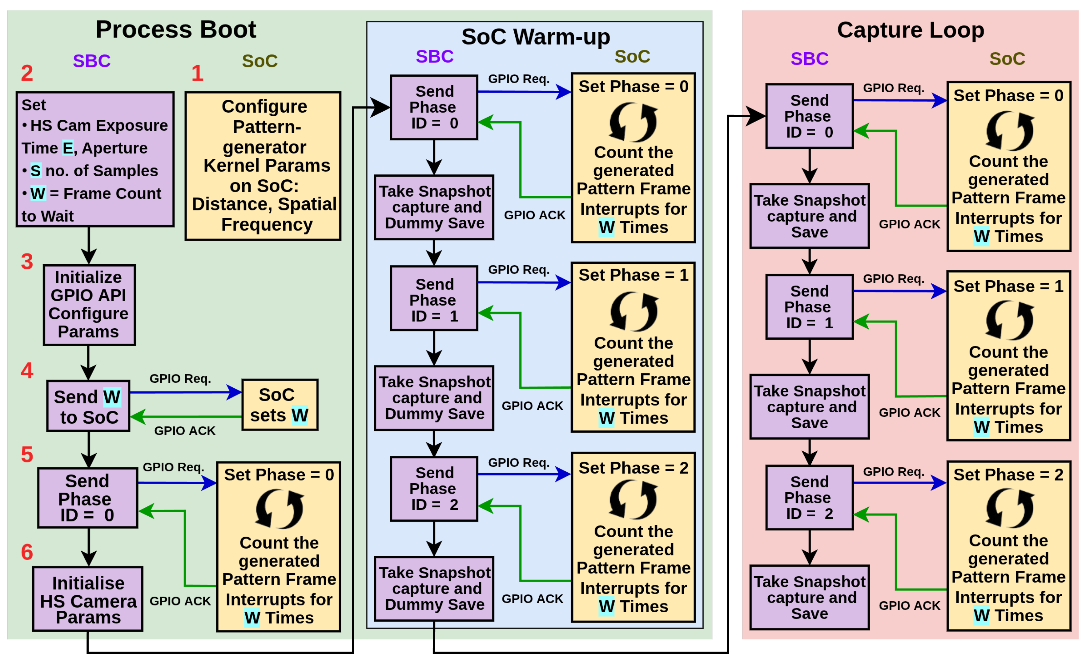
Develop the SBC master controller application: The primary responsibility of the SBC application is to perform HS image captures and coordinate phase changes on the SoC board through GPIO in a synchronized manner (
Section 4.7). Furthermore,
Section 4.8 outlined the projection–capture synchronization mechanism, which involves coordination between the embedded application running on the SoC board and the master controller application on the SBC.
Prepare the experimental environment: SI-based techniques such as SFDI require a controlled experimental environment, including stable ambient lighting and consistent projector conditions, to ensure reliable HS image acquisition (
Section 5.1). To maintain consistency in the evaluation, identical pattern-generation parameters were applied to both the SOTA HSPy-SI system and the HyperSI system (
Section 5.1.1). The HS snapshot camera was then configured (
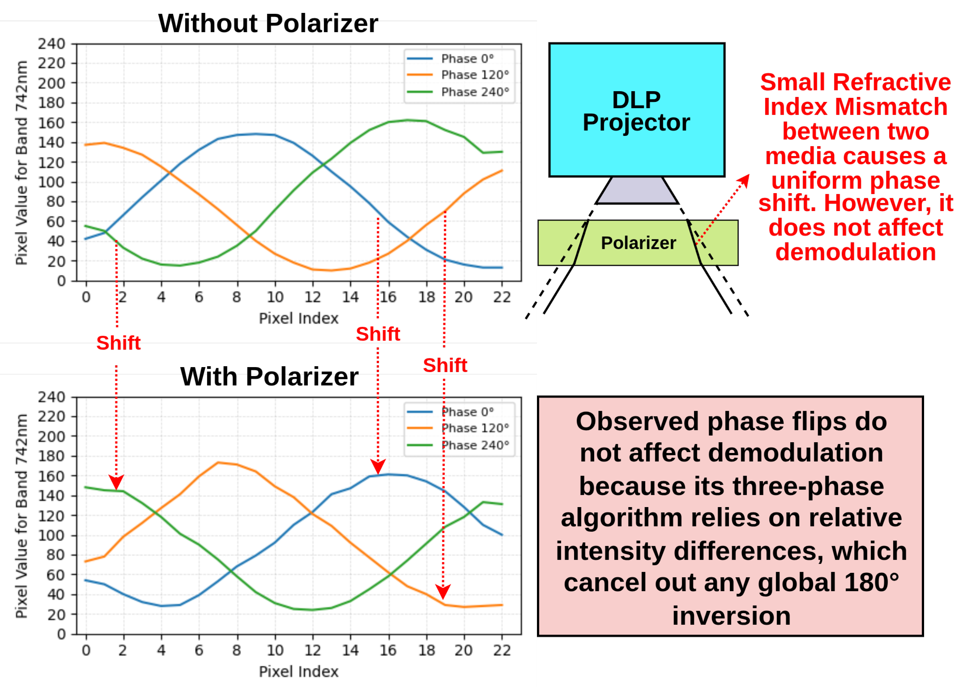
Section 5.1.2). As the SOTA HSPy-SI synchronizer was developed solely for use with polarizers, and the proposed HyperSI supports both polarizer and no-polarizer settings, optimal camera exposure times must be determined for each setting to prevent overexposure.
Evaluate pattern-generation performance: The pattern-generation performance of the proposed HyperSI system was evaluated with respect to the accuracy at the pixel level and the speed of frame generation (
Section 5.2). For a fair comparison, identical pattern-generation parameters were applied to the SOTA HSPy-SI system and the HyperSI system. The generated patterns from both systems were compared to verify whether the HyperSI implementation preserves the integrity of the pixel value (
Section 5.2.1). In addition, the FRR was measured to assess the execution speed achieved by the implementation of the HW-accelerated real-time pattern-generator kernel relative to the SW-based SOTA system (
Section 5.2.2). These analyses determine whether the HyperSI system fulfills the objective of producing high-quality 24-bit RGB modulated patterns at ≈60 Hz performance.
Perform experiments: Two settings were defined based on the exposure times determined for the camera polarizer and no-polarizer configurations. However, the proposed system includes an additional configuration parameter,
W. Taking all of these factors into account, the complete scheme of experimental capture configurations was established (
Section 5.3). Before the final target samples were captured, three acquisition steps were required. First, modulated white reference images were captured and demodulated to support preprocessing of both reference and final target sample images. Second, the target sample was prepared for acquisition (
Section 5.3.1). Lastly, the reference and final modulated target samples were captured (
Section 5.3.2), with the reference captures serving as a baseline to evaluate the final results.
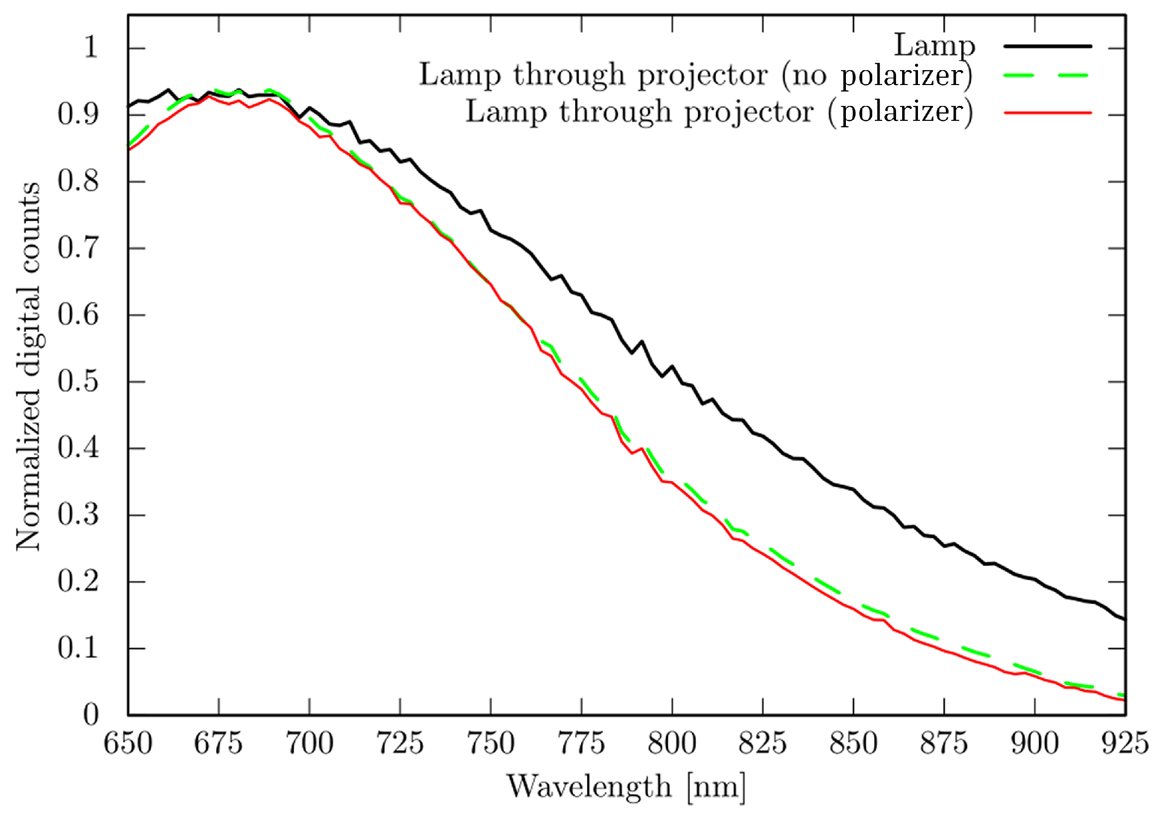
Prepare captured HS image dataset for evaluation: Since each HS camera capture contains 24 spectral bands, analyzing and evaluating all of them would be overwhelming. Therefore, a smaller subset of bands was first selected (i.e., 7 bands) based on spectrometer energy reflectance experiments (
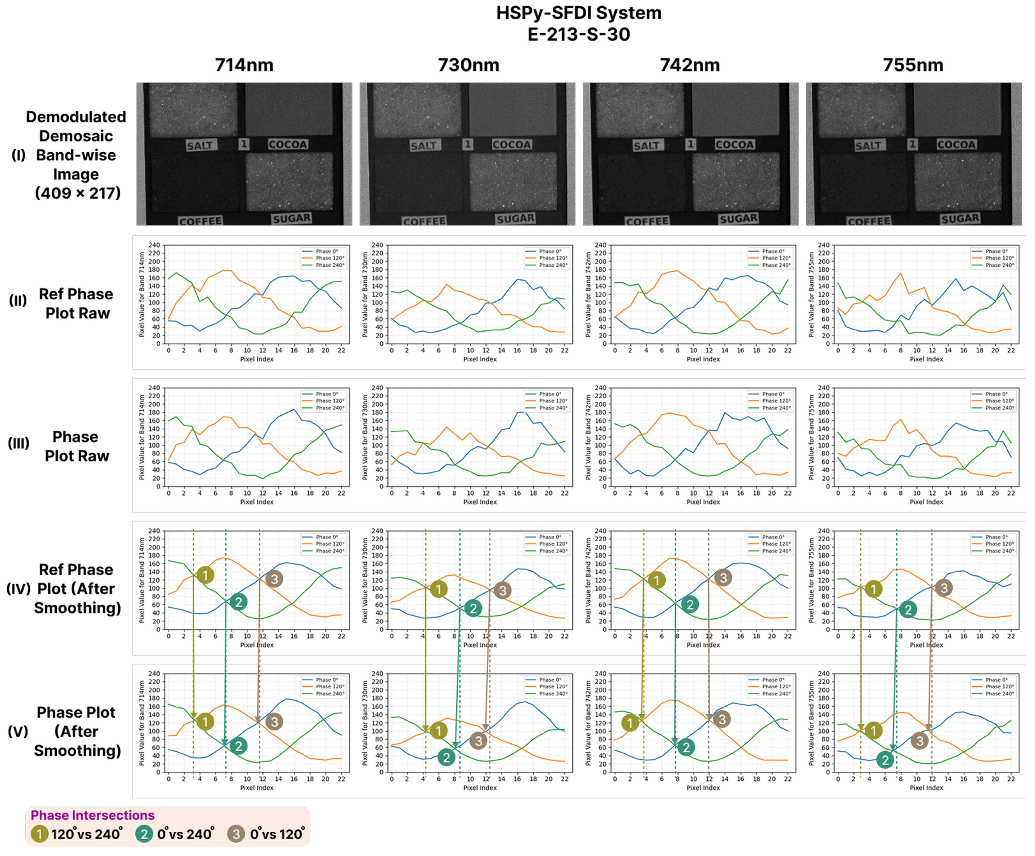
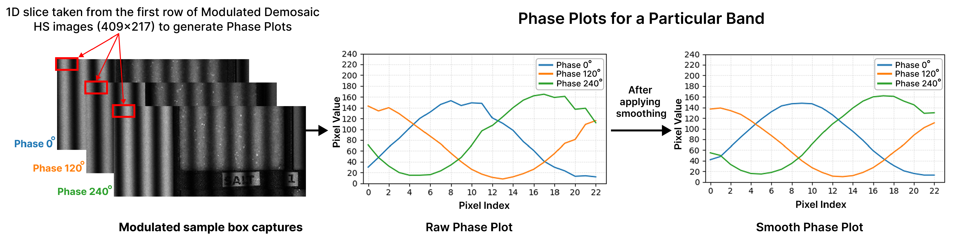
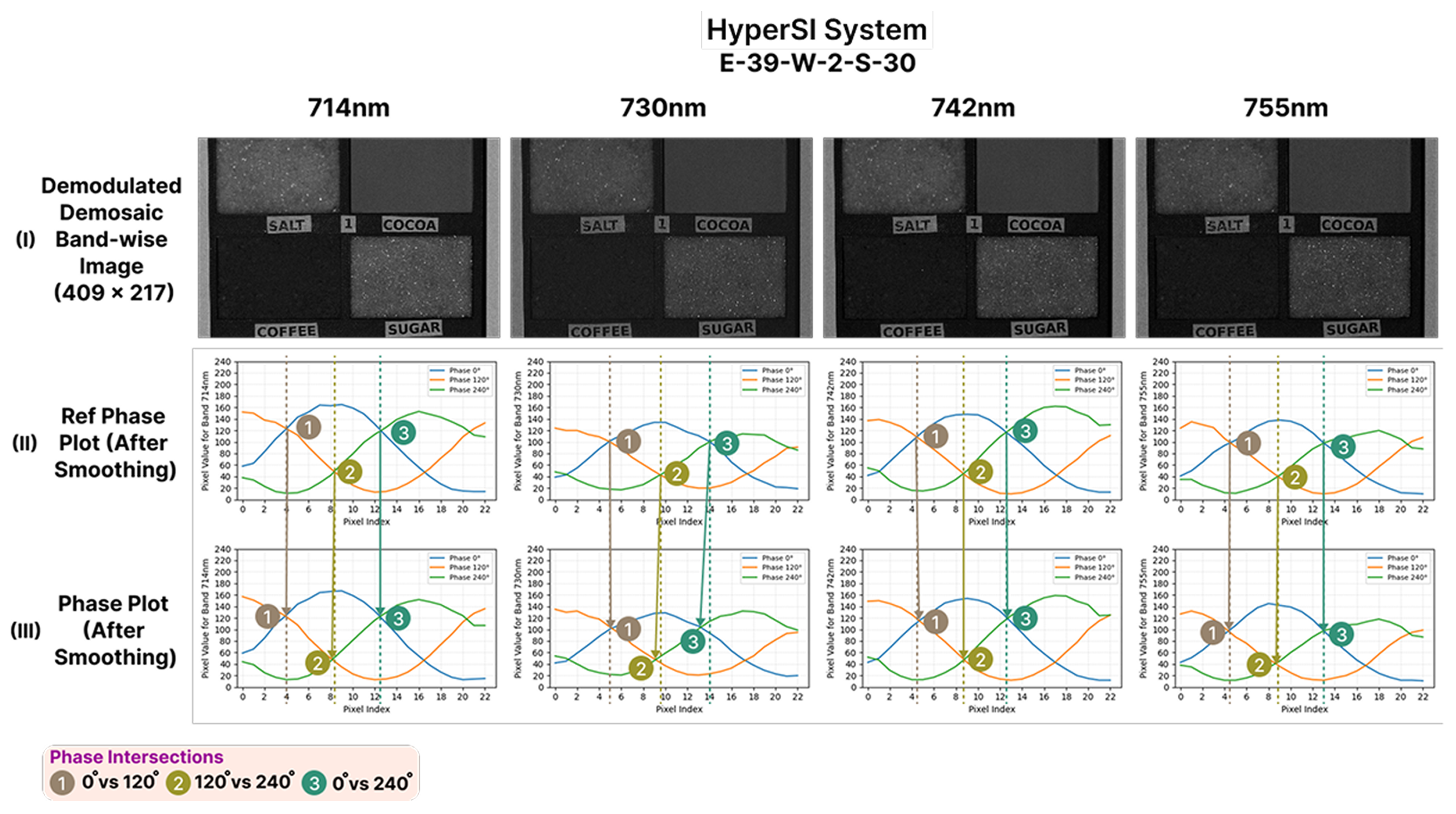
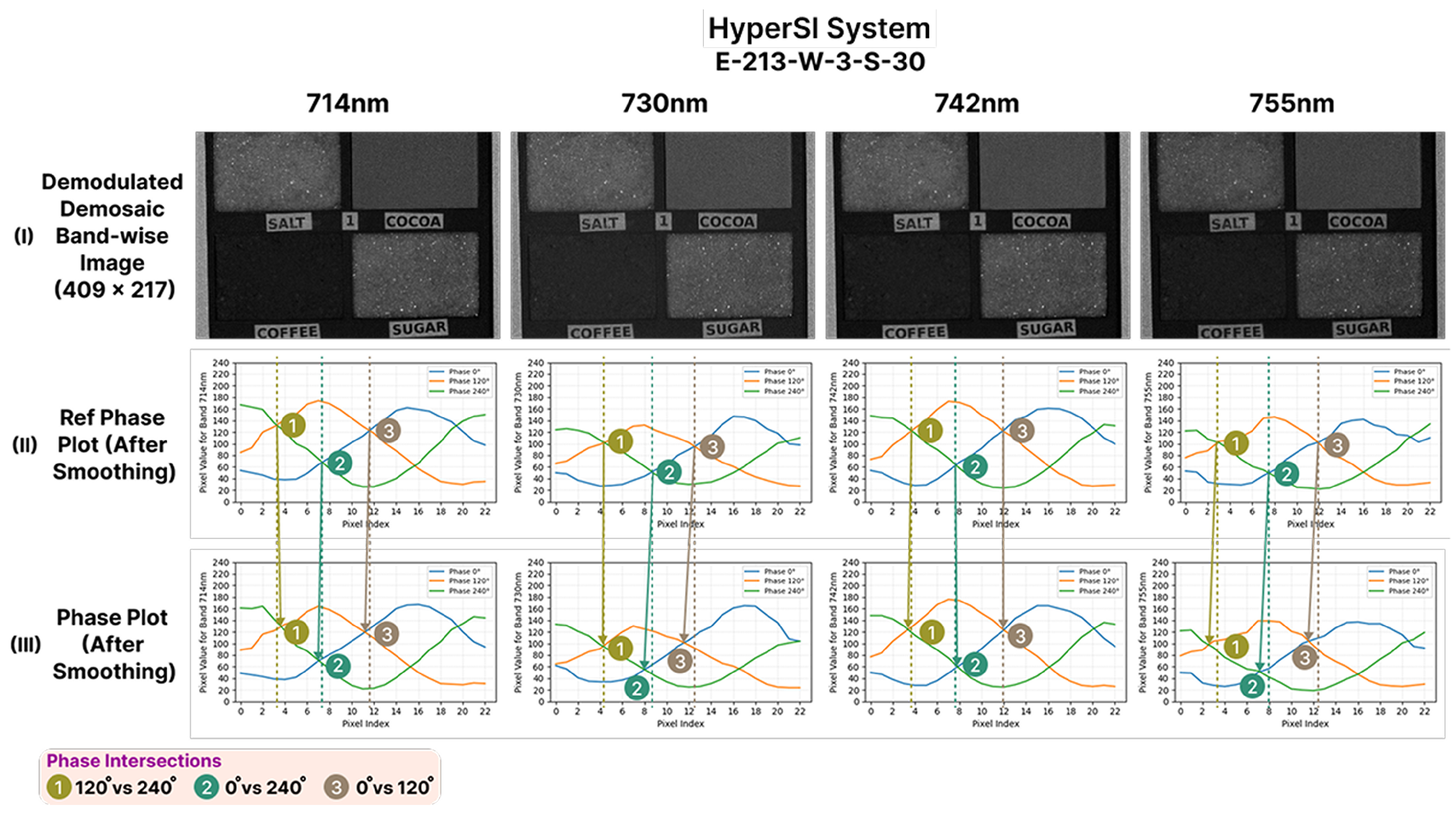
Section 5.4.1). This subset was then preprocessed, demosaiced, and used to generate raw and smoothed phase plots. From these, four bands with better signal quality and contrast were finally selected for further evaluation (
Section 5.4.2).
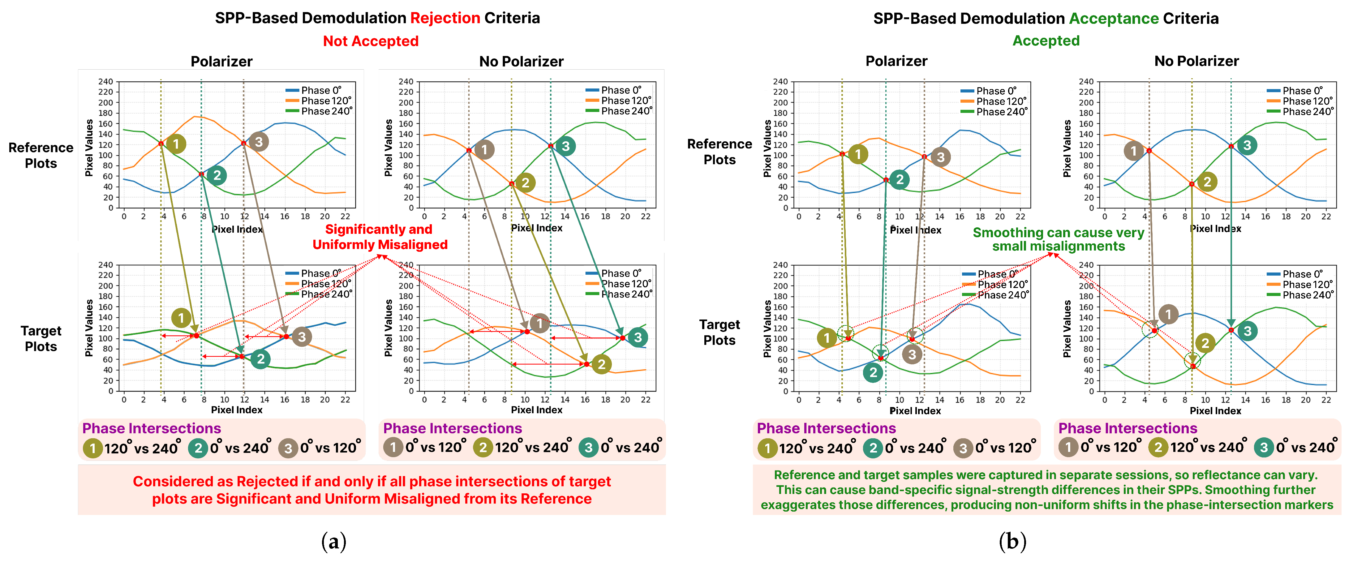
Evaluate demodulation: Evaluation criteria must be defined to assess demodulated images produced by the HSPy-SI and HyperSI systems (
Section 5.5.1). The evaluation of the SOTA HSPy-SI captures was straightforward, as it has no configurable delay and supports only the polarizer setting (
Section 5.5.2). In contrast to the SOTA system, the captures performed by the proposed system are directly influenced by the interrupt-based tunable parameter
W, which controls the number of frame-based interrupts used to delay camera capture. To achieve frame-level synchronization, the interrupt arrival period must match the frame period, i.e.,
. Therefore, a detailed experimental analysis was performed to measure the actual interrupt arrival periods and examine their timing behavior with respect to the
W parameter (
Section 5.5.3). The results confirmed that
I consistently matched with
and also validated the design choice (
Section 4.8) of the first interrupt originating from the frame of the previous phase. These findings are critical for ensuring the accuracy of
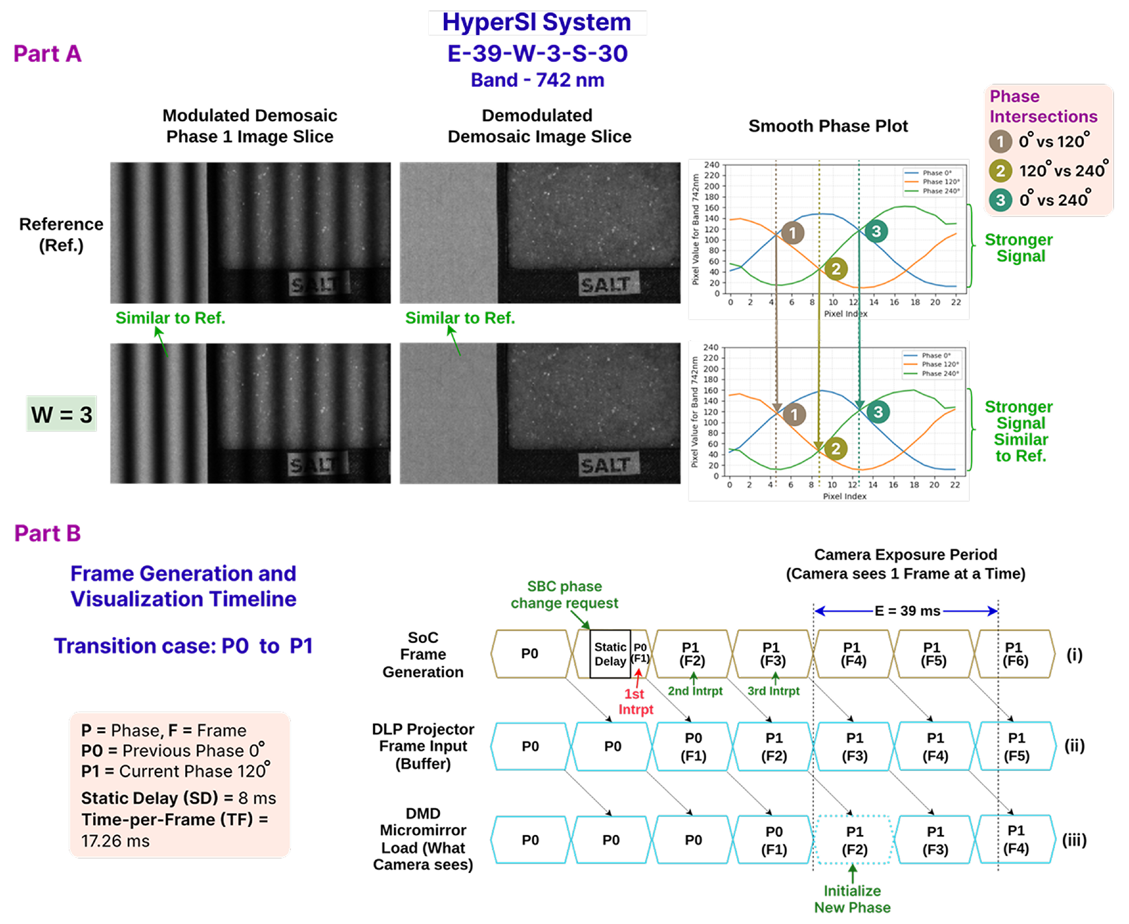
W, which determines the synchronization delay used to compensate for projector latency. The frame-sequence timeline has been introduced to establish a phase-synchronization and projection analysis framework that ensures that the demodulation evaluation accounts for every key event occurring during the experimental capture. By integrating the timing of SoC interrupts, the DLP dual-buffer behavior, the DMD micromirror stabilization process, and camera frame perception, the timeline provides a unified representation of how all components interact across phases for any
W configuration (
Section 5.5.4). Real-time-modulated captures, along with their corresponding demodulated outputs for a range of positive
W values (0–3), were evaluated using the same frame-sequence timeline concept (
Section 5.5.5,
Section 5.5.6,
Section 5.5.7,
Section 5.5.8,
Section 5.5.9,
Section 5.5.10,
Section 5.5.11 and
Section 5.5.12). The equations for the minimum required
W have been derived to guarantee proper phase alignment and stable projection timing between the SoC and the DLP projector (
Section 5.5.13). Finally, the runtime performance for both systems was analyzed (
Section 5.5.14).
4.6. Develop the HW/SW System in the SoC Environment
The core responsibilities of the HW/SW system are to generate and stream the pattern through HDMI for configurable parameters (i.e., distance, phase, spatial_frequency, throw_ratio, brightness), to control the ToF sensor for distance measurement, and to feed the distance value to the IP for pattern generation. The RPI SBC controls the pattern generation for particular phase IDs, i.e., 0, 1, and 2, representing , , and phases in the SoC-based system, through the GPIO half-duplex communication mode. This is why the Zybo SoC board acts as a slave controller with respect to the RPI SBC.
The use of proprietary AMD Xilinx SW for developing the HW/SW pattern projection application is further described in the Additional Materials in the introductory part of
Appendix B.4. The development of the embedded SoC board application follows the SoC Development block of the development methodology given in
Figure 6. These steps will be described in detail in the following sections.
4.6.1. Select the Pattern Projection Resolution and FRR
A
pattern projection at a 60 Hz FRR has been determined. The details can be found in
Appendix B.4.1.
4.6.2. Determine HW Operating Clock Frequency and VTC Parameters
The HW operating clock frequency of 86 MHz and the VTC parameters listed in
Table A2 have been calculated for the given pattern resolution of
@ 60 Hz. This clock rate will be used as the primary clock for the complete HW design. The details of the calculation method can be found in
Appendix B.4.2.
4.6.3. Configure the VTC IP
The VTC IP provided by the embedded development SW vendor (i.e., AMD Xilinx) needs to be configured in generation mode because all the parameters were pre-defined for a given resolution and FRR. The details can be found in
Appendix B.4.3.
4.6.4. Design and Develop Pattern-Generator HLS IP
AMD Xilinx Vivado SW includes a built-in pattern-generation IP, but it proved to be unsuitable for this specific application for two main reasons. First, it does not incorporate all the necessary elements to produce the required cosine-wave pattern. Second, it is entirely write-protected, preventing any modifications or enhancements. To overcome these limitations and deliver the desired functionality, an HLS-based methodology has been used to create a custom IP.
Since the HDMI IP used requires a 1 PPC rate for the pixel feed, the pattern-generator HLS IP (i.e., Pattern_kernel()) has been structured to allow dataflow modeling through function, loop, and stream pipelining techniques to achieve 1 PPC performance. This IP generates the pattern with a resolution of , where the width and height are, respectively, 912 and 1140, as required by the DLP projector. Since the entire HW design has to operate at an 86 MHz clock frequency, the top-level function Pattern_kernel() (i.e., IP kernel) is synthesized as a real-time video-streaming HW IP with an 86 MHz clock.
The AXI4-Lite slave interface exposes the scalar arguments tof_distance, phase, spatial_frequency, throw_ratio, and brightness and the implicit return of the Pattern_kernel IP as memory-mapped registers accessible from the PS (i.e., ARM CPU host). These arguments are therefore designed as runtime parameterizable controls rather than fixed constants, enabling the embedded application in the PS to configure the IP dynamically for different experimental requirements. As a result, the pattern generator functions as a fully controllable parameterized IP core, allowing parameters such as spatial_frequency, tof_distance, and phase, throw_ratio (i.e., to adjust other kinds of HDMI video-mode-supported DLP projector throw ratios) to be adjusted for future experiments without redesigning the HW IP.
In the present study, experimental validation was conducted at a single spatial frequency of
. The proposed pattern-generator HW IP was intentionally designed as a parameterized and deterministic real-time video-streaming block, in which the exposed runtime arguments, including
spatial_frequency, do not alter the underlying throughput of the synthesized design. The current HW IP has been developed and tested using fixed-point arithmetic with sufficient design precision and was parameterized to support spatial frequency values over the range from 0.001 to 0.999
for future experimental studies. Since IP synthesis maintained 1 PPC operation at the supplied 86 MHz clock for a fixed projector resolution of
, the generated video stream remains timing-deterministic for a given HW design, independent of the selected spatial frequency parameter within the supported configuration range. In addition, while running in video mode, the DLP projector locks the frequency of the incoming HDMI frame source and maintains its dual-buffer pipeline latency behavior for the received stream, regardless of the frequency of the incoming stream, and it can support up to 120 Hz, according to the manual, while maintaining this dual-buffer latency in a deterministic way. Since in video mode, this projector-side buffering mechanism is determined by the input frame timing rather than by the spatial frequency content of the projected pattern, the projection latency is expected to remain deterministic for different spatial frequency settings as long as the same video timing configuration is preserved.
Section 4.1 has already discussed the fundamentals of the dual-buffer latency mechanism.
For a standard 60 Hz video input, one frame occupies approximately 16.67 ms. In video mode, the DLP projector processes the incoming HDMI stream using a deterministic dual-buffer pipeline, in which one frame is loaded into the buffer while another frame is projected through the DMD micromirrors during the same frame period. This timing behavior is deterministic because the projector locks on the input frequency of the HDMI pattern-generator source.
Appendix B.1 further explains this behavior for the standard 60 Hz operating condition. In particular,
Table A1 shows how the 16.67 ms frame period (i.e., for 60 Hz) is deterministically divided into green, red, and blue bit-plane time slots. Furthermore,
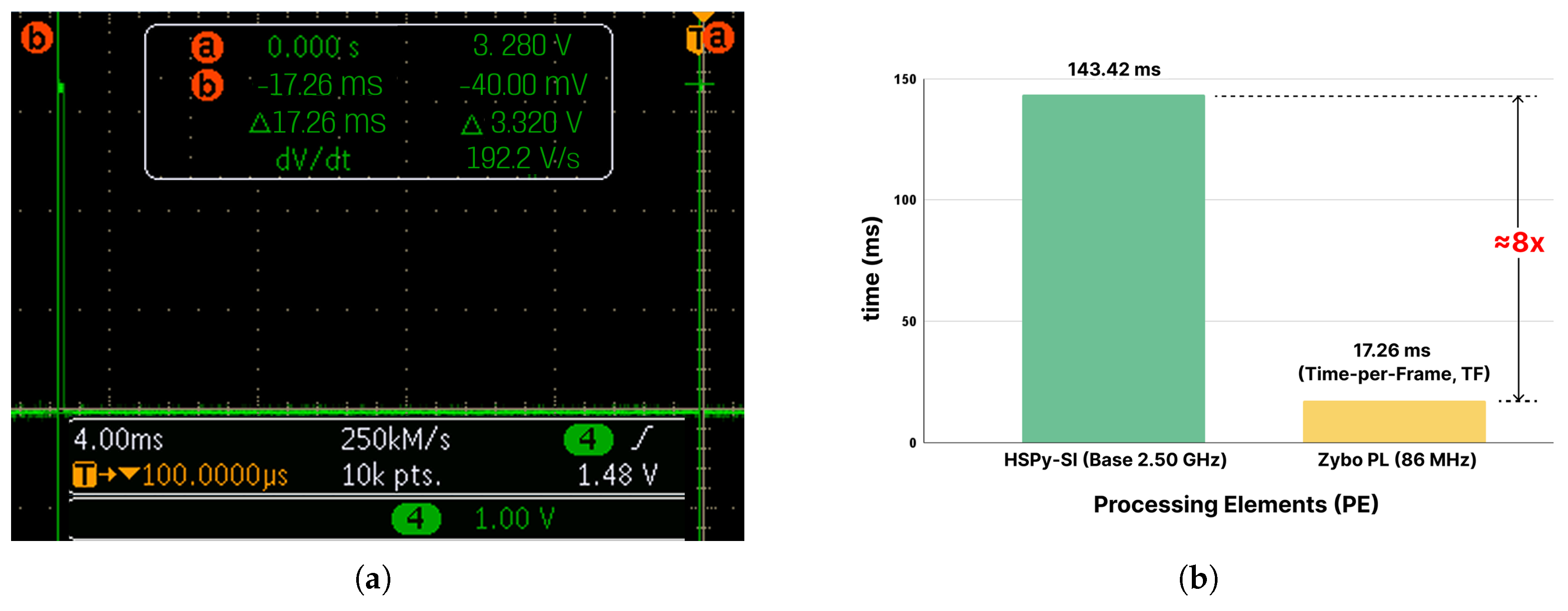
Appendix C.3.2 provides further experimental evidence of the same timing behavior for the current pattern-generator IP operating at approximately 58 Hz, where each frame takes 17.26 ms. Under this condition, the projector again maintains the same deterministic dual-buffer operation, where one frame remains in the buffer while another is projected through the DMD micromirrors, and the corresponding bit-plane timing slot distributions are listed in
Table A4.
The pseudocode of the dataflow computation model that generates pixel streams in the PL fabric is provided in the Additional Materials, Algorithm A1, and is described in further detail in
Appendix B.4.4.
4.6.5. HW Design
The entire hardware design is configured with an 86 MHz clock, which allows it to operate within a single clock domain.
Table 1 reports the utilization of post-implementation resources on the xc7z020 SoC. The proposed pattern-generator IP (i.e.,
Pattern_kernel) dominates the most of the utilization of HW resources; using 8634 LUT (16.23%), 7479 FF (7.03%), and 73 DSP48E1 blocks (33.18%). The video subsystem, composed of the
VTC,
AXI4S-VOut, and
RGB-to-DVI converter, contributes only a marginal logic overhead. The remaining control and interconnect infrastructure is grouped into
Others. In total, the complete design occupies 10,951 LUTs (20.58%), 10262 FFs (9.64%), 73 DSP48E1 blocks (33.18%) and 1 BRAM (0.71%).
The details of the HW design illustration and description can be found in
Appendix B.4.5.
4.6.6. Embedded SoC Application (SW)
The embedded SoC application functions as the slave controller, managing both the display and the phase transitions of the projected patterns. The ToF sensor collects measurement data and transmits the readings to the pattern generator running on the SoC. The SoC communicates with the SBC master controller via GPIO and implements a configurable, interrupt-based, frame-level delay mechanism. The details can be found in
Appendix B.4.6.
4.7. SW System in the SBC Environment
The SW system in the SBC environment acts as the master controller by controlling the pattern projection on the SoC board through GPIO, taking HS image captures, and finally saving them to the disk. The complete process by which the SBC controls the SoC to achieve projection–capture synchronization is further described in
Appendix B.3.
Figure A7 in the same section illustrates the operational workflow of the SBC (i.e., the SBC column). This flow is further detailed as a pseudocode in Algorithm A2, along with two stages: boot (
Appendix B.5.1) and capture loop (
Appendix B.5.2).
4.8. Implement Projection–Capture Synchronization
Section 4.2 introduced the projection–capture synchronization concept; this section details its implementation on the SoC board.
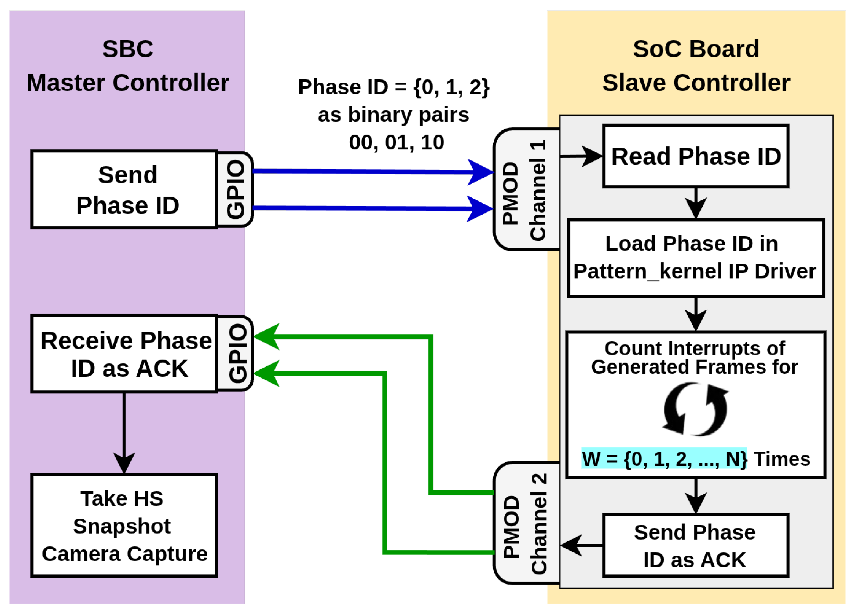
Figure 4 shows an abstract diagram of how synchronization can be achieved. The SBC asks the SoC to generate and stream pattern frames for a particular phase ID through a GPIO request using two wires. The SoC board receives this ID through the PMOD port and instructs the
Pattern_kernel IP to load the pattern for this particular phase ID. The IP then starts counting the interrupts emitted by the generated frames
W times until the pattern frame is initialized and stabilized on the projection surface by the DLP projector.
W is sent by the SBC master controller application (implemented through the
sendWaitFrameCountToSoC(W) function, which is provided for reference in the (
Appendix B.5, Algorithm A2). After that, the SoC board sends an ACK using the other two wires to the SBC. After receiving the ACK, SBC takes an HS image capture.
To control and count the generation of individual pattern frames, the SW system running on the SoC PS must know when a pattern frame is generated by the
Pattern_kernel IP. To achieve this, an interrupt must be sent from the
Pattern_kernel IP to the PS IP after the completion of one-frame generation.
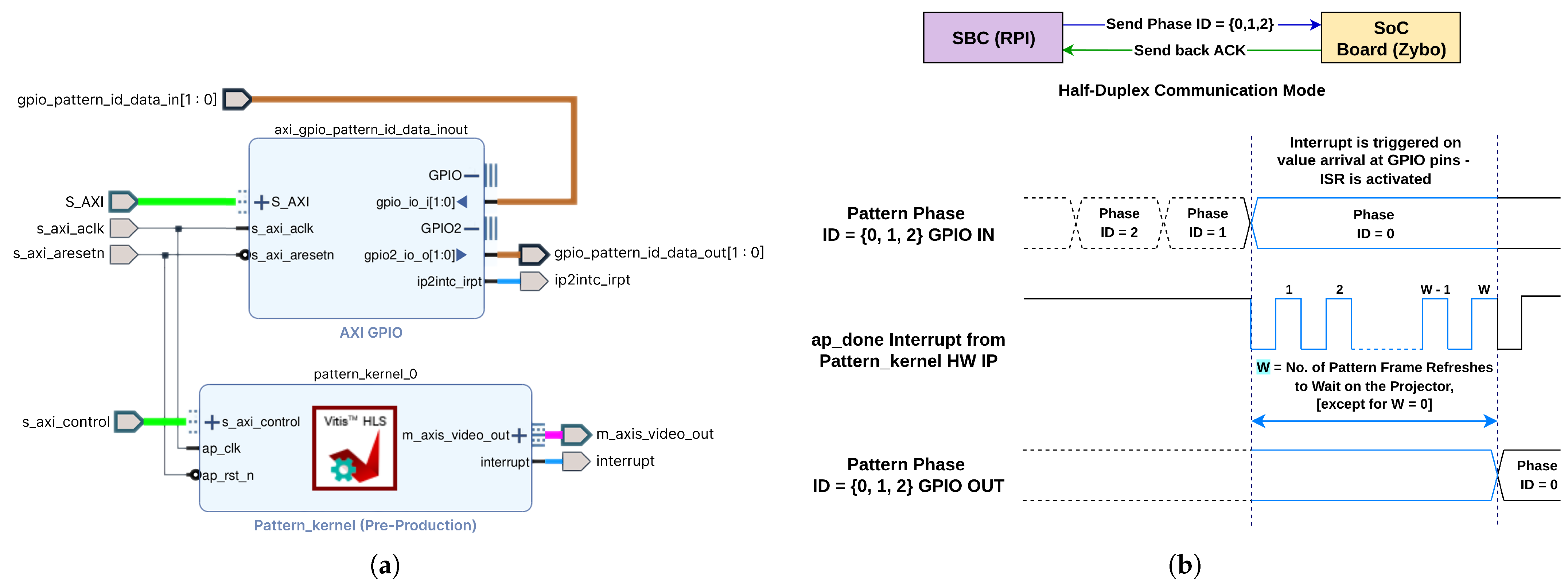
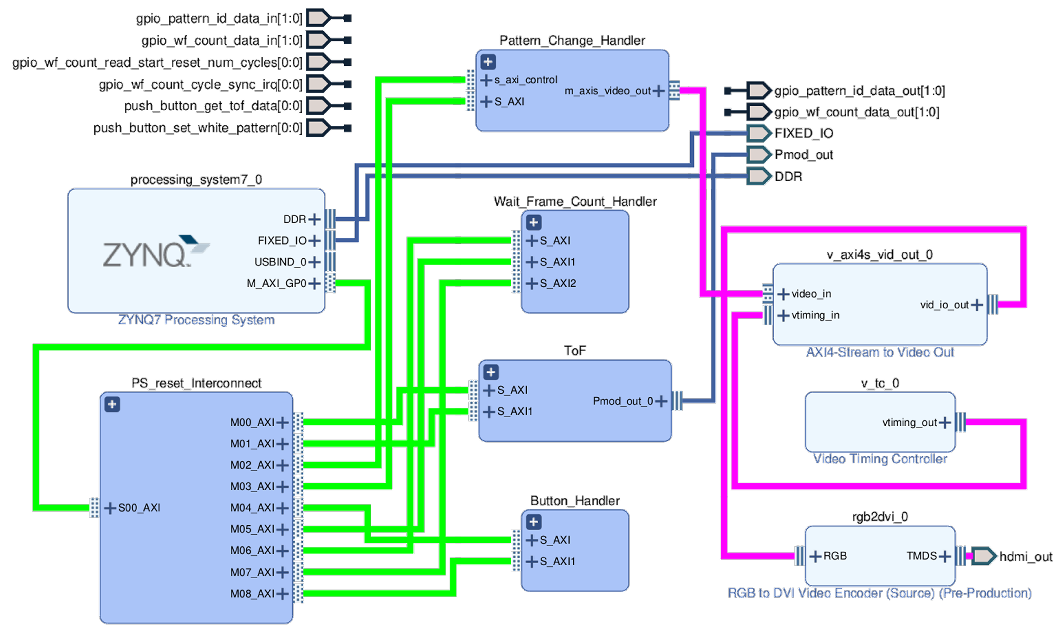
Figure 7a zooms in on the
Pattern_Change_Handler group of the HW design (provided as a reference in the
Appendix B.4.5,
Figure A8, for further explanation), where the interrupt port can be seen on the
Pattern_kernel IP. The interrupt port is connected to the PS. Also, the
AXI GPIO IP from this group is responsible for the GPIO connection with the SBC GPIO pins through the SoC board’s PMOD port. The interrupt mode is enabled on the GPIO IP as well.
On the SoC board, the receiving GPIO pair for the phase ID is grouped into Channel 1, and the ACK sending pair is Channel 2. A separate pair of GPIO pins is implemented so that receiving and sending do not conflict with each other, ensuring technical simplicity.
Figure 7b also shows that a simplified GPIO dataflow occurs between the SBC and the SoC, while interrupt-signal management takes place inside the SoC. It describes how different values of
W (except
W = 0) are managed with respect to the interrupt-handling mechanism. The SBC transmits an integer phase ID =
as the binary bit combination of 00, 01 and 10; each bit is sent over a pair of wires. The SBC can send only one phase ID at an arbitrary moment, which means that a request can occur at any moment in time. As complete communication between the SBC and SoC takes place in half-duplex mode, after making this GPIO request, the SBC waiting period begins. When the
AXI GPIO IP (
Figure 7a) sees changes in the PMOD pins of
Channel 1, it emits an internal interrupt. This interrupt causes the execution of an ISR as a callback, as given in the self-documented pseudocode in Algorithm 1.
The SBC writes to its own GPIO pins sequentially. The first write immediately triggers an interrupt on the SoC and invokes the ISR. A static delay of 8 ms has been added on line 3 (i.e.,
WAIT(8 milliseconds)) so that the SBC can complete the writes to both pins. This static delay was found through trial and error. Every time the
Pattern_kernel IP completes its execution, it emits an
ap_done interrupt. As the IP is always running, the interrupt signal will always be high, as can be seen in the timing diagram in
Figure 7b. Line 11 of the ISR Algorithm 1 cleans that first. So in the timing diagram, it can be seen that it goes down at the beginning, as shown by the signal at the
ap_done interrupt from the
Pattern_kernel HW IP. Line 12 has the
for loop that runs for
W tripcounts.
The
Pattern_kernel IP is controlled from the PS (i.e., from the ISR) through IP control registers. Different control registers are checked by the IP at the IP boot and runtime to perform different control tasks. At line 7,
DISABLE_AUTO_RESTART(pattern_kernel) writes a Boolean false value to the
Pattern_kernel IP’s auto-restart control register. Once the existing frame (i.e., the previous phase before changing to the new phase) finishes, the
Pattern_kernel IP sees the false value and stops auto-restarting the IP. Next, at line 8, the IP control registers are updated with the new phase ID as the SBC requested through the GPIO. At line 9, auto-restart is enabled again. This causes the IP to begin generating frames for the new phase ID. All three writes to the correspondent registers complete in microseconds, and this delay is considered negligible in performance measurements.
| Algorithm 1 Handle_Phase_Id_Change_Request ISR |
1: function Handle_Phase_Id_Change_Request
2: // 1. Wait to ensure both input pins have settled
3: WAIT(8 milliseconds)
4: // 2. Read the new pattern ID from GPIO channel 1
5: receivedPhaseId ← READ_GPIO(channel = 1)
6: // 3. Update the pattern generator IP
7: DISABLE_AUTO_RESTART(pattern_kernel)
8: SET_PHASE(pattern_kernel, phases[receivedPhaseId])
9: ENABLE_AUTO_RESTART(pattern_kernel)
10: // Clear any stale “done” flags and then wait for W frame count
11: CLEAR_INTERRUPT(pattern_kernel, AP_DONE_INTERRUPT_MASK)
12: for to do
13: while (GET_INTERRUPT_STATUS(pattern_kernel) & AP_DONE_INTERRUPT_MASK) ≠ AP_DONE_INTERRUPT_MASK do
14: // wait until AP_DONE interrupt is emitted
15: end while
16: CLEAR_INTERRUPT(pattern_kernel, AP_DONE_INTERRUPT_MASK)
17: end for
18: // 5. Send the acknowledgment back on GPIO channel 2
19: WRITE_GPIO(channel = 2, value = receivedPhaseId)
20: // 6. Finally, clear the GPIO interrupt flags
21: CLEAR_GPIO_INTERRUPT(mask)
22: end function |
Since the SBC phase-change request can arrive through GPIO at any moment, even while the IP is still generating the frame of the previous phase, an interrupt (possibly residual) could be emitted when this last frame finishes. This approach guarantees that the pattern stream never halts, at the minor cost of measuring one interrupt from the old phase. This phenomenon was investigated and verified through an experiment, as described in
Section 5.5.3. Subsequently, as presented in the same section, the first interrupt period measurement equations were derived and calculated using the runtime performance data across different
W configurations.
At line 13, the
while loop checks for the
ap_done interrupt coming from the
Pattern_kernel IP. Then the
ap_done interrupt register is cleared again so that, in the next
for loop iteration, it can be checked again. This is why in the timing diagram
Figure 7b, a repetitious pattern of the square wave can be seen to occur
W times as the
for loop runs for
W tripcounts. After finishing the
for loop, the received phase ID is written as an ACK value to GPIO
Channel 2 at line 19. Finally, the
AXI GPIO interrupt is cleared at line 21 so that it can be ready to detect the interrupts when the next phase ID arrives. For the case of
W = 0, the ISR skips the entire
for loop and jumps directly to line 19 to send the ACK.
The GPIO API in the SBC can detect changes in GPIO ACK pins that are connected to Channel 2 of the SoC board by continuous polling. After receiving the ACK, the SBC takes and saves the HS image capture and prepares to send the next phase ID.
6. Discussion
This research begins with studying the SOTA HSPy-SI projection–capture synchronizer system. It then proposes a successful design and development methodology for a high-performance, configurable, real-time SI synchronizer system, named the HyperSI system. Both systems follow the conventional TPD method to implement the SI principle and use the same UVC-compliant HS snapshot camera and DLP projector model that supports HDMI video mode. The chosen DLP projector introduces a one-frame projection (i.e., display) delay due to its dual-buffer mechanism. Hence, both systems must compensate for this delay to achieve accurate projection–capture synchronization. The SOTA system handles all core tasks, including frame generation, pattern phase transitions, HDMI streaming to the DLP projector, and camera capture. In contrast, the proposed HyperSI system distributes these tasks across two dedicated computing platforms: an SBC to control the change of pattern and capture image, and an SoC for high-performance pattern generation. Thus, the SBC acts as the master controller, managing the slave SoC-based system through GPIO communication. Both systems use a DMD-based DLP projector to project three-phase patterns, with HDMI input and video mode as required specifications.
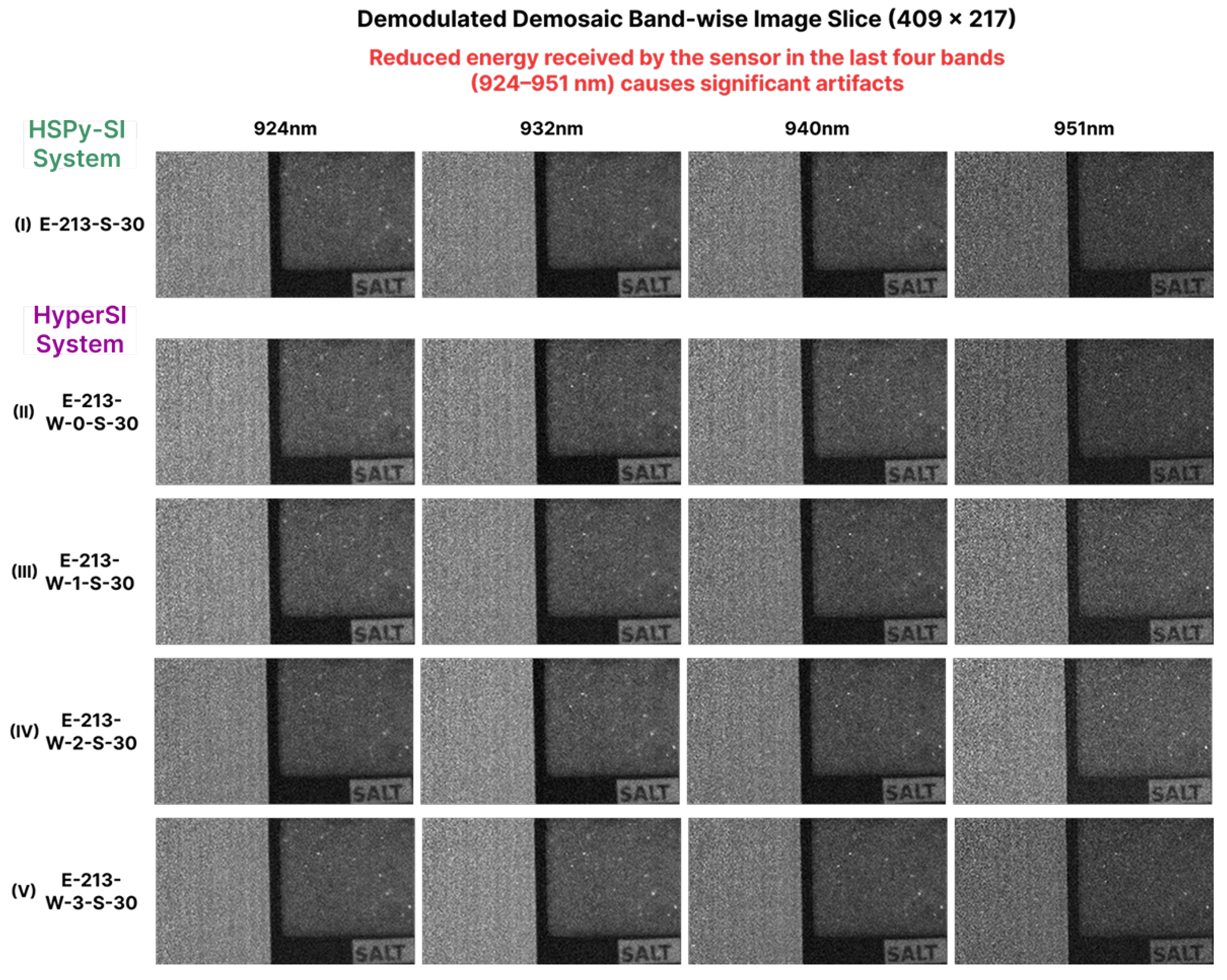
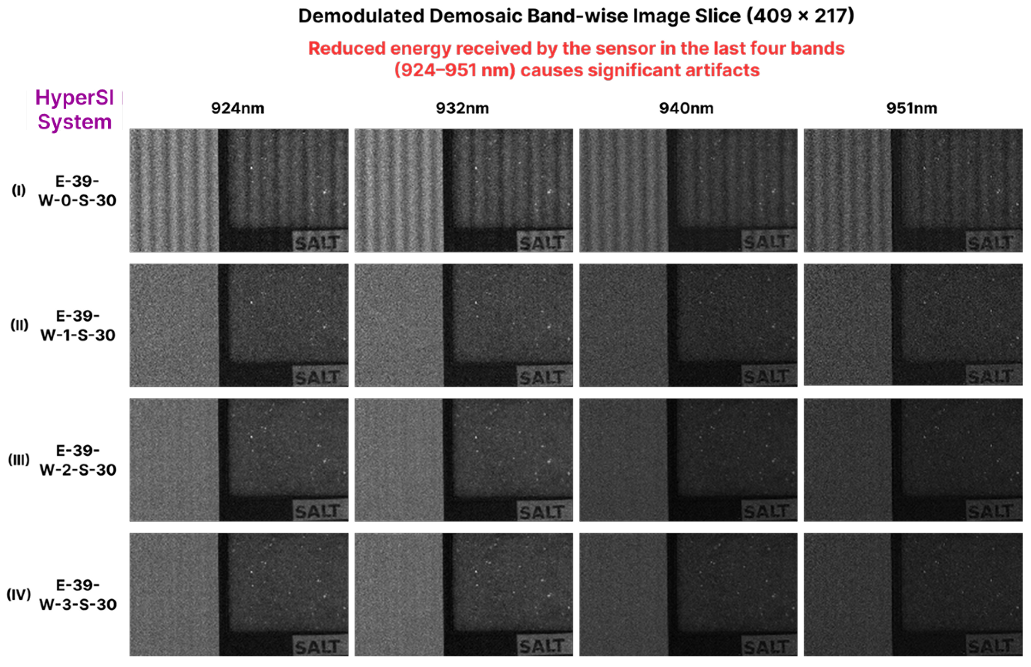
Two camera exposure settings, one with a polarizer and one without (i.e., no-polarizer setting), are used to capture modulated images across three phases. The SOTA HSPy-SI system can capture modulated images only when using polarizers, which require a longer exposure time (i.e., 213 ms). This limitation arises because the system relies on a desktop computer for both frame generation and synchronization, lacking the low-level hardware access needed for accurate frame-level control. As a result, to address the one-frame projection latency caused by the DLP projector, the synchronizer delay was determined only for the polarizer configuration (i.e., the longer, 213 ms exposure) using a trial-and-error approach within a large search space. In contrast, the proposed HyperSI system offers greater flexibility in capture configurations by supporting both polarizer and no-polarizer settings (i.e., shorter 39 ms of exposure). This is because it uses a dedicated SoC-based frame generator with direct low-level HW access. This design allows for precise control over each 24-bit RGB pattern frame generation at approximately 58 Hz, about 8× faster than the SOTA HSPy-SI system. The pattern quality is validated by achieving zero RMSE compared to reference patterns generated using 64-bit floating-point precision on an Intel processor. To accurately address frame-level projection latency (i.e., one-frame display delay), the proposed system introduces a configurable W parameter implemented in the SoC as a projection–capture synchronization tuner, configurable from the SBC controller. The W parameter sets how long (i.e., in terms of the number of generated pattern frames) the SBC waits before triggering the camera capture. During this time, the SoC counts the corresponding number of frame-generation interrupts. Hence, it was necessary to verify that the interrupt period I matches the measured frame period (i.e., ). This was experimentally confirmed, where the measured interrupt period of ms closely matched the oscilloscope measurement of ms. A small deviation was observed for the first interrupt, which originated from a frame of the previous phase but remained within a predictable range of to ms (except for one outlier measured as ms) during the capture experiment.
This study presents an end-to-end methodology in which the SoC-based system was developed through a structured, reproducible, step-by-step HW/SW co-design process. The method for determining the core HW clock (i.e., 86 MHz) and configuring the VTC parameters adheres to the VESA standard. This ensures adaptability at a resolution of and an FRR of approximately 58 Hz (targeting 60 Hz), providing compatibility with VESA-compliant display devices for HDMI I/O. In particular, the HDMI interface support makes this system projector-model-agnostic. A comprehensive methodology has been established to design the parameterized pattern-generator IP using a dataflow MoC implemented through HLS. This approach enables real-time, high-performance pattern streaming with 1 PPC. The HW design illustrates how key IP cores, including the pattern generator, VTC, and AXI GPIO modules, are integrated to support the functional requirements of the embedded SoC controller. Furthermore, it outlines the ISR algorithm, which is triggered by the SBC via GPIO, to change the pattern and implement a configurable frame-generation-based interrupt delay according to the specified W count. Meanwhile, a simple SBC algorithm was developed to serve as the master controller to manage the SoC system. This manages camera capture and controls pattern phase changes on the SoC via GPIO communication. Since the UVC-compliant HS snapshot camera is connected via a USB interface to the SBC, the system remains compatible with any snapshot camera that supports the UVC standard.
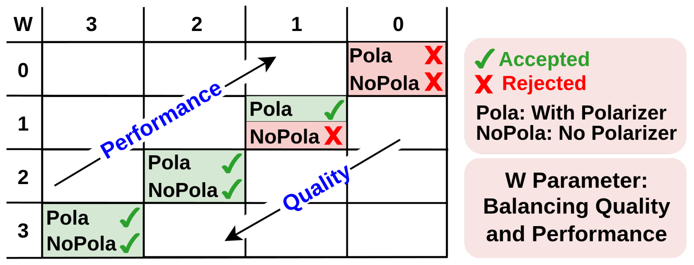
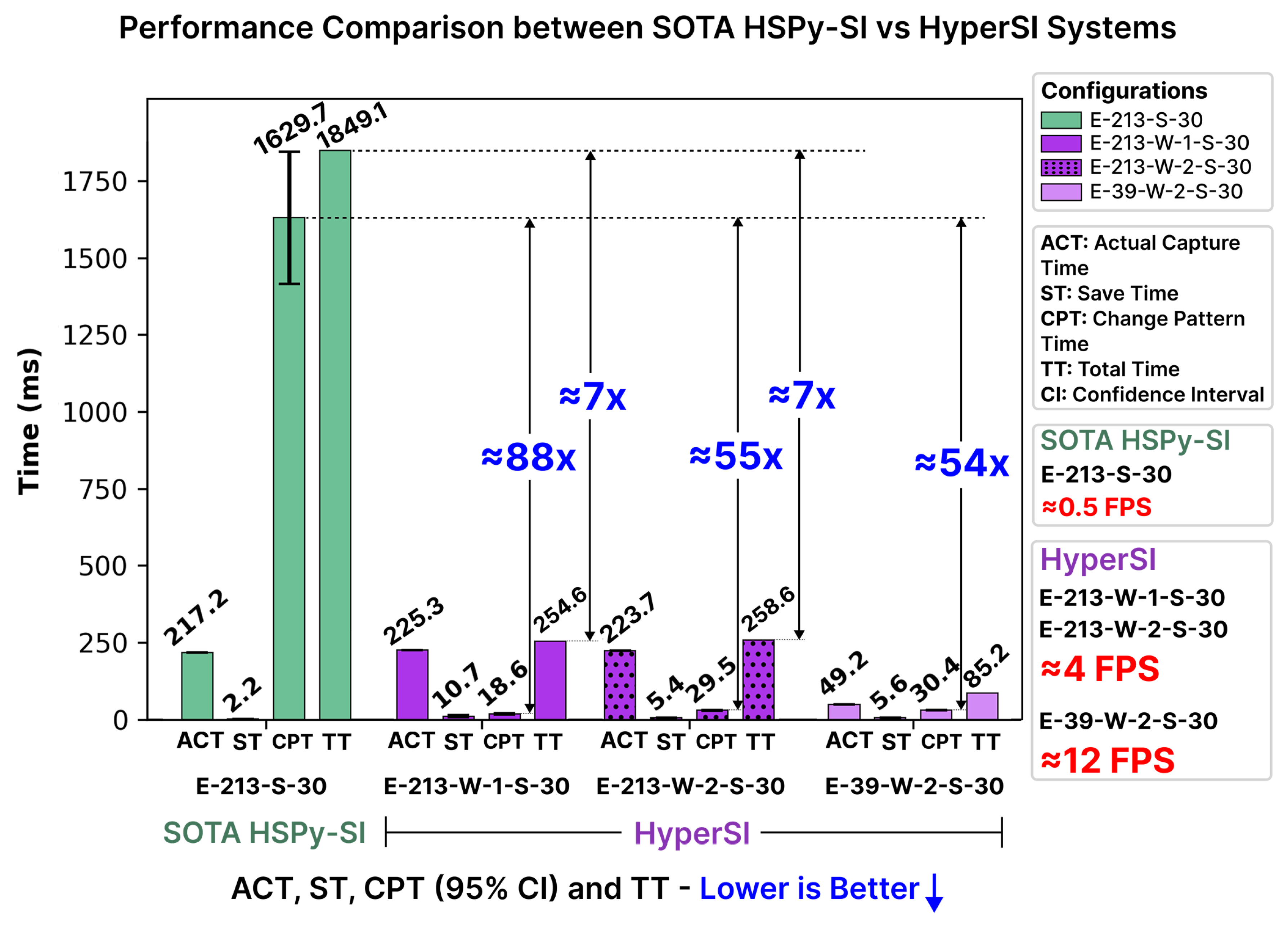
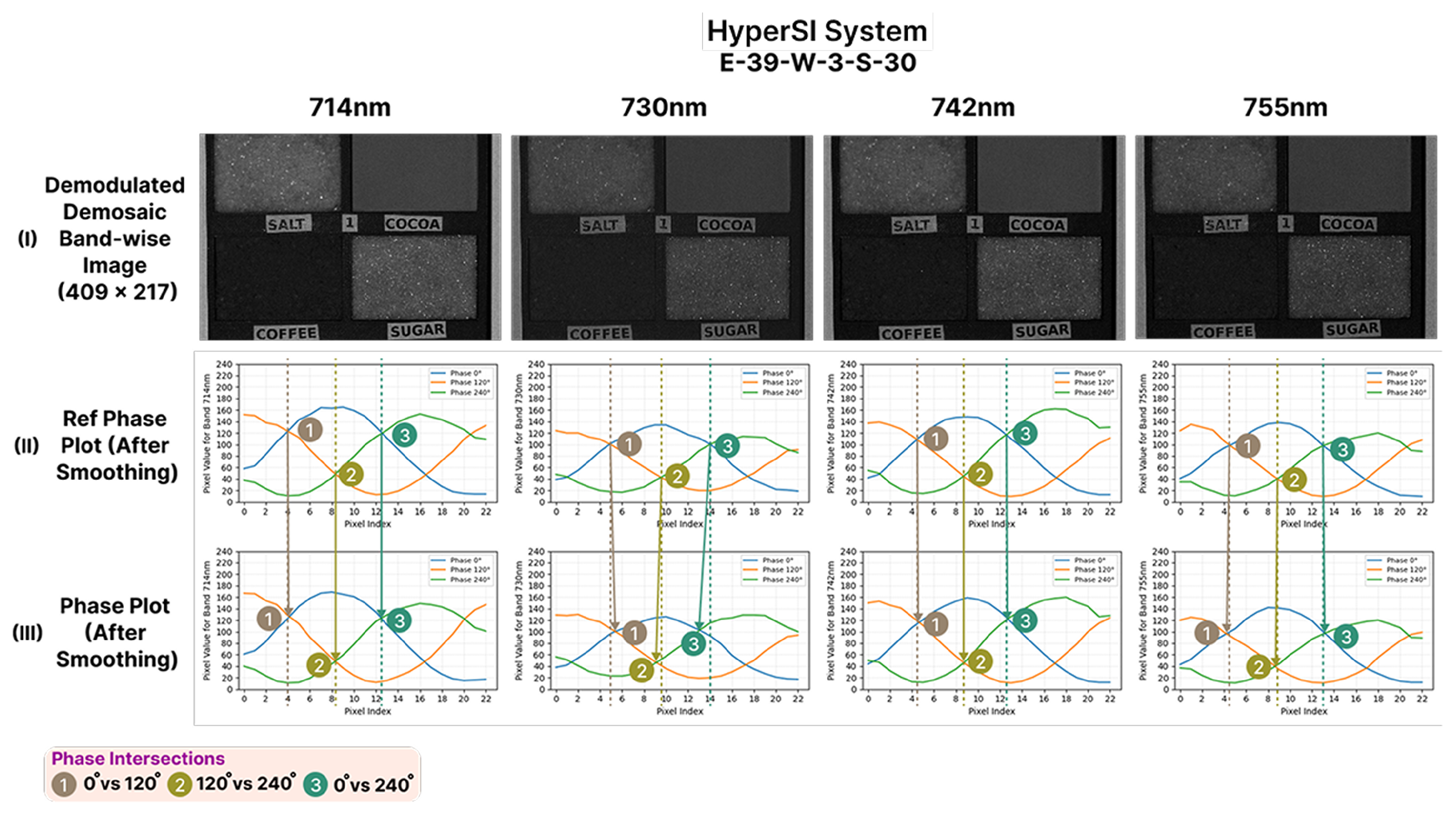
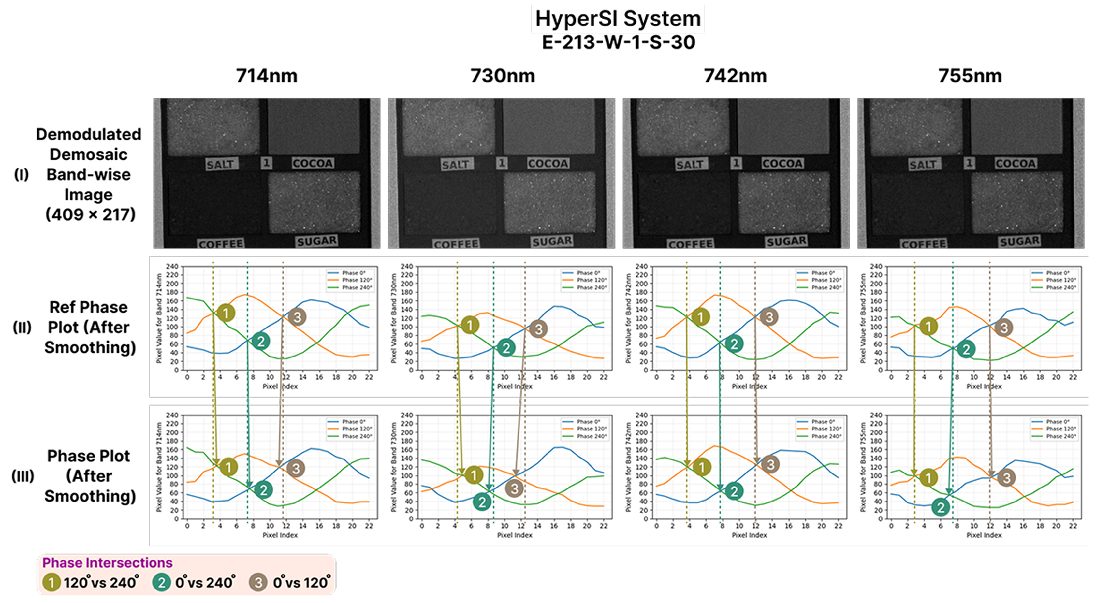
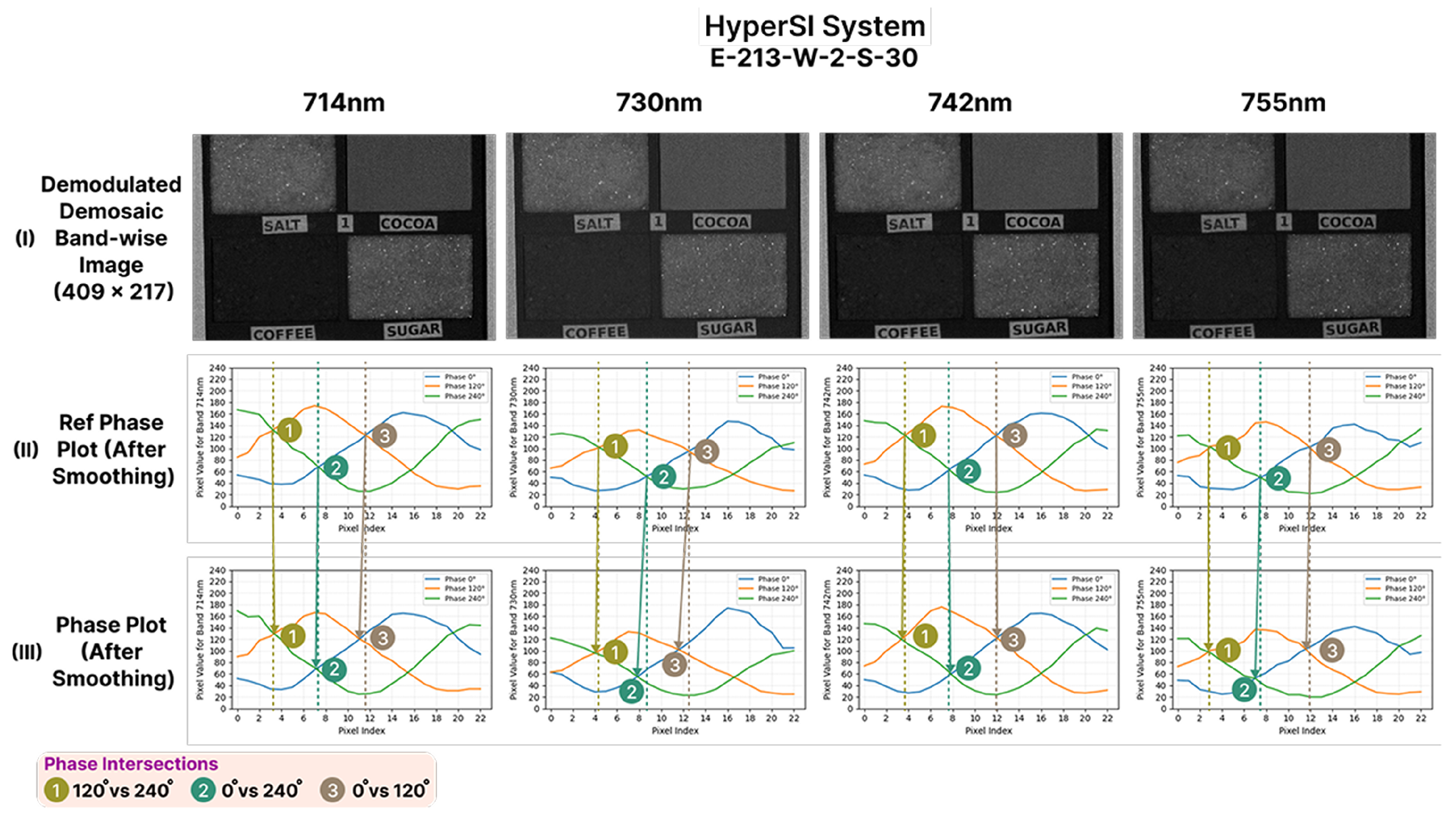
Evaluation is an integral part of the proposed methodology, for which specific criteria have been defined to evaluate the demodulated images produced by both the SOTA HSPy-SI and HyperSI systems. The modulated images captured by both systems, across all configurations, were compared with the reference captures. The evaluation was conducted on the basis of the quality of the resulting demodulated images and their corresponding phase plots. Modulated image captures were performed using a polarizer with the SOTA HSPy-SI synchronizer. Unlike the SOTA system, the captures performed by the proposed HyperSI system are directly influenced by the parameter W. Hence, multiple capture configurations of the proposed system were explored by varying the tunable parameter W in the range of 0 to 3. The phase transition from P0 to P1 was selected as the candidate modulated capture for the evaluation of both systems. Based on the evaluation criteria, three optimal configurations (i.e., with minimum acceptable W values) were identified for the proposed system: E-213-W-1-S-30 and E-213-W-2-S-30 for the polarizer setting, and E-39-W-2-S-30 for the no-polarizer setting. Under the polarizer setting, the SOTA system recorded a CPT of ms. In contrast, the proposed system achieved significantly faster performance, with CPTs of ms for W = 1 and ms for W = 2. These correspond to performance improvements of roughly 88× and 55×, respectively. Although the SOTA HSPy-SI system captured roughly one modulated frame every two seconds, the proposed system reached a capture rate of approximately 4 FPS. The greatest improvement in FPS was observed in the no-polarizer setting in the proposed system, where it was close to 12.
The demodulation analysis in this study was based on two explicitly defined acceptance criteria: first, that at least two of the pre-selected bands exhibit phase shifts closely aligned with the reference vertical guides of the reference SPP, and second, that the resulting demodulated images remain free of visible noise or artifacts. In parallel, a deterministic synchronization analysis of the proposed system indicated that the conservative safe operating range for the delay parameter W is approximately 3 to 4. These two analyses serve different purposes: the deterministic W range defines a safer synchronization margin from a system-timing perspective, whereas the demodulation criteria evaluate whether the captured data are practically sufficient to produce acceptable image quality. Therefore, the fact that some lower W values also produced acceptable demodulation does not imply that the criteria were weak; rather, it shows that the system can still tolerate certain non-ideal synchronization conditions while maintaining acceptable output quality. Hence, the lower acceptable values of W do not indicate that the evaluation criteria were too weak. Rather, they show that there is a difference between the minimum deterministic safe synchronization value and the minimum experimentally acceptable value for demodulation. The calculated W = 3 to 4 range represents a conservative synchronization setting derived from the projector–camera timing model so that the camera capture is more safely aligned with the intended projected phase. In contrast, the experimental results show that acceptable demodulation can still occur at lower W values when the captured signal contains a sufficient proportion of the correct-phase information and the demodulated image remains free of visible noise or artifacts. This is exactly what was observed in the reported results. For example, under the no-polarizer condition, E-39-W-2-S-30 produced acceptable demodulation even though W = 2 is below the conservative deterministic range, because the camera still captured about 56% correct-phase information, and the demodulated output satisfied the visual acceptance criteria. By contrast, under the polarizer condition, E-213-W-0-S-30 failed, even though about 81% correct-phase information was present, because the reduced light energy degraded the modulated image and therefore demodulated image quality. However, E-213-W-1-S-30 became acceptable (i.e., with an increase of just 4% correct-phase data) with approximately 85% correct-phase information. These results show that acceptable demodulation depends not only on phase correctness but also on signal energy behavior. Therefore, the purpose of the evaluation criteria was not only to redefine the deterministic synchronization bound but also to establish a practical benchmark for understanding how different synchronization conditions affect what the camera actually records and how that, in turn, affects demodulation quality. In this sense, the calculated W = 3 to 4 values provide safer and more deterministic operating points, whereas the lower experimentally acceptable W values reveal the tolerance of the system under less conservative conditions. This is a useful finding rather than a weakness of the criteria, because it shows that the proposed study not only identifies a deterministic synchronization setting but also characterizes the trade-off between acquisition speed and demodulation quality. This level of insight is important for users who may wish to choose between a more conservative synchronization margin and a faster operating point depending on the imaging scenario.
Since one of the central claims of this work is that the proposed HyperSI synchronizer is designed as a compact and portable embedded prototype, its physical form factor should be compared against the desktop-based synchronizer used in the SOTA HSPy-SI system. This comparison is important because the form factor directly affects system integration, portability, setup complexity, and suitability for space-constrained experimental environments. Using the approximate dimensions from
Section 4.3, the proposed embedded synchronizer consists of an RPI 4 Model B with a volume of
and a Zybo Z7-20 SoC board with a volume of
, giving a total bare-board volume of
. If a packaging tolerance of 200% is included to account for enclosure space, wiring, connectors, and support integration overhead, the effective volume of the embedded synchronizer becomes
, which is equivalent to approximately
. In contrast, the SOTA HSPy-SI synchronizer described in
Section 3.1 uses a desktop with an approximate volume of
, or
. Therefore, even after accounting for the 200% enclosure tolerance, the proposed embedded architecture reduces the synchronizer volume by approximately 96.7% relative to the desktop-based SOTA system, demonstrating a substantial improvement in compactness and portability.
The present prototype has been experimentally validated at a single spatial frequency of , and the claims made in this manuscript are therefore restricted to single-frequency operation. However, the proposed HyperSI pattern-generator hardware IP was intentionally designed as a parameterized and deterministic real-time video-streaming block, in which runtime arguments such as spatial_frequency do not alter the synthesized throughput of the design. Since the hardware maintains 1 PPC operation at an 86 MHz clock for a fixed projector resolution, the frame-generation timing remains deterministic for the implemented architecture across the supported spatial frequency parameter range of . In addition, the DLP projector operates in video mode by locking to the incoming HDMI frame timing and maintaining its deterministic dual-buffer latency mechanism, which depends on frame timing rather than on the spatial content of the projected pattern. Therefore, although multi-frequency performance has not yet been experimentally demonstrated in this manuscript, the proposed prototype already possesses the architectural capability to support future experiments with multiple spatial frequencies without modification of the synchronization framework.
Table 2 includes different approaches using SI and multi-spectral or HS imaging acquisition systems to be compared in terms of their acquisition time. The table includes the citation of the study where the system is described, the year it was published, how many spatial frequencies were used, the number of wavelengths measured as well as the spectral range, how many phases or patterns were used for every wavelength, the total number of images projected and captured, the amount of time necessary to acquire all projected patterns, and the synchronizer system-build form factor. Note that the column “phases per wavelength” refers to how many patterns of SI were used per wavelength measured.
Table 2 shows that HyperSI occupies a distinct position among existing SFDI systems by combining the conventional TPD workflow, broad HS coverage, and an explicitly engineered frame-level synchronizer within a compact embedded architecture. Compared to earlier TPD-based systems, which typically use 2–11 spatial frequencies, 4–34 wavelengths, and acquisition times ranging from 3.6 s to 150 s per dataset [
19,
20,
22,
23,
31], HyperSI retains the standard TPD model while reducing the modulated acquisition rate (i.e., in FPS) by achieving 12 modulated HS cubes per second over 24 bands from 660 to 950 nm for one experimental spatial frequency. This makes it, to the best of the authors’ knowledge and among the studies compared in
Table 2, the fastest reported TPD-based HS SFDI synchronizer while still preserving conventional TPD. In contrast, the higher-speed systems in the literature achieve their rates mainly by departing from the TPD itself, for example, through SSOP, cSFDI, or temporally multiplexed single-pattern acquisition [
16,
30,
54]. Although such approaches provide clear speed advantages, they trade away the conventional TPD framework and are therefore subject to the known limitations of single-shot methods, including lower spatial resolution, edge artifacts, motion sensitivity, and reduced reconstruction fidelity compared with phase-stepped SFDI (
Section 1). HyperSI instead addresses speed without abandoning TPD while also providing a synchronizer form factor that is qualitatively different from those of prior desktop-, cart-, and SW-sequenced systems [
19,
20,
22,
23]. Furthermore, the pattern-generator IP in the SoC exposes the arguments
tof_distance,
phase,
spatial_frequency,
throw_ratio, and
brightness as scalar control registers through an AXI4-Lite slave interface. As a result, these parameters are configurable at runtime from the embedded application in the PS, rather than being fixed constants in hardware. Although the present experiment was conducted using only one spatial frequency, the parameterized IP design allows the same hardware to be reconfigured for different spatial frequencies in future experiments, together with the other exposed parameters, without requiring hardware redesign. Its decoupled portable embedded synchronizer, compatibility with HDMI- and USB-based projection-imaging setups, deterministic frame-level synchronization, and tunable compensation for projector dual-buffer latency together make it more viable for TPD-based real-world applications, where compactness, timing determinism, interoperability, and real-time operation are all important.
To the best of the authors’ knowledge and based on the studies summarized in
Table 2, HyperSI represents the fastest reported implementation of the TPD-based portable bench-top real-time SI prototype in terms of modulated capture rate while also providing explicit frame-level synchronization with the tunable delay control parameter
W. Unlike previous TPD-based implementations that typically rely on fixed SW delays, the proposed system explicitly guarantees frame-level projection–capture synchronization, enabling deterministic and configurable timing control during acquisition.





 ,
,