

On-Ground Testing of Dual-Sided Release Mechanism of TianQin Test Mass Using a Pendulum

 , , ,
, , ,
Abstract
1. Introduction
2. The Locking-and-Release Mechanism of TianQin
2.1. The Purpose of Locking and Releasing
2.2. The Main Structure of the Locking-and-Release Mechanism
2.3. The Requirements for the TM Release
3. The On-Ground Testing of the TM Released on Both Sides
3.1. Basic Principle of On-Ground Testing
3.2. Structure of the Release Mechanism
3.3. Design of Measurement
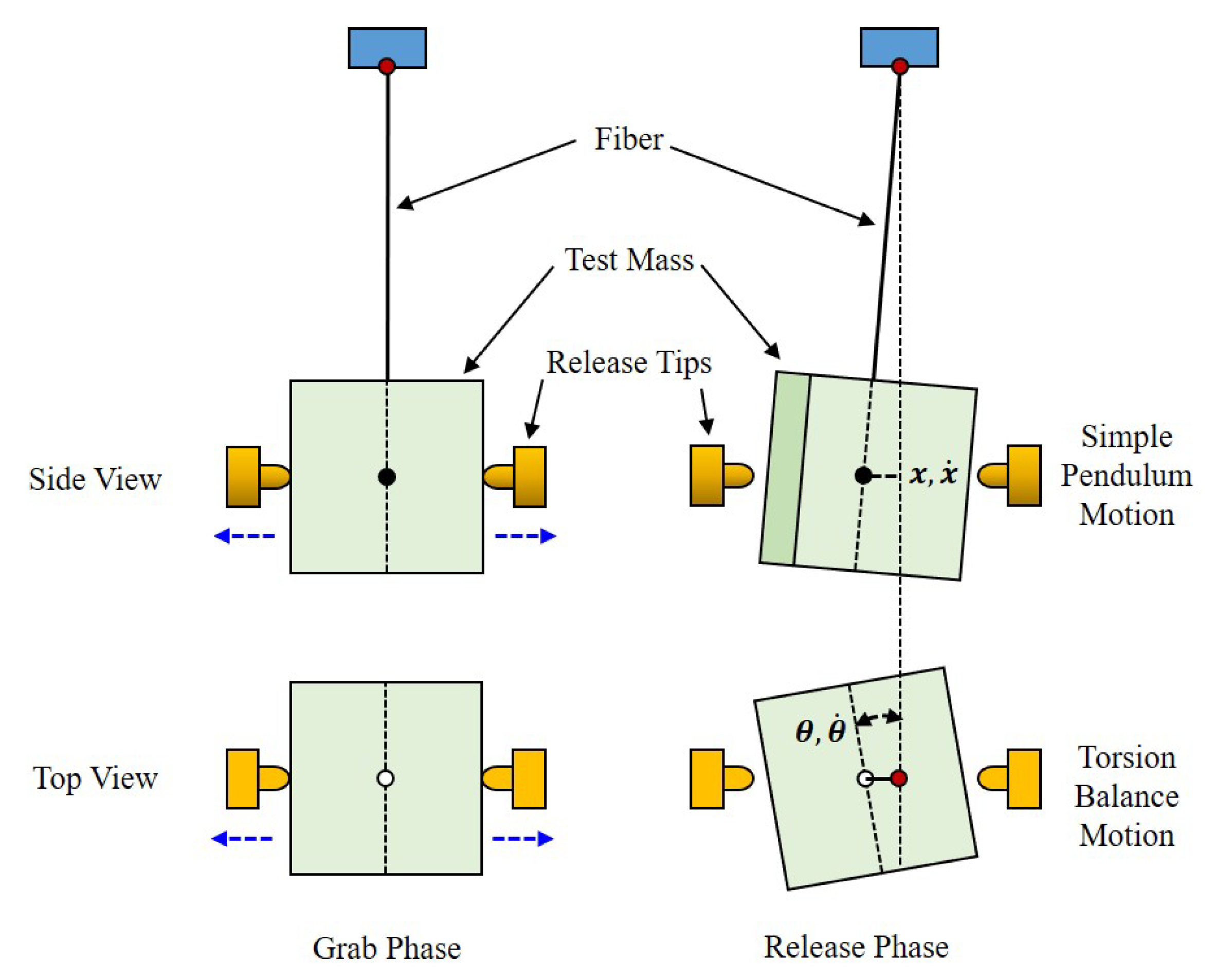
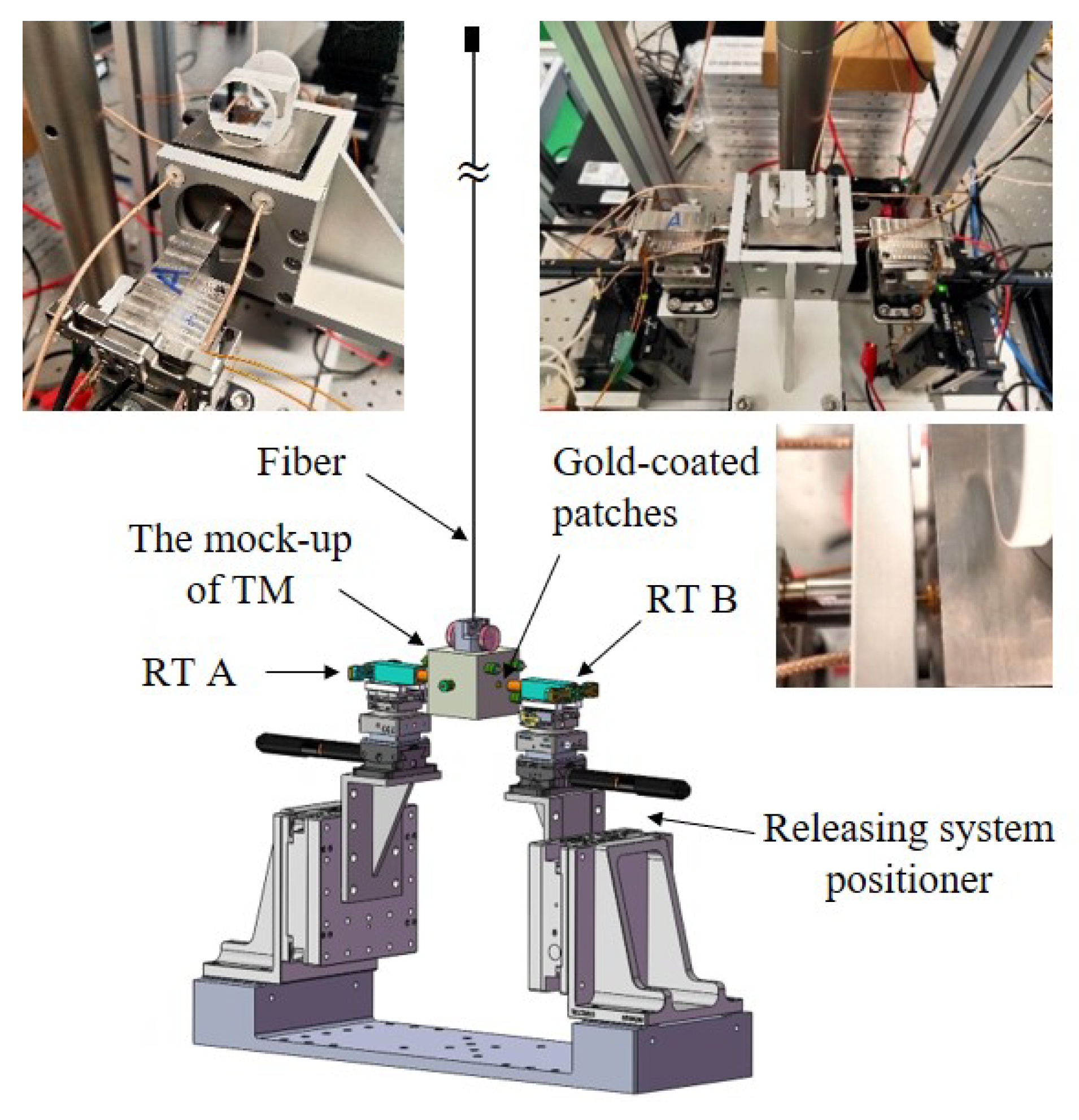
- The suspended mock-up of TM: A tungsten cubic block with a length of 49.926(1) mm, width of 50.100(1) mm, and height of 50.089(2) mm is used as the TM, which is suspended by a tungsten fiber measuring 200 m in diameter and 920 mm long. In order to ensure that the contact conditions between the surfaces of the TM and RT remain consistent with the on-orbit, the gold-coated patches are equipped on both sides of the TM. The total mass of the mock-up of the TM is 2375.005(1) g. The theoretical periods of oscillation of the simple pendulum motion and the torsion balance motion are 1.928(5) s and 38.5(2) s, respectively. Furthermore, different masses of the mock-up of the TM have also been employed to verify the release mechanism.
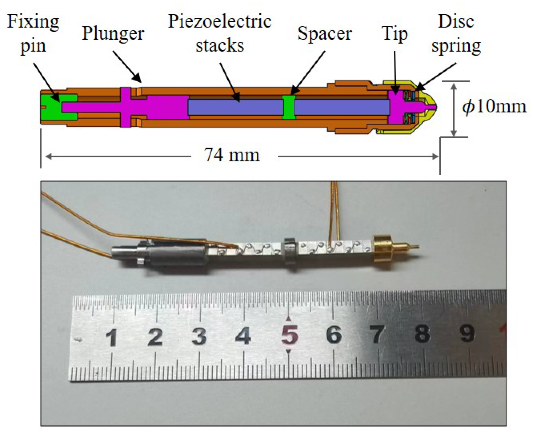
- The release mechanism: The structure of the release mechanism is designed and shown in Figure 5. Two RTs are actuated using a piezoelectric stack to make contact with the TM mock-up from both sides. Subsequently, the RT is quickly retracted to release the suspended TM.
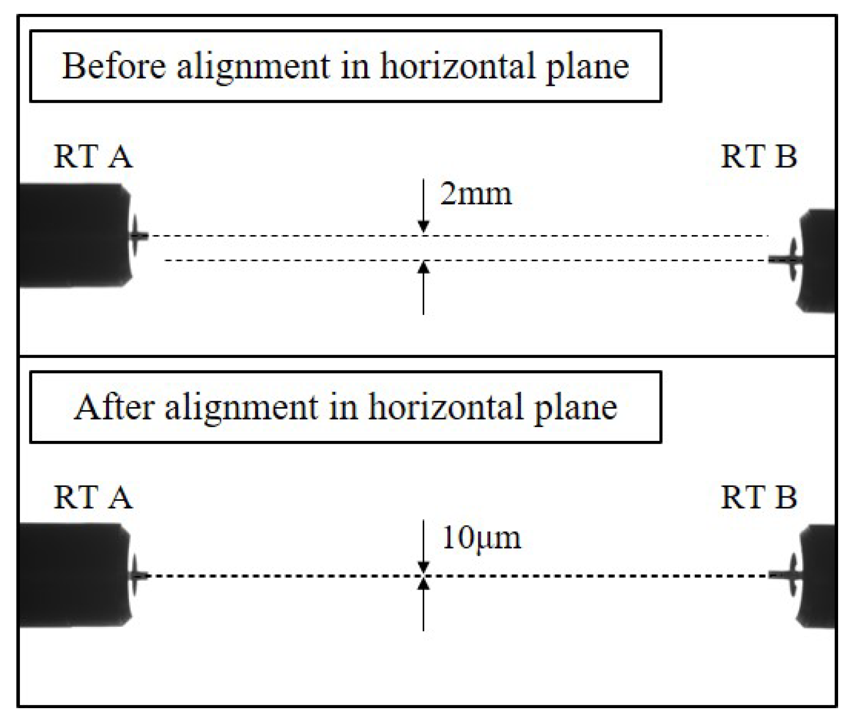
- Releasing system positioner: The alignment of the release mechanisms on both sides, as well as the alignment between the release mechanisms and the TM, is accomplished using displacement stages and rotary stages with a resolution of 0.01 m and 50 arcsec, respectively.
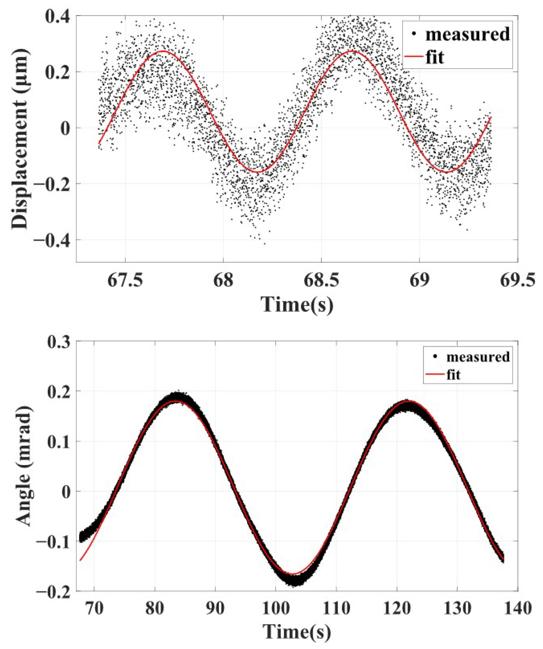
- Measurement system: The multiple eddy current displacement sensors are distributed on both sides of the TM to jointly measure the translational and rotational signals of the TM. Each sensor achieves a measurement resolution of 0.1 m. An autocollimator is utilized to measure the pitch and yaw signals of the TM, providing a measurement accuracy of ±0.2 arcsec. The measurement resolution and the accuracy mentioned above are determined based on the fundamental principles of ground testing, reaching a momentum of and an angular momentum of , which ensures measurement redundancy.
- Testing environment: The on-ground testing platform is placed on an optical isolation table to effectively isolate the influence of ground vibrations. The entire setup is enclosed in an acrylic enclosure to mitigate the effects of gas flow. A thermometer with an accuracy of 0.01 °C is utilized to concurrently monitor temperature variations throughout the experimental procedure.
3.4. Experimental Preparation
4. Results
5. Discussion
Author Contributions
Funding
Institutional Review Board Statement
Informed Consent Statement
Data Availability Statement
Conflicts of Interest
References
- DeBra, D.B.; Conklin, J.W. Measurement of Drag and Its Cancellation. Class. Quantum Gravity 2011, 28, 094015. [Google Scholar] [CrossRef]
- Everitt, C.W.F.; DeBra, D.B.; Parkinson, B.W.; Turneaure, J.P.; Conklin, J.W.; Heifetz, M.I.; Keiser, G.M.; Silbergleit, A.S.; Kolodziejczak, J.; Al-Meshari, M.; et al. Gravity Probe B: Final Results of a Space Experiment to Test General Relativity. Phys. Rev. Lett. 2011, 106, 221101. [Google Scholar] [CrossRef]
- Huang, T.; Lühr, H.; Wang, H.; Xiong, C. The Relationship of High-Latitude Thermospheric Wind with Ionospheric Horizontal Current, as Observed by CHAMP Satellite. J. Geophys. Res. Space Phys. 2017, 122, 12378–12392. [Google Scholar] [CrossRef]
- Tapley, B.D.; Bettadpur, S.; Watkins, M.; Reigber, C. The Gravity Recovery and Climate Experiment: Mission Overview and Early Results. Geophys. Res. Lett. 2004, 31, GL019920. [Google Scholar] [CrossRef]
- Drinkwater, M.R.; Haagmans, R.; Muzi, D.; Popescu, A.; Floberghagen, R.; Kern, M.; Fehringer, M. The GOCE Gravity Mission: ESA’s First Core Earth Explorer. In Proceedings of the 3rd International GOCE User Workshop, Frascati, Italy, 6–8 November 2006; Volume SP-627, pp. 1–8. [Google Scholar]
- Touboul, P.; Rodrigues, M. The MICROSCOPE Space Mission. Class. Quantum Gravity 2001, 18, 2487–2498. [Google Scholar] [CrossRef]
- Hudson, D.; Chhun, R.; Touboul, P. Development Status of the Differential Accelerometer for the MICROSCOPE Mission. Adv. Space Res. 2007, 39, 307–314. [Google Scholar] [CrossRef]
- Armano, M.; Benedetti, M.; Bogenstahl, J.; Bortoluzzi, D.; Bosetti, P.; Brandt, N.; Cavalleri, A.; Ciani, G.; Cristofolini, I.; Cruise, A.M.; et al. LISA Pathfinder: The Experiment and the Route to LISA. Class. Quantum Gravity 2009, 26, 094001. [Google Scholar] [CrossRef]
- Jennrich, O. LISA Technology and Instrumentation. Class. Quantum Gravity 2009, 26, 153001. [Google Scholar] [CrossRef]
- Antonucci, F.; Armano, M.; Audley, H.; Auger, G.; Benedetti, M.; Binetruy, P.; Boatella, C.; Bogenstahl, J.; Bortoluzzi, D.; Bosetti, P.; et al. LISA Pathfinder: Mission and Status. Class. Quantum Gravity 2011, 28, 094001. [Google Scholar] [CrossRef]
- Armano, M.; Audley, H.; Auger, G.; Baird, J.T.; Bassan, M.; Binetruy, P.; Born, M.; Bortoluzzi, D.; Brandt, N.; Caleno, M.; et al. Sub-Femto-g Free Fall for Space-Based Gravitational Wave Observatories: LISA Pathfinder Results. Phys. Rev. Lett. 2016, 116, 231101. [Google Scholar] [CrossRef]
- Luo, J.; Chen, L.; Duan, H.; Gong, Y.; Hu, S.; Ji, J.; Liu, Q.; Mei, J.; Milyukov, V.; Sazhin, M.; et al. TianQin: A Space-Borne Gravitational Wave Detector. Phys. Rev. Lett. 2016, 33, 035010. [Google Scholar] [CrossRef]
- Luo, J.; Bai, Y.; Cai, L.; Cao, B.; Chen, W.; Chen, Y.; Cheng, D.; Ding, Y.; Duan, H.; Gou, X.; et al. The First Round Result from the TianQin-1 Satellite. Phys. Rev. Lett. 2020, 37, 185013. [Google Scholar] [CrossRef]
- Mei, J.; Bai, Y.; Bao, J.; Barausse, E.; Cai, L.; Canuto, E.; Cao, B.; Chen, W.; Chen, Y.; Ding, Y.; et al. The TianQin Project: Current Progress on Science and Technology. Prog. Theor. Exp. Phys. 2021, 2021, 05A107. [Google Scholar] [CrossRef]
- Strohmayer, T.E. Precision X-Ray Timing of RX J0806.3+1527 with Chandra: Evidence for Gravitational Radiation from an Ultracompact Binary. Astrophys. J. 2005, 627, 920–925. [Google Scholar] [CrossRef]
- Bortoluzzi, D.; Baglivo, L.; Benedetti, M.; Biral, F.; Bosetti, P.; Cavalleri, A.; Da Lio, M.; De Cecco, M.; Dolesi, R.; Lapolla, M.; et al. LISA Pathfinder Test Mass Injection in Geodesic Motion: Status of the on-Ground Testing. Class. Quantum Gravity 2009, 26, 094011. [Google Scholar] [CrossRef]
- Bortoluzzi, D.; Benedetti, M.; Baglivo, L.; De Cecco, M.; Vitale, S. Measurement of Momentum Transfer Due to Adhesive Forces: On-ground Testing of in-Space Body Injection into Geodesic Motion. Rev. Sci. Instrum. 2011, 82, 125107. [Google Scholar] [CrossRef]
- Zanoni, C.; Bortoluzzi, D.; Conklin, J.W.; Koker, I.; Marirrodriga, C.G.; Nellen, P.M.; Vitale, S. Testing the Injections of the LISA-Pathfinder Test Mass into Geodesic Conditions. In Proceedings of the 15th European Space Mechanisms & Tribology Symposium, Noordwijk, The Netherlands, 25–27 September 2013; Volume 7. [Google Scholar]
- Bortoluzzi, D.; Zanoni, C.; Vitale, S. Improvements in the Measurement of Metallic Adhesion Dynamics. Mech. Syst. Signal Process. 2015, 52–53, 600–613. [Google Scholar] [CrossRef]
- Bortoluzzi, D.; Zanoni, C.; Conklin, J.W. On-Ground Testing of the Role of Adhesion in the LISA-Pathfinder Test Mass Injection Phase. Adv. Space Res. 2017, 59, 2572–2582. [Google Scholar] [CrossRef]
- Zou, Y.; Li, W.; Mao, Q.; Yang, L.; Liu, R.; Huang, T.; Su, X.; Li, Q.; Zhou, Z. Ground Testing of Release Impulse for the Aluminum Cubic Test Mass with a Compound Pendulum for the TianQin Project. Rev. Sci. Instrum. 2023, 94, 094506. [Google Scholar] [CrossRef]
- Bortoluzzi, D.; Foulon, B.; Marirrodriga, C.G.; Lamarre, D. Object Injection in Geodesic Conditions: In-flight and on-Ground Testing Issues. Adv. Space Res. 2010, 45, 1358–1379. [Google Scholar] [CrossRef]
- Zahnd, B.; Zimmermann, M.; Spörri, R. LISA Pathfinder Cage and Vent Mechanism—Development and Qualification. In Proceedings of the 15th European Space Mechanisms & Tribology Symposium, Noordwijk, The Netherlands, 25–27 September 2013; Volume 7. [Google Scholar]
- Mäusli, P.; Neukom, A.; Romano, R.; Köker, I.; Durrant, S. Development of a Novel Piezo Actuated Release Mechanism. In Proceedings of the 12th European Space Mechanisms & Tribology Symp, Liverpool, UK, 19–21 September 2007; Volume 8. [Google Scholar]
- Bortoluzzi, D.; Mäusli, P.A.; Antonello, R.; Nellen, P.M. Modeling and Identification of an Electro-Mechanical System: The LISA Grabbing Positioning and Release Mechanism Case. Adv. Space Res. 2011, 47, 453–465. [Google Scholar] [CrossRef]
- Bortoluzzi, D.; Conklin, J.W.; Zanoni, C. Prediction of the LISA-Pathfinder Release Mechanism in-Flight Performance. Adv. Space Res. 2013, 51, 1145–1156. [Google Scholar] [CrossRef]
- Mance, D. Development of Electronic System for Sensing and Actuation of Test Mass of the Inertial Sensor LISA. Ph.D. Thesis, University of Split, Split, Croatia, 2012. [Google Scholar]
- Armano, M.; Audley, H.; Baird, J.; Bassan, M.; Binetruy, P.; Born, M.; Bortoluzzi, D.; Castelli, E.; Cavalleri, A.; Cesarini, A.; et al. Nano-Newton Electrostatic Force Actuators for Femto-Newton-sensitive Measurements: System Performance Test in the LISA Pathfinder Mission. Phys. Rev. D 2024, 109, 102009. [Google Scholar] [CrossRef]
- Brandt, N.; Fichter, W. Revised Electrostatic Model of the LISA Pathfinder Inertial Sensor. J. Phys. Conf. Ser. 2009, 154, 012008. [Google Scholar] [CrossRef]
- Mance, D.; Zweifel, P.; Ferraioli, L.; Ten Pierick, J.; Meshksar, N.; Giardini, D.; LISA Pathfinder Collaboration. GRS Electronics for a Space-Borne Gravitational Wave Observatory. Adv. Space Res. 2017, 840, 012040. [Google Scholar] [CrossRef]


| State | Value |
|---|---|
| Initial release position | ≤ |
| Linear velocity | ≤ |
| Transferred momentum | ≤ |
| Initial release angle | ≤ |
| Angular velocity | ≤ |
| Transferred angular momentum | ≤ |
| Parameter | Uncertainty | Momentum | Angular Momentum | |
|---|---|---|---|---|
| Pendulum | Length of fiber | 1 mm | ||
| Mass of TM | 10 mg | |||
| Release Tips | RT axis alignment | 20 m | ||
| RT axis angle | 20 mrad | |||
| Relative Position | Displacement of RT relative to TM | 0.1 mm | ||
| Angle of RT relative to TM | 20 mrad | |||
| TM equilibrium position offset | 0.5 m | |||
| System Noise | Displacement detector | - | ||
| Ground vibration | - | |||
| Data Processing | Amplitude | - | ||
| Phase | - | |||
| Statistical error | - | |||
| Combined Uncertainty |
| Mass of TM | Time Interval | Preload Force | Momentum () | Angular Momentum () |
|---|---|---|---|---|
| 141.993(1) g | 0.3–0.5 N | |||
| 169.841(1) g | 0.3–0.5 N | |||
| 584.400(1) g | 0.3–0.5 N | |||
| 1025.515(1) g | 0.3–0.5 N | |||
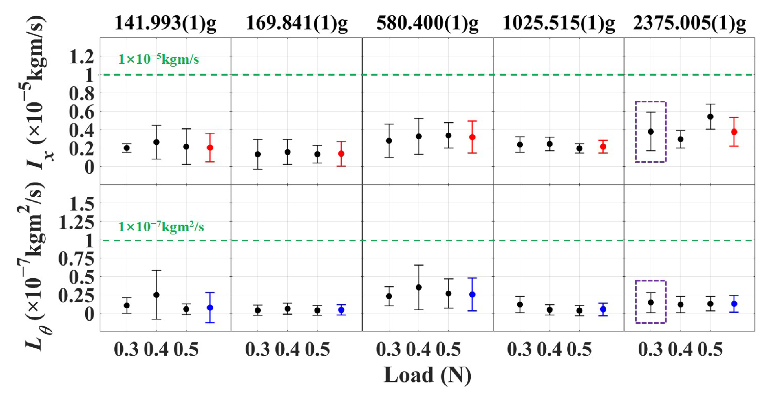
| 2375.005(1) g | 0.3–0.5 N | |||
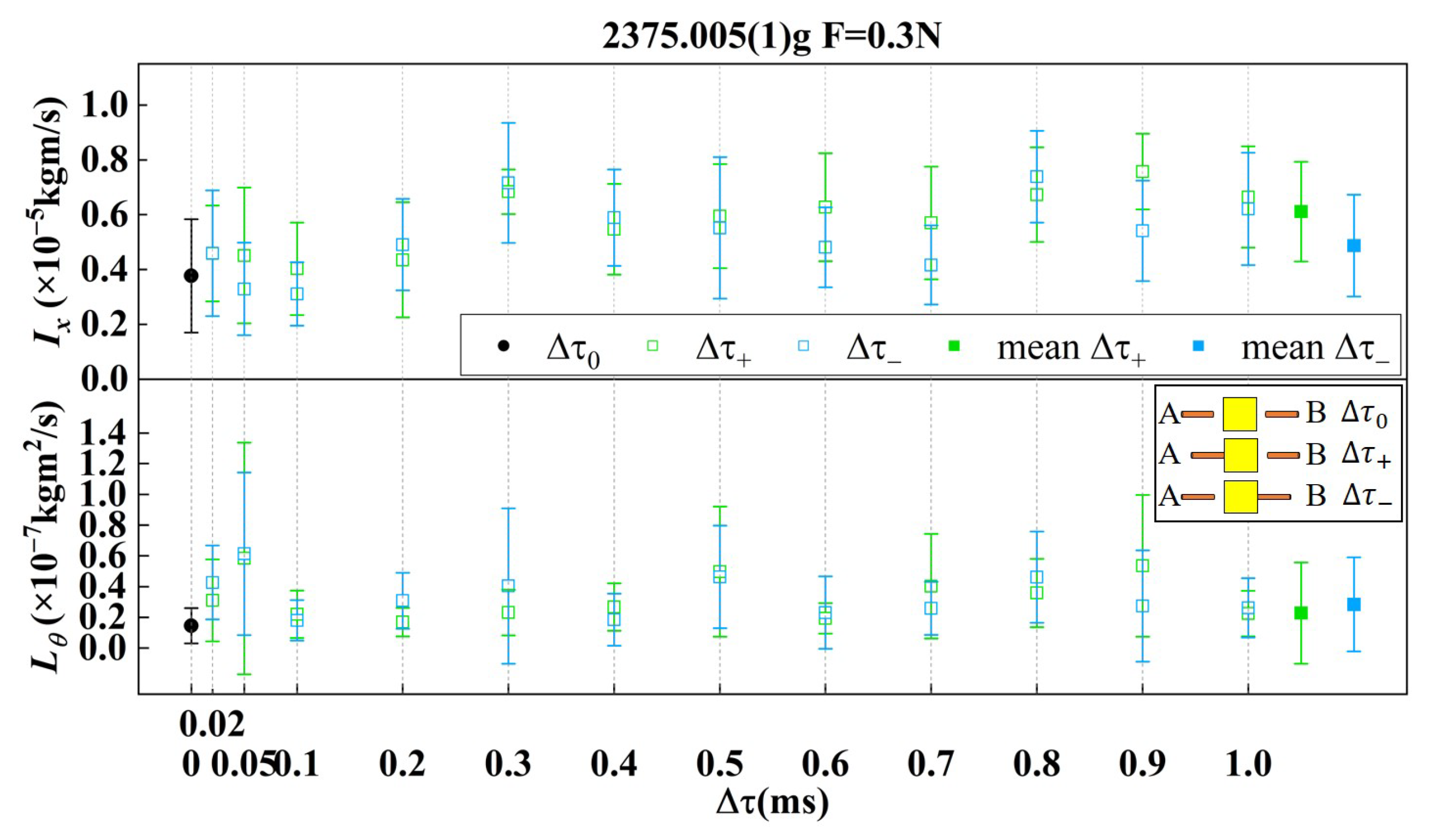
| 2375.005(1) g | 0.3 N | |||
| 2375.005(1) g | 0.3 N |
Disclaimer/Publisher’s Note: The statements, opinions and data contained in all publications are solely those of the individual author(s) and contributor(s) and not of MDPI and/or the editor(s). MDPI and/or the editor(s) disclaim responsibility for any injury to people or property resulting from any ideas, methods, instructions or products referred to in the content. |
© 2025 by the authors. Licensee MDPI, Basel, Switzerland. This article is an open access article distributed under the terms and conditions of the Creative Commons Attribution (CC BY) license (https://creativecommons.org/licenses/by/4.0/).
Share and Cite
Wang, J.; Shi, D.; Xue, C.; Yang, B.; Cai, B.; Chang, J.; Zhou, Z.; Tan, W.; Yang, S. On-Ground Testing of Dual-Sided Release Mechanism of TianQin Test Mass Using a Pendulum. Sensors 2025, 25, 2878. https://doi.org/10.3390/s25092878
Wang J, Shi D, Xue C, Yang B, Cai B, Chang J, Zhou Z, Tan W, Yang S. On-Ground Testing of Dual-Sided Release Mechanism of TianQin Test Mass Using a Pendulum. Sensors. 2025; 25(9):2878. https://doi.org/10.3390/s25092878
Chicago/Turabian StyleWang, Ji, Diwen Shi, Chao Xue, Biao Yang, Bingwei Cai, Jie Chang, Zefan Zhou, Wenhai Tan, and Shanqing Yang. 2025. "On-Ground Testing of Dual-Sided Release Mechanism of TianQin Test Mass Using a Pendulum" Sensors 25, no. 9: 2878. https://doi.org/10.3390/s25092878
APA StyleWang, J., Shi, D., Xue, C., Yang, B., Cai, B., Chang, J., Zhou, Z., Tan, W., & Yang, S. (2025). On-Ground Testing of Dual-Sided Release Mechanism of TianQin Test Mass Using a Pendulum. Sensors, 25(9), 2878. https://doi.org/10.3390/s25092878