
Parameter Identification of Permanent Magnet Synchronous Motor Based on LSOSMO Algorithm


Abstract
1. Introduction
2. Mathematical Model of PMSMs
3. The Design of Improved SMO Algorithm
3.1. The Principle of SMO Algorithm
3.1.1. Population Initialization
3.1.2. Local Leader Phase (LLP)
3.1.3. Global Leader Phase (GLP)
3.1.4. Global Leader Learning (GLL) Phase
3.1.5. Local Leader Learning (LLL) Phase
3.1.6. Local Leader Decision (LLD) Phase
3.1.7. Global Leader Decision (GLD) Phase
3.2. The Design of LSOSMO
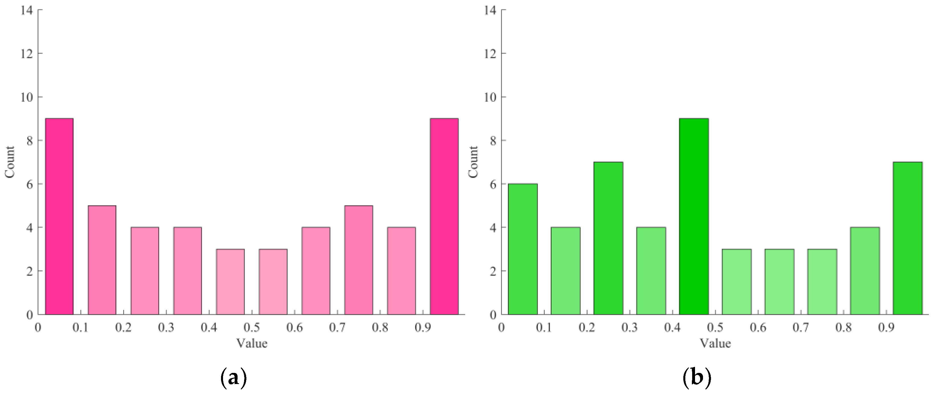
3.2.1. Logistic–Sine Chaotic Mapping Strategy
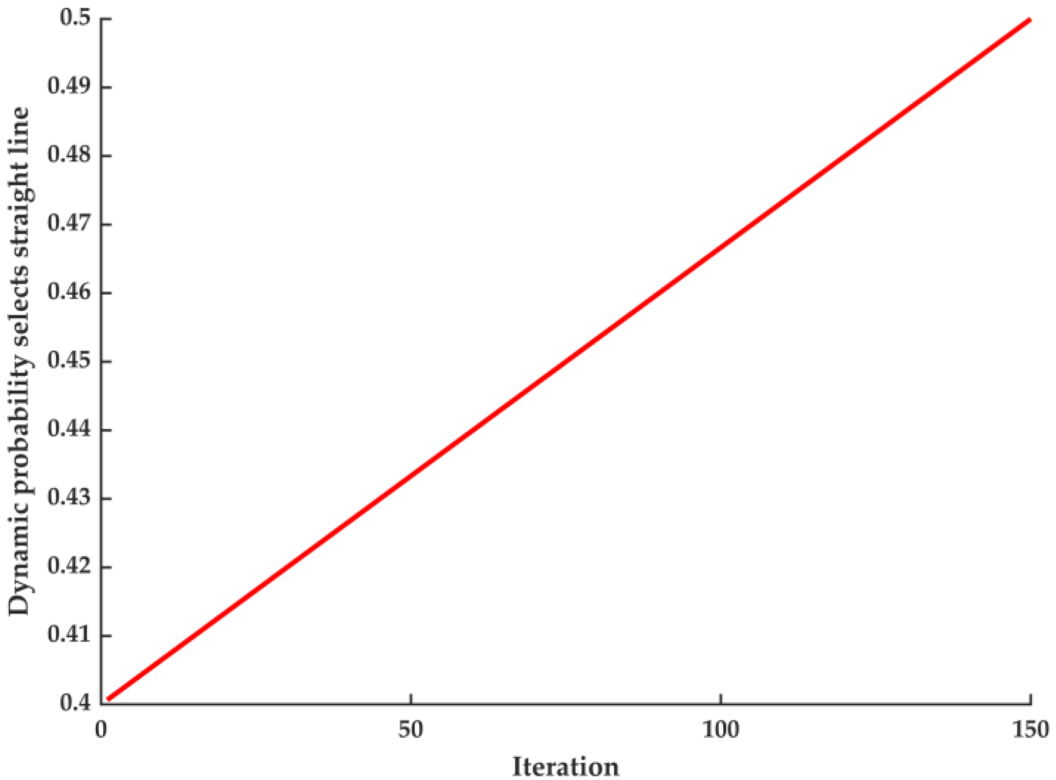
3.2.2. The Strategy of Dynamic Probability Adaptive T-Distribution
3.2.3. The Strategy of Opposition-Based Learning
4. PMSM Parameter Identification Based on LSOSMO
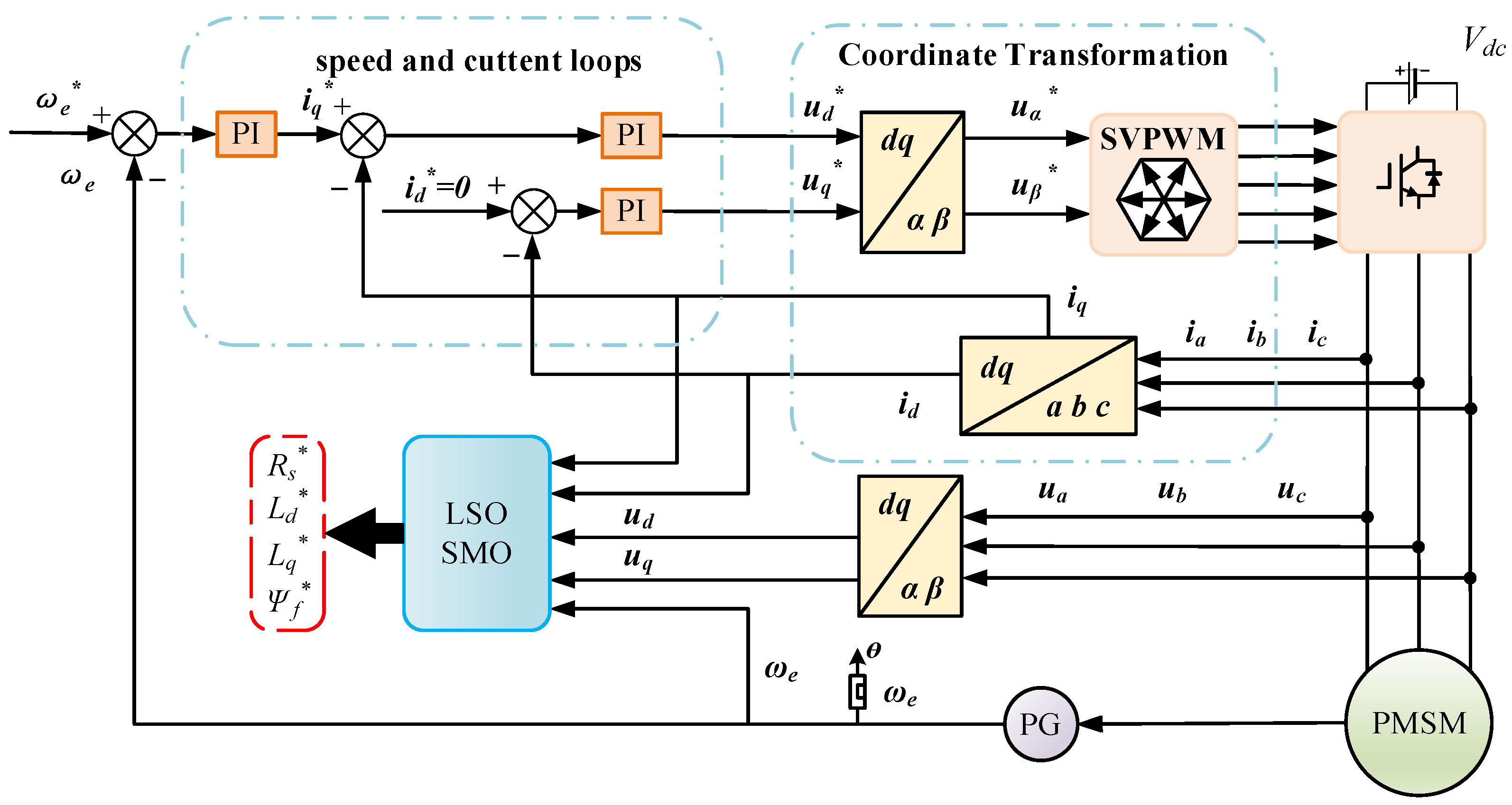
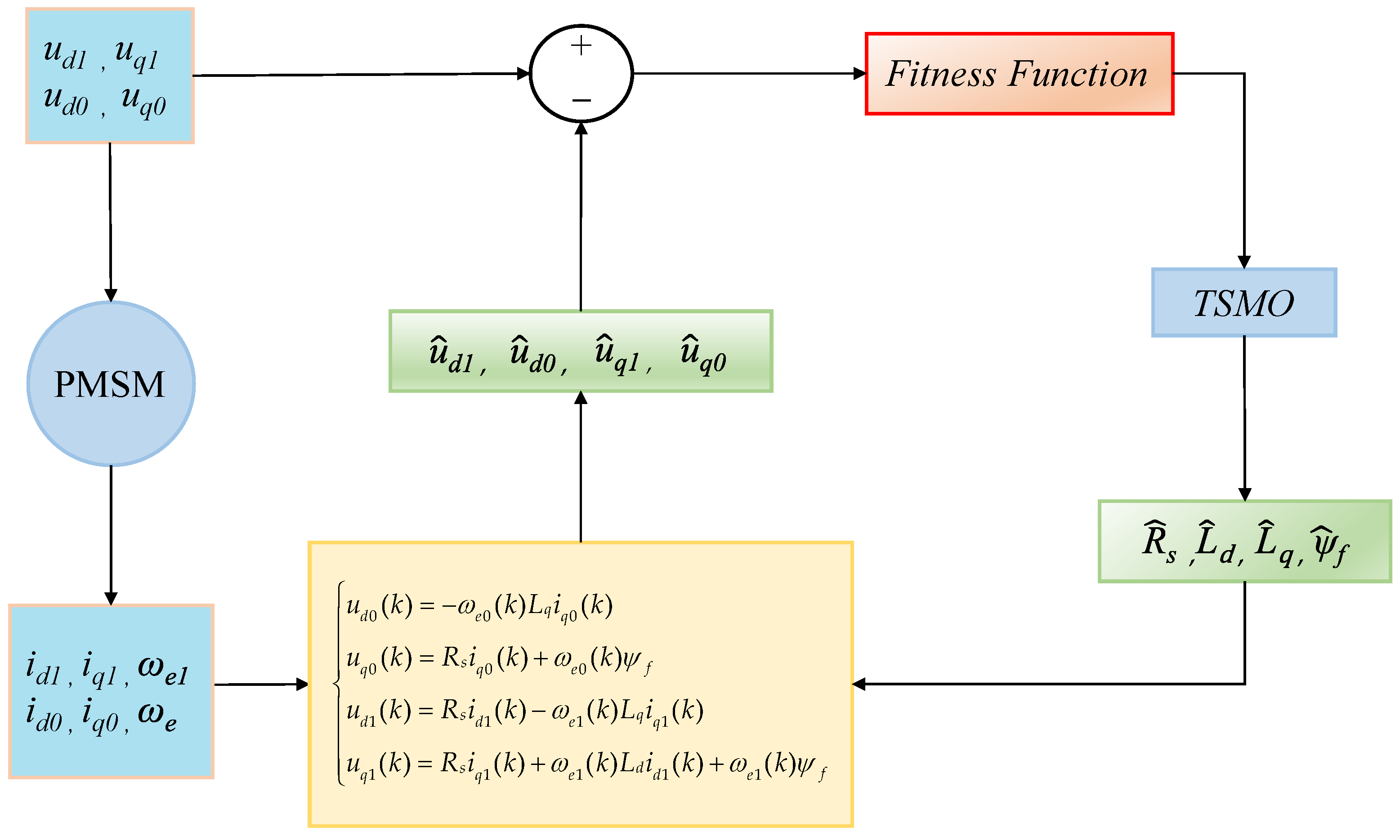
4.1. Parameter Identification Principle of PMSMs
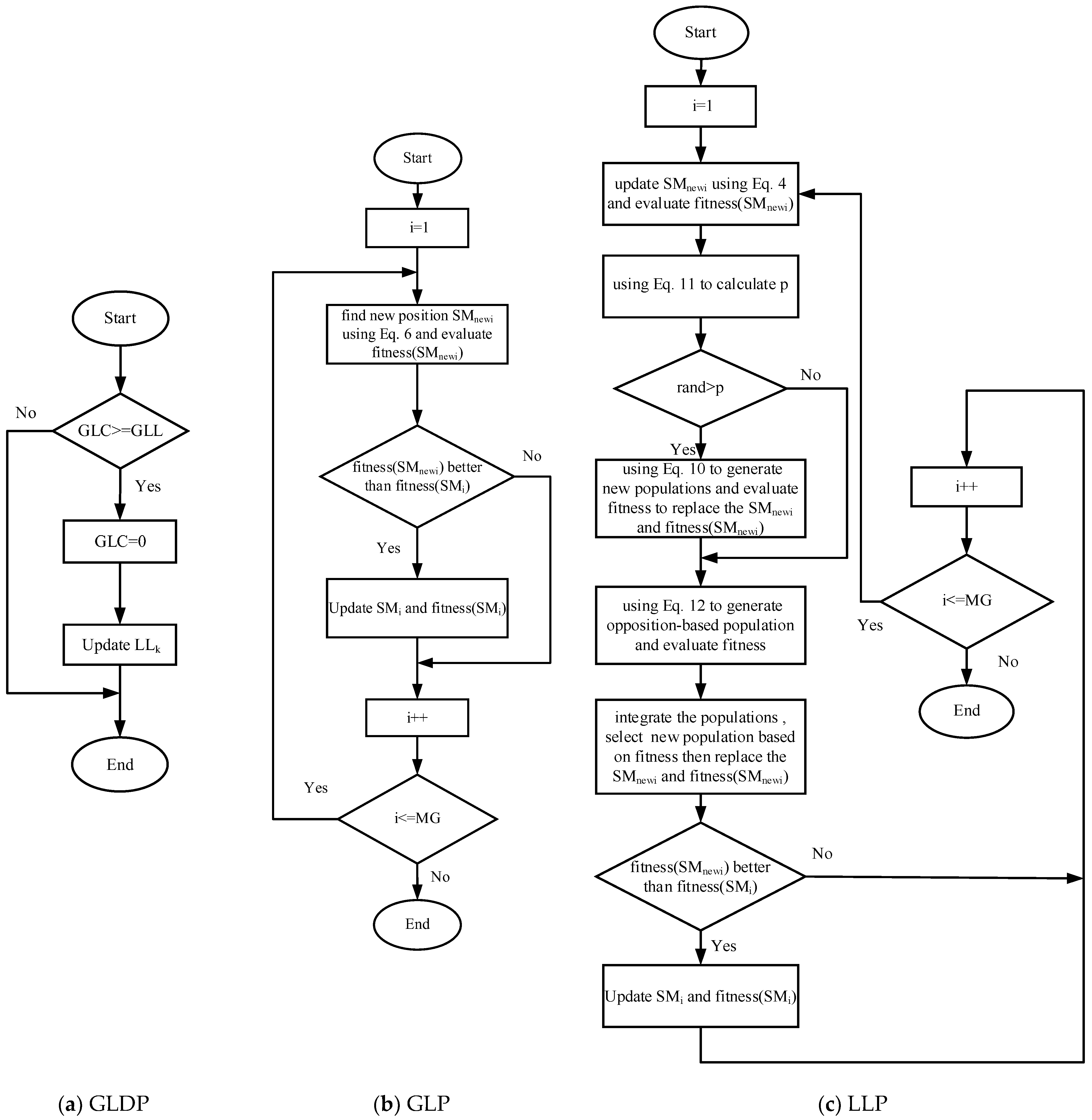
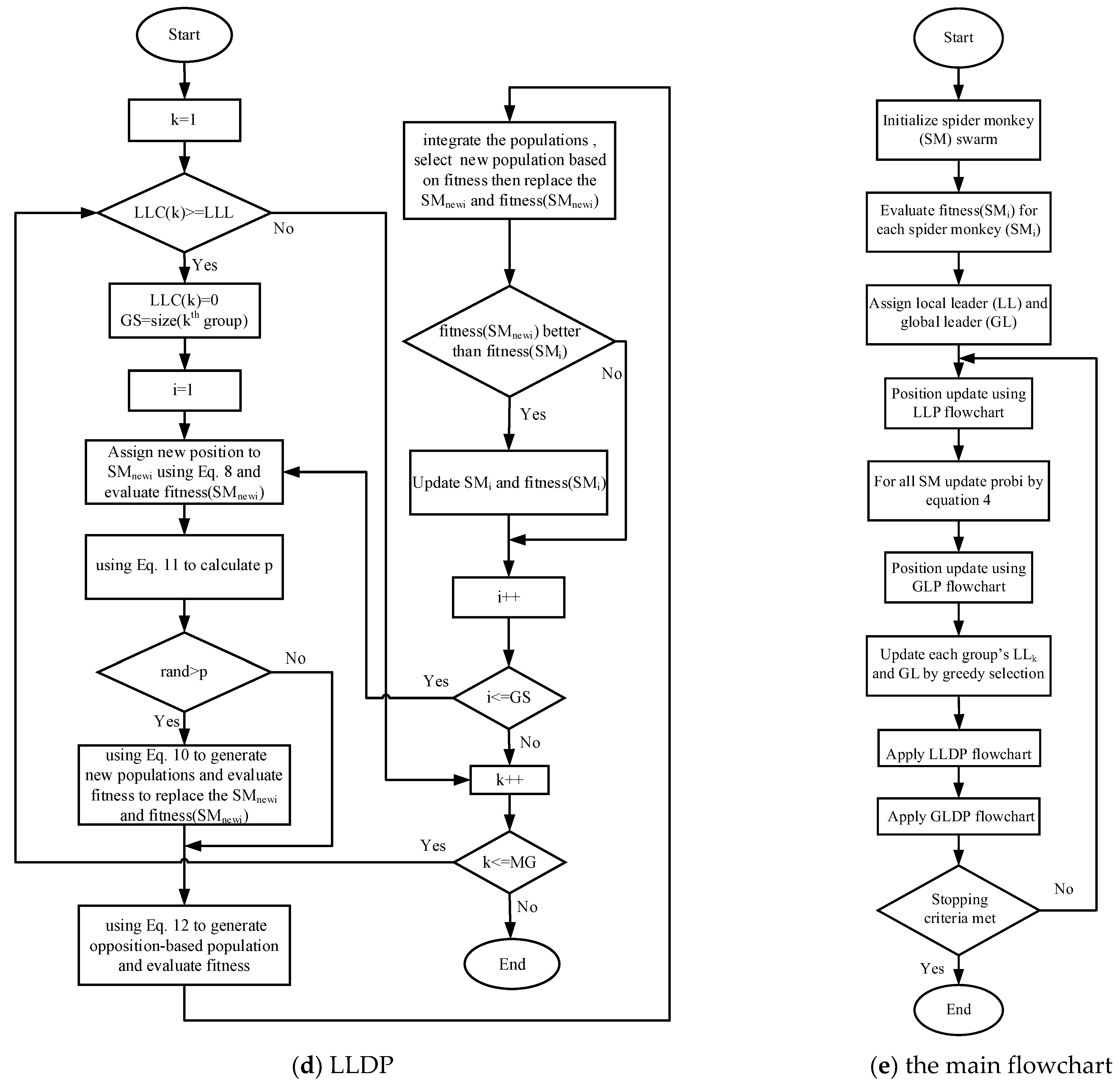
4.2. The Flowchart of the LSOSMO in PMSM Parameter Identification
- Utilize Equation (9) to generate the initial population, and establish the parameters: Local Leader Limit, Global Leader Limit, and pr, etc. First bullet;
- Compute the fitness value for each SM by Equation (13).
- The greedy selection method is employed to determine the positions of LLP and GLP.
- If the termination condition is not satisfied, execute the following steps: Second bullet;
- By Equation (5), a new position is generated, and the optimal solution is identified.
- The dynamic probability p in Equation (11) determines whether to implement the adaptive t-distribution strategy.
- The opposition-based learning strategy described in Equation (12) is employed to generate the opposition-based learning population.
- Calculate the fitness value of each individual in the population according to Equation (13) and select the individual with the smallest fitness value as the optimal individual.
- The selection probability of all group members is calculated according to Equation (7).
- Use Equation (6) to update the positions of all team members selected by probability .
- Execute steps 1 through 6 to update the local leader position, while the global leader position is updated using the greedy selection strategy.
- If the local leader position does not update its position within a specified number of times, the group member is redirected to foraging through the local leader decision phase. Generate a new population according to Equation (8) and perform steps 2 to 4 to replace the original population.
- If the global leader position does not update its position within the specified number of iterations, and the number of subgroups does not reach the maximum groups (MG), the subgroup is divided into smaller groups; otherwise, all groups are merged. First item;
- Figure 6 illustrates the flowcharts of the LSOSMO.
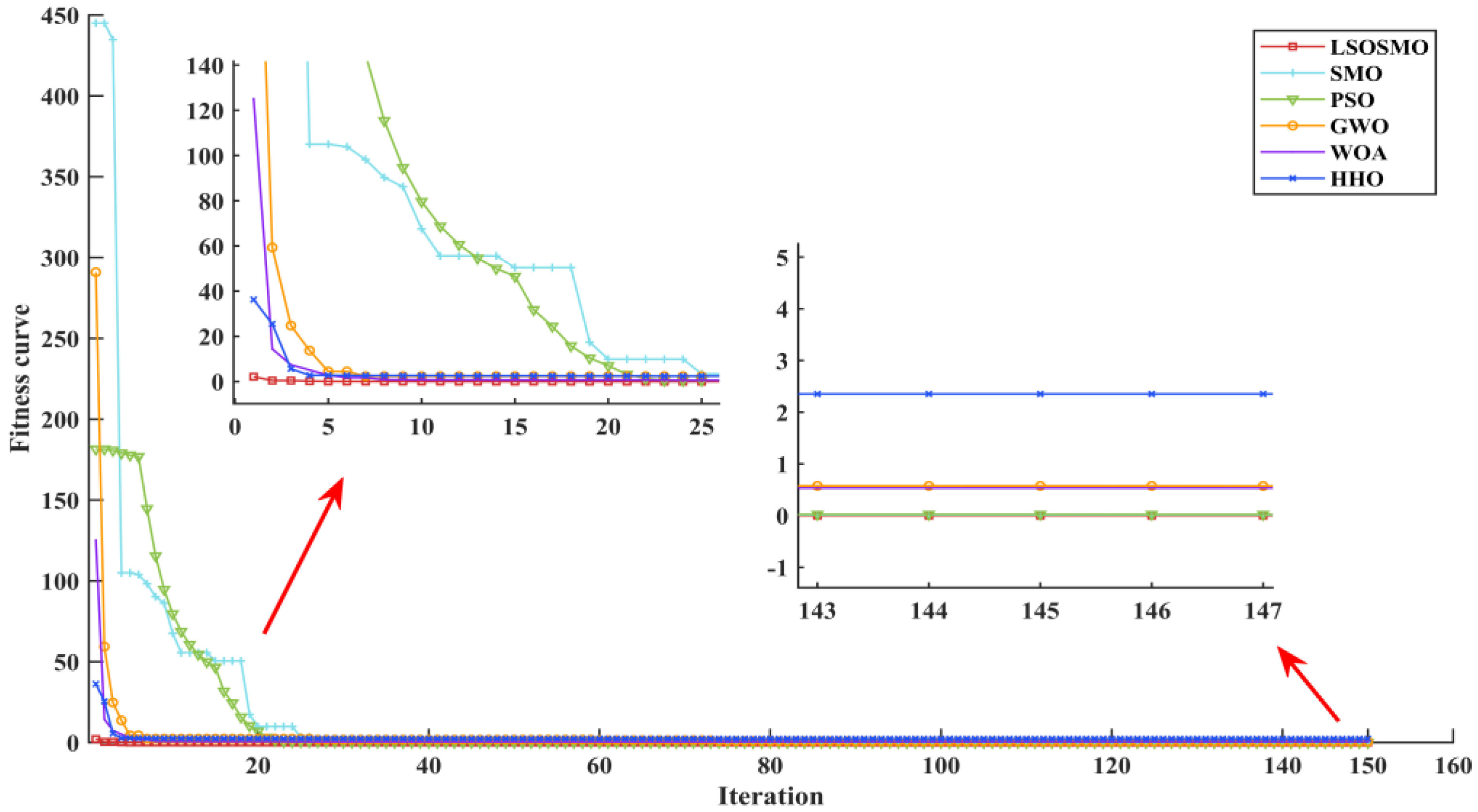
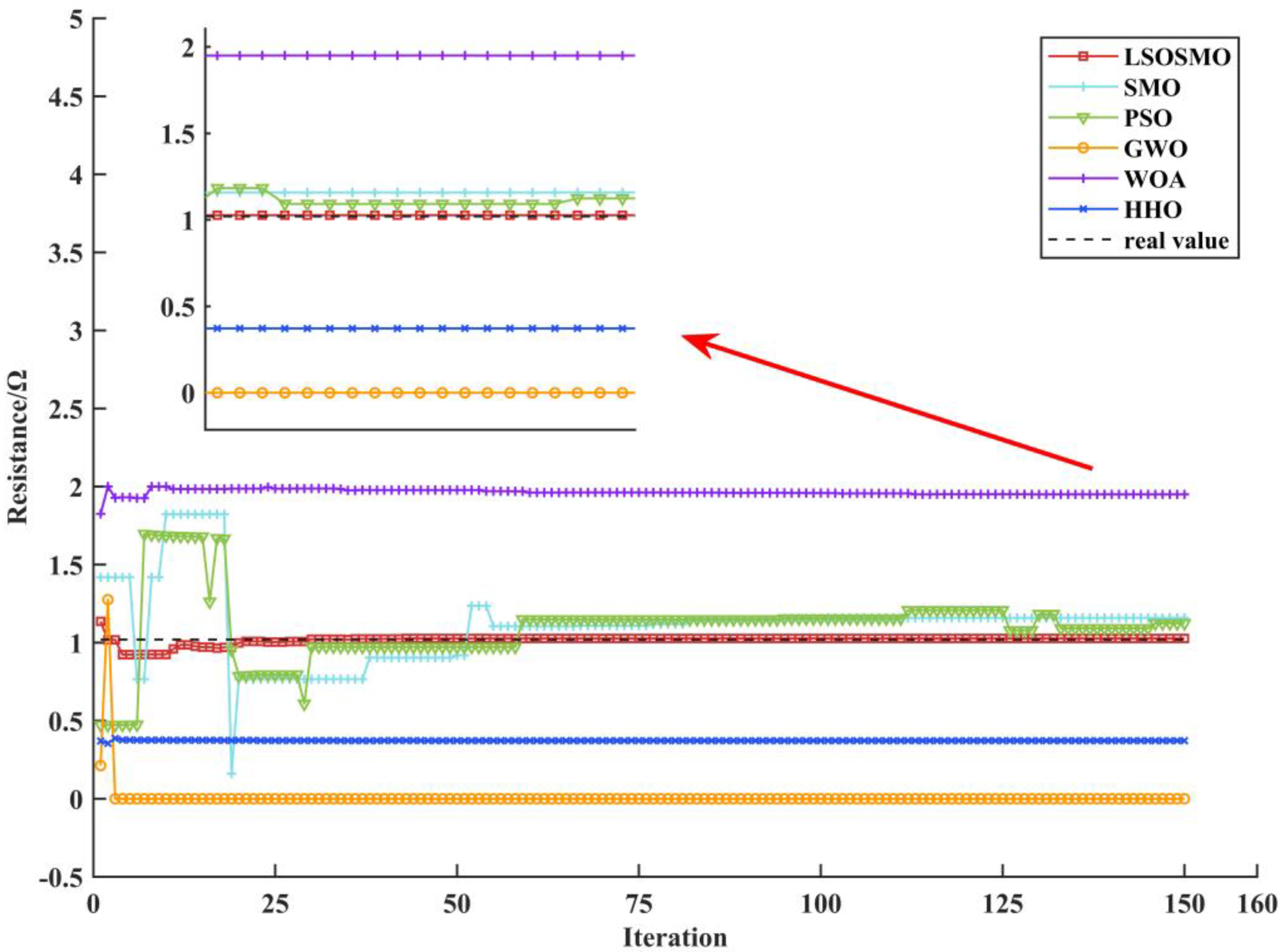
5. Simulation Verification and Analysis
6. Conclusions
Author Contributions
Funding
Institutional Review Board Statement
Informed Consent Statement
Data Availability Statement
Acknowledgments
Conflicts of Interest
References
- Brescia, E.; Massenio, P.R.; Nardo, M.D.; Cascella, G.L.; Gerada, C.; Cupertino, F. Nonintrusive Parameter Identification of IoT-Embedded Isotropic PMSM Drives. IEEE J. Emerg. Sel. Top. Power Electron. 2023, 11, 5195–5207. [Google Scholar] [CrossRef]
- Wang, H.; Fan, M.; Xiao, Y.; Yang, Y.; Dai, Z.; Zhang, X.; Rodriguez, J. Four Consecutive Samples Based Sensorless Control for PMSM Drives. IEEE Trans. Transp. Electrif. 2024, 10, 2082–2094. [Google Scholar] [CrossRef]
- Tian, M.; Wang, B.; Yu, Y.; Dong, Q.; Xu, D. Adaptive Active Disturbance Rejection Control for Uncertain Current Ripples Suppression of PMSM Drives. IEEE Trans. Ind. Electron. 2024, 71, 2320–2331. [Google Scholar] [CrossRef]
- Dong, X.; Mao, J.; Yan, Y.; Zhang, C.; Yang, J. Generalized Dynamic Predictive Control for Nonlinear Systems Subject to Mismatched Disturbances With Application to PMSM Drives. IEEE Trans. Ind. Electron. 2024, 71, 954–964. [Google Scholar] [CrossRef]
- Rafaq, M.S.; Midgley, W.; Steffen, T. A Review of the State of the Art of Torque Ripple Minimization Techniques for s. IEEE Trans. Ind. Inform. 2024, 20, 1019–1031. [Google Scholar] [CrossRef]
- Feng, W.; Zhang, W.; Huang, S. A Novel Parameter Estimation Method for PMSM by Using Chaotic Particle Swarm Optimization With Dynamic Self-Optimization. IEEE Trans. Veh. Technol. 2023, 72, 8424–8432. [Google Scholar] [CrossRef]
- Su, G.; Wang, P.; Guo, Y.; Cheng, G.; Wang, S.; Zhao, D. Multiparameter Identification of Permanent Magnet Synchronous Motor Based on Model Reference Adaptive System—Simulated Annealing Particle Swarm Optimization Algorithm. Electronics 2022, 11, 159. [Google Scholar] [CrossRef]
- Ahandani, M.A.; Abbasfam, J.; Kharrati, H. Parameter Identification of Permanent Magnet Synchronous Motors Using Quasi-Opposition-Based Particle Swarm Optimization and Hybrid Chaotic Particle Swarm Optimization Algorithms. Appl. Intell. 2022, 52, 13082–13096. [Google Scholar] [CrossRef]
- Zhang, Y.; Bi, Y.; Wang, S. Parameter Identification of Permanent Magnet Synchronous Motor Based on Extended Kalman Filter and Gradient Correction. In Proceedings of the 2020 IEEE International Conference on Mechatronics and Automation (ICMA), Beijing, China, 13–16 October 2020; pp. 718–722. [Google Scholar]
- Gan, H.; Cao, Z.; Chen, P.; Luo, Y.; Luo, X. Fractional-Order Electromagnetic Modeling and Identification for PMSM Servo System. ISA Trans. 2024, 147, 527–539. [Google Scholar] [CrossRef]
- Mi, M.; Che, Y.; Li, H.; Zhao, S. Identification of Rotor Position of Permanent Magnet Spherical Motor Based on Compressed Sensing. IEEE Trans. Ind. Inform. 2023, 19, 9157–9164. [Google Scholar] [CrossRef]
- Zhou, Y.; Yang, X. Analytical Method to Calculate Inductances of Spoke-Type Permanent-Magnet Synchronous Motors with Damping Bars. IEEE Trans. Ind. Electron. 2023, 70, 8254–8263. [Google Scholar] [CrossRef]
- Wang, Q.; Liu, S.; Zhang, G.; Ding, D.; Li, B.; Wang, G.; Xu, D. Zero-Sequence Voltage Error Elimination-Based Offline VSI Nonlinearity Identification for PMSM Drives. IEEE Trans. Transp. Electrif. 2024, 10, 55–66. [Google Scholar] [CrossRef]
- Lian, C.; Xiao, F.; Liu, J.; Gao, S. Parameter and VSI Nonlinearity Hybrid Estimation for PMSM Drives Based on Recursive Least Square. IEEE Trans. Transp. Electrif. 2023, 9, 2195–2206. [Google Scholar] [CrossRef]
- Wang, K.; Yan, Y.; Mao, K.; Zheng, S.; Hao, M.; Zhang, Y. Adaptive Current Decoupling Control Scheme Based on Online Multi-Parameter Identification for High-Speed Permanent Magnet Synchronous Motor in Fuel Cell. Int. J. Hydrogen Energy 2024, 86, 542–553. [Google Scholar] [CrossRef]
- Brosch, A.; Wallscheid, O.; Boecker, J. Long-Term Memory Recursive Least Squares Online Identification of Highly Utilized Permanent Magnet Synchronous Motors for Finite-Control-Set Model Predictive Control. IEEE Trans. Power Electron. 2023, 38, 1451–1467. [Google Scholar] [CrossRef]
- Yang, G.; Weizhang, S.; Wheeler, P.; Yang, Y. An Apparent Inductance Online Identification for Sensorless Control of Permanent Magnet Synchronous Motor. Electron. Lett. 2024, 60, e13233. [Google Scholar] [CrossRef]
- Song, W.; Zou, Y.; Ma, C.; Zhang, S. Digital Twin Modeling Method of Three-Phase Inverter-Driven PMSM Systems for Parameter Estimation. IEEE Trans. Power Electron. 2024, 39, 2360–2371. [Google Scholar] [CrossRef]
- Chen, P.; Ma, R.; Song, S.; Chen, Z. Sensorless Capability Expansion for SPMSM Based on Inductance Parameter Identification. Energies 2024, 17, 3219. [Google Scholar] [CrossRef]
- Lu, G.; Su, J.; Yang, G.; Liu, F. Offline Parameter Self-Learning Method for Low-Impedance Dual Three-Phase PMSMs: Addressing AC Losses and Inverter Nonlinearity. IEEE J. Emerg. Sel. Top. Power Electron. 2024, 12, 2730–2743. [Google Scholar] [CrossRef]
- Liu, S.; Wang, Q.; Wang, G.; Li, B.; Ding, D.; Zhang, G.; Xu, D. Virtual-Axis Injection Based Online Parameter Identification of PMSM Considering Cross Coupling and Saturation Effects. IEEE Trans. Power Electron. 2023, 38, 5791–5802. [Google Scholar] [CrossRef]
- Guan, R.; Liu, J.; Li, M.; Xiao, M.; Shi, X. A Compensation Method for PMSM Sensorless Control with Parameter Identification Considering SMO Observation Error. IET Electr. Power Appl. 2024, 18, 1730–1739. [Google Scholar] [CrossRef]
- Liu, S.; Wang, Q.; Zhang, G.; Wang, G.; Xu, D. Online Temperature Identification Strategy for Position Sensorless PMSM Drives With Position Error Adaptive Compensation. IEEE Trans. Power Electron. 2022, 37, 8502–8512. [Google Scholar] [CrossRef]
- Wang, L.; Zhang, S.; Zhang, C.; Zhou, Y. An Improved Deadbeat Predictive Current Control Based on Parameter Identification for PMSM. IEEE Trans. Transp. Electrif. 2024, 10, 2740–2753. [Google Scholar] [CrossRef]
- Liu, Z.; Shen, B.; Kong, W.; Fan, X.; Peng, K.; Qu, R. Analytical Approach for Position Observation Error Correction in IPMSM Sensorless Drives Using Online Multiparameter Estimation. IEEE Trans. Power Electron. 2024, 39, 9230–9243. [Google Scholar] [CrossRef]
- Shi, S.; Guo, L.; Chang, Z.; Zhao, C.; Chen, P. Current Controller Based on Active Disturbance Rejection Control With Parameter Identification for PMSM Servo Systems. IEEE Access 2023, 11, 46882–46891. [Google Scholar] [CrossRef]
- Xiao, Q.; Liao, K.; Shi, C.; Zhang, Y. Parameter Identification of Direct-Drive Permanent Magnet Synchronous Generator Based on EDMPSO-EKF. IET Renew. Power Gener. 2022, 16, 1073–1086. [Google Scholar] [CrossRef]
- Darani, A.Y.; Mirzaeian Dehkordi, B. Sensorless Control of a Surface-Mounted PMSM by an Improved Flux Observer with RLS Parameter Identification Method. Proceedings of the 2023 14th Power Electronics, Drive Systems, and Technologies Conference (PEDSTC), Babol, Iran, 31 January–2 February 2023, IEEE: Babol, Iran, 2023; 1–7. [Google Scholar]
- Yu, H.; Wang, J.; Xin, Z. Model Predictive Control for PMSM Based on Discrete Space Vector Modulation with RLS Parameter Identification. Energies 2022, 15, 4041. [Google Scholar] [CrossRef]
- Zhou, S.; Wang, D.; Du, M.; Li, Y.; Cao, S. Double Update Intelligent Strategy for Permanent Magnet Synchronous Motor Parameter Identification. CMC-Comput. Mater. Contin. 2023, 74, 3391–3404. [Google Scholar] [CrossRef]
- Zhou, S.; Wang, D.; Li, Y. Parameter Identification of Permanent Magnet Synchronous Motor Based on Modified- Fuzzy Particle Swarm Optimization. Energy Rep. 2023, 9, 873–879. [Google Scholar] [CrossRef]
- Li, H.; Jian, X. Parameter Identification of Permanent Magnet Synchronous Motor Based on CGCRAO Algorithm. IEEE Access 2023, 11, 124319–124330. [Google Scholar] [CrossRef]
- Wu, Z.; Du, C. The Parameter Identification of PMSM Based on Improved Cuckoo Algorithm. Neural Process. Lett. 2019, 50, 2701–2715. [Google Scholar] [CrossRef]
- Wang, Z.; Yang, M.; Gao, L.; Wang, Z.; Zhang, G.; Wang, H.; Gu, X. Deadbeat Predictive Current Control of Permanent Magnet Synchronous Motor Based on Variable Step-Size Adaline Neural Network Parameter Identification. IET Electr. Power Appl. 2020, 14, 2007–2015. [Google Scholar] [CrossRef]
- Ke, X.; Zhang, J.; Jian, W.; Peng, G.; Chen, Y. Multi-Parameter Identification of PMSM Based on IGWO Algorithm. In Advanced Manufacturing and Automation XI; Wang, Y., Martinsen, K., Yu, T., Wang, K., Eds.; Springer: Berlin/Heidelberg, Germany, 2022; pp. 547–555. [Google Scholar]
- Bansal, J.C.; Sharma, H.; Jadon, S.S.; Clerc, M. Spider Monkey Optimization Algorithm for Numerical Optimization. Memetic Comput. 2014, 6, 31–47. [Google Scholar] [CrossRef]
- Xia, Y.; He, X. Flower pollination alogtithm fusing chaotic mapping and multiplication-division operators and applications. Intell. Comput. Appl. 2024, 14, 76–84. [Google Scholar]
- Zhang, W.; Liu, S. Improved sparrow search algorithm based on adaptive t-distribution and golden sine and its application. Microelectron. Comput. 2022, 39, 17–24. [Google Scholar] [CrossRef]
- Wang, Z.; Chai, J.; Xiang, X.; Sun, X.; Lu, H. A Novel Online Parameter Identification Algorithm Designed for Deadbeat Current Control of the Permanent-Magnet Synchronous Motor. IEEE Trans. Ind. Appl. 2022, 58, 2029–2041. [Google Scholar] [CrossRef]
- Mirjalili, S.; Mirjalili, S.M.; Lewis, A. Grey Wolf Optimizer. Adv. Eng. Softw. 2014, 69, 46–61. [Google Scholar] [CrossRef]
- Mirjalili, S.; Lewis, A. The Whale Optimization Algorithm. Adv. Eng. Softw. 2016, 95, 51–67. [Google Scholar] [CrossRef]
- Heidari, A.A.; Mirjalili, S.; Faris, H.; Aljarah, I.; Mafarja, M.; Chen, H. Harris Hawks Optimization: Algorithm and Applications. Future Gener. Comput. Syst. 2019, 97, 849–872. [Google Scholar] [CrossRef]


| Parameter | Value |
|---|---|
| /Ω | 1.02 |
| /H | 0.0055 |
| /H | 0.012 |
| /Wb | 0.1824 |
| /(kg·mg2) | 0.003 |
| /(N·m·s) | 0.008 |
| Polar logarithm Pn | 3 |
| T(N/m) | 5 |
| Algorithm | Parameter Settings |
|---|---|
| LSOSMO | pr = 0.1; ; ; ; pop = 50; N = 150; MG = 5; |
| SMO | pr = 0.1; pop = 50; N = 150; MG = 5; |
| PSO | c1 = 0.8; c2 = 1; ; ; pop = 50; N = 150; |
| GWO | pop = 50; N = 150; |
| WOA | pop = 50; N = 150; |
| HHO | pop = 50; N = 150; |
| Parameter | Value | LSOSMO | SMO | PSO | GWO | WOA | HHO |
|---|---|---|---|---|---|---|---|
| value | 1.0269 | 1.0301 | 0.9071 | 0.7615 | 0.8138 | 0.9074 | |
| error (%) | 0.6754 | 0.9904 | 11.0718 | 25.3474 | 20.2115 | 11.0430 | |
| std | 0.7401 × 10⁻⁴ | 0.8471 × 10⁻⁴ | 0.1992 | 0.4423 | 0.4661 | 0.4506 | |
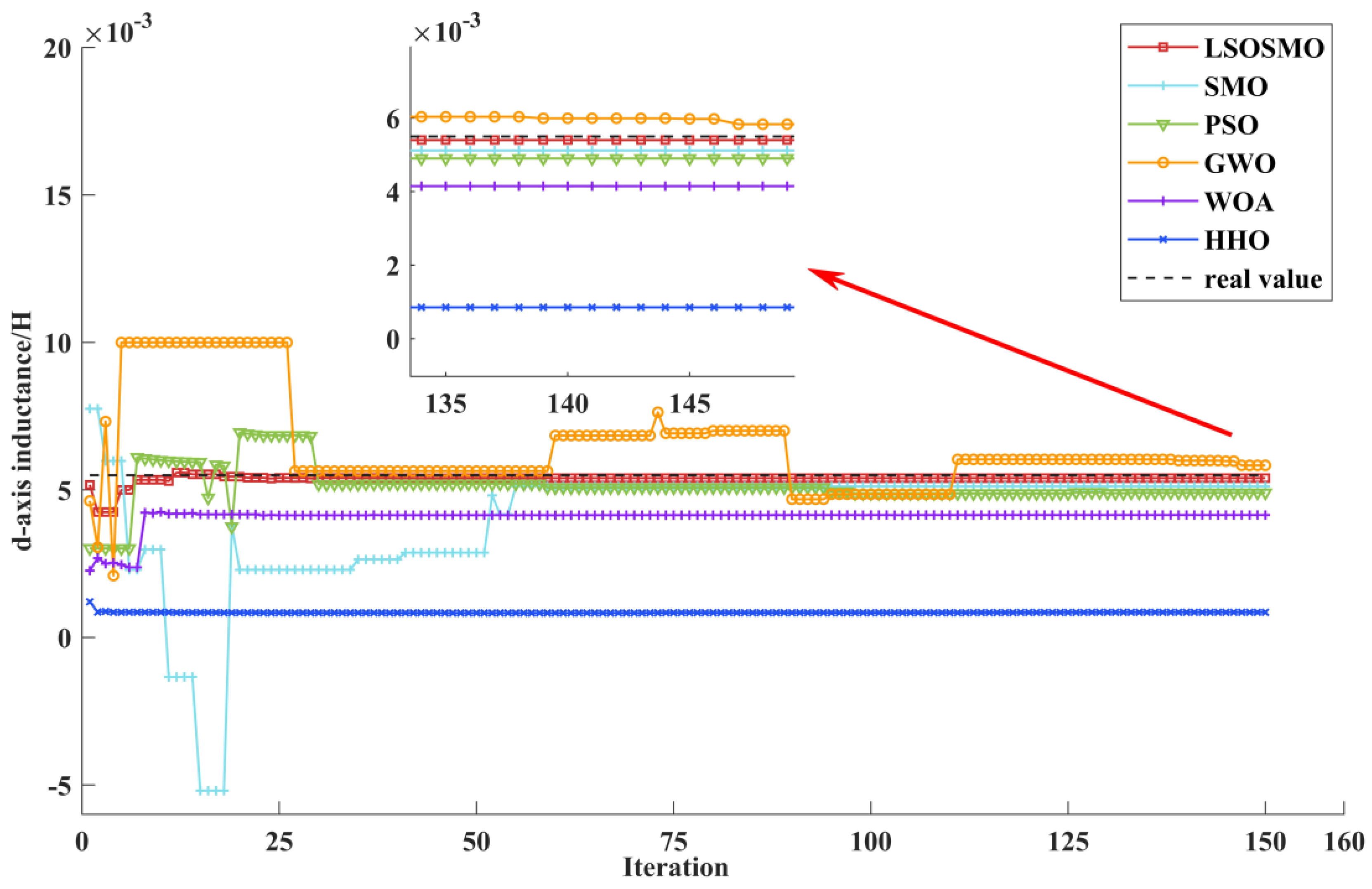
| value | 0.0054 | 0.0054 | 0.0053 | 0.0053 | 0.0047 | 0.0047 | |
| error (%) | 1.0851 | 2.1535 | 3.0015 | 3.2281 | 14.6840 | 14.4618 | |
| std | 0.0014 × 10⁻⁴ | 0.0014 × 10⁻⁴ | 0.0006 | 0.0010 | 0.0018 | 0.0018 | |
| value | 0.0120 | 0.0120 | 0.0121 | 0.0121 | 0.0121 | 0.0120 | |
| error (%) | 0.0811 | 0.1069 | 0.4248 | 0.9104 | 0.6559 | 0.3945 | |
| std | 0.0004 × 10⁻⁴ | 0.0005 × 10⁻⁴ | 0.0001 | 0.0002 | 0.0002 | 0.0002 | |
| value | 0.1824 | 0.1823 | 0.1839 | 0.1856 | 0.1843 | 0.1832 | |
| error (%) | 0.1563 | 0.1984 | 0.6584 | 1.5863 | 0.8947 | 0.2608 | |
| std | 0.0100 × 10⁻⁴ | 0.0105 × 10⁻⁴ | 0.0025 | 0.0059 | 0.0053 | 0.0057 |
Disclaimer/Publisher’s Note: The statements, opinions and data contained in all publications are solely those of the individual author(s) and contributor(s) and not of MDPI and/or the editor(s). MDPI and/or the editor(s) disclaim responsibility for any injury to people or property resulting from any ideas, methods, instructions or products referred to in the content. |
© 2025 by the authors. Licensee MDPI, Basel, Switzerland. This article is an open access article distributed under the terms and conditions of the Creative Commons Attribution (CC BY) license (https://creativecommons.org/licenses/by/4.0/).
Share and Cite
Zhang, S.; Zhou, Z.; Pu, Y.; Li, Y.; Xu, Y. Parameter Identification of Permanent Magnet Synchronous Motor Based on LSOSMO Algorithm. Sensors 2025, 25, 2648. https://doi.org/10.3390/s25092648
Zhang S, Zhou Z, Pu Y, Li Y, Xu Y. Parameter Identification of Permanent Magnet Synchronous Motor Based on LSOSMO Algorithm. Sensors. 2025; 25(9):2648. https://doi.org/10.3390/s25092648
Chicago/Turabian StyleZhang, Songcan, Zhuangzhuang Zhou, Yi Pu, Yan Li, and Yingxi Xu. 2025. "Parameter Identification of Permanent Magnet Synchronous Motor Based on LSOSMO Algorithm" Sensors 25, no. 9: 2648. https://doi.org/10.3390/s25092648
APA StyleZhang, S., Zhou, Z., Pu, Y., Li, Y., & Xu, Y. (2025). Parameter Identification of Permanent Magnet Synchronous Motor Based on LSOSMO Algorithm. Sensors, 25(9), 2648. https://doi.org/10.3390/s25092648