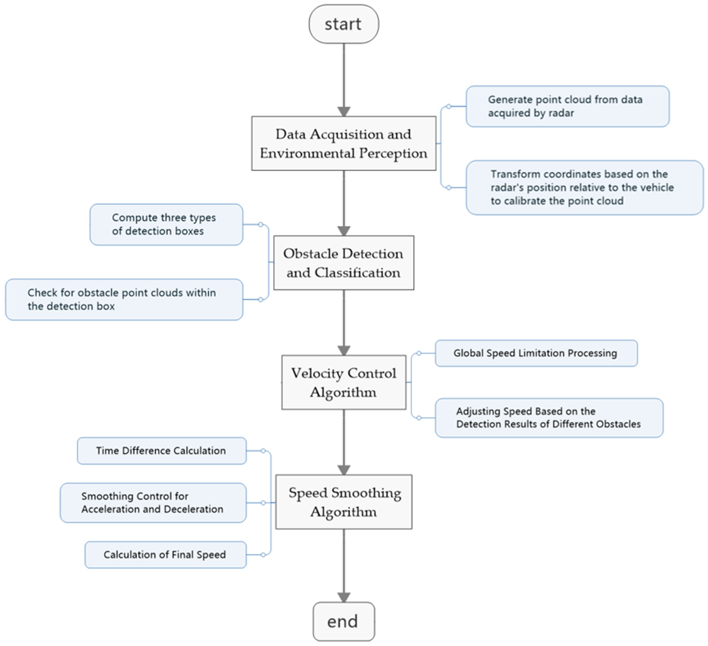
2.2.2. Obstacle Detection and Classification
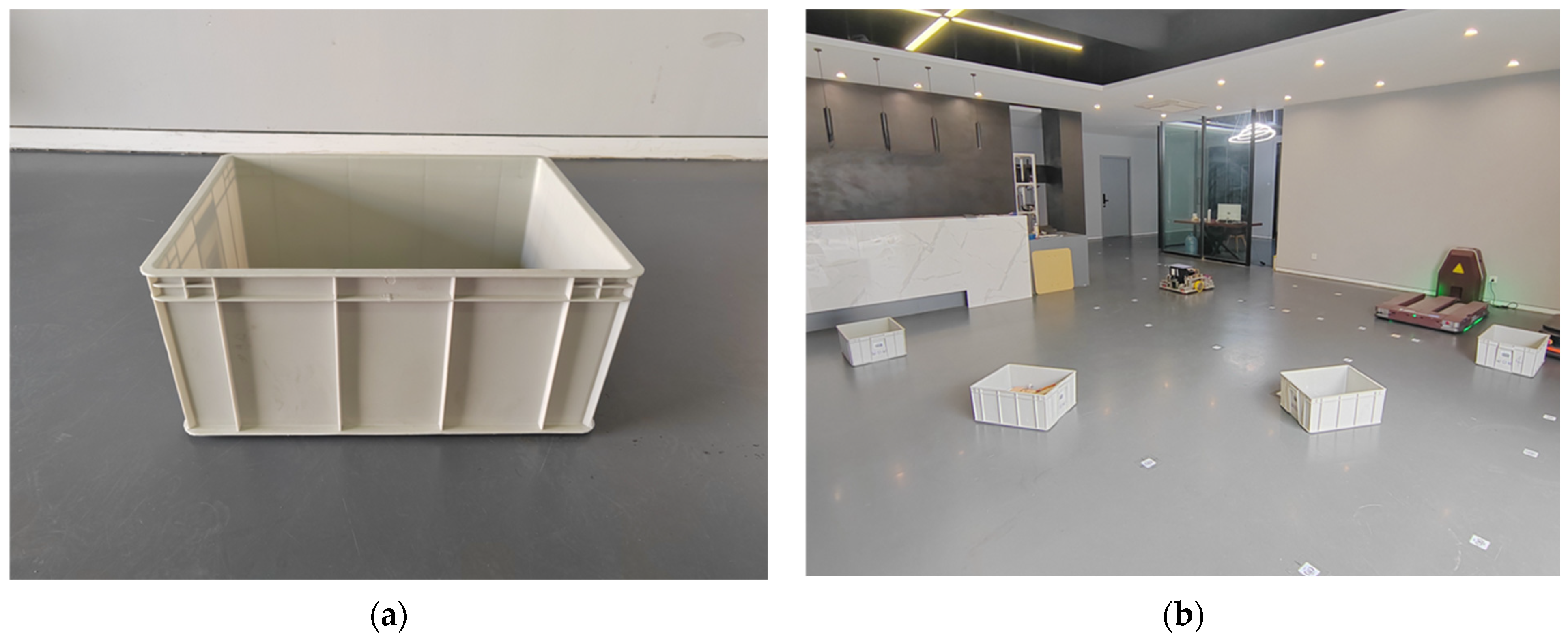
To effectively detect obstacles and implement appropriate avoidance measures, the AEB algorithm first utilizes point cloud data acquired from sensors such as LiDAR and depth cameras to construct a series of rectangular detection boxes. These detection boxes are used to predict the AGV’s future positions over different time steps and serve as the basis for subsequent obstacle avoidance decisions. By accurately computing these detection boxes, the algorithm can simulate the potential relative position changes between the AGV and obstacles in the environment during motion.
The detection region’s bounding box is classified into three state types: , , and , with the priority decreasing in the same order. indicates that the obstacle is too close, requiring the AGV to stop immediately; indicates that the obstacle is relatively close, prompting the AGV to gradually reduce its speed until it comes to a halt; and indicates that the obstacle is at a safe distance, allowing the AGV to decelerate according to the set parameters. When the obstacle’s point cloud enters the corresponding detection box, the system will adopt the appropriate obstacle avoidance strategy based on the current state.
The generation of the detection box follows the steps below:
The AGV chassis is approximated as a rectangle, with its vertices represented by two-dimensional coordinates
. The bounding box is generated based on the physical outline of the AGV (i.e., the planar area occupied by the AGV). The outline vertices are typically defined with the AGV’s center as the origin. The formula is as follows:
In the code, these vertices are passed as parameters and stored in a list.
- 2.
Calculate the detection box.
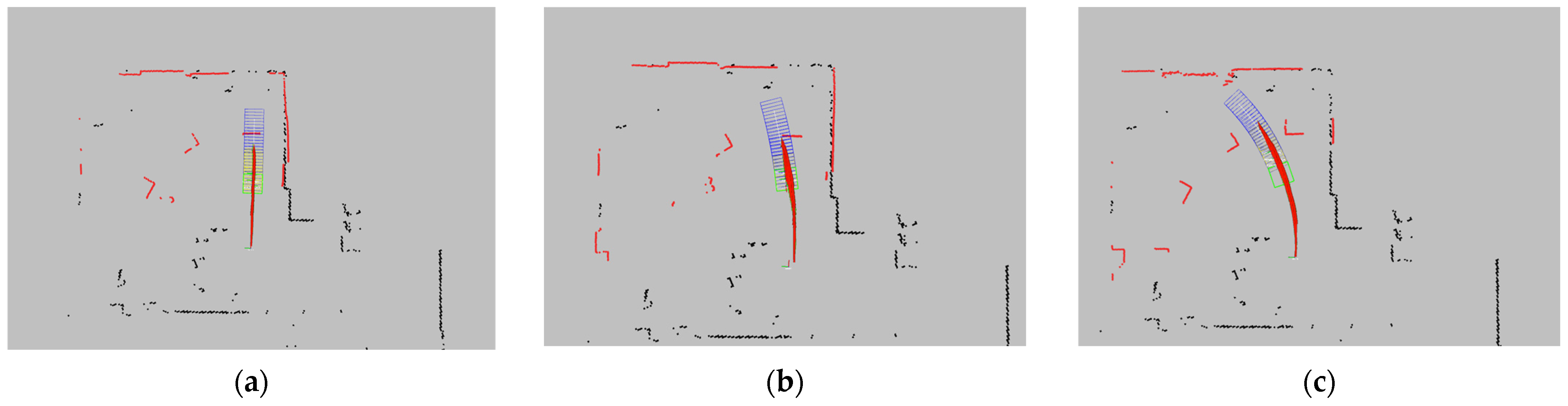
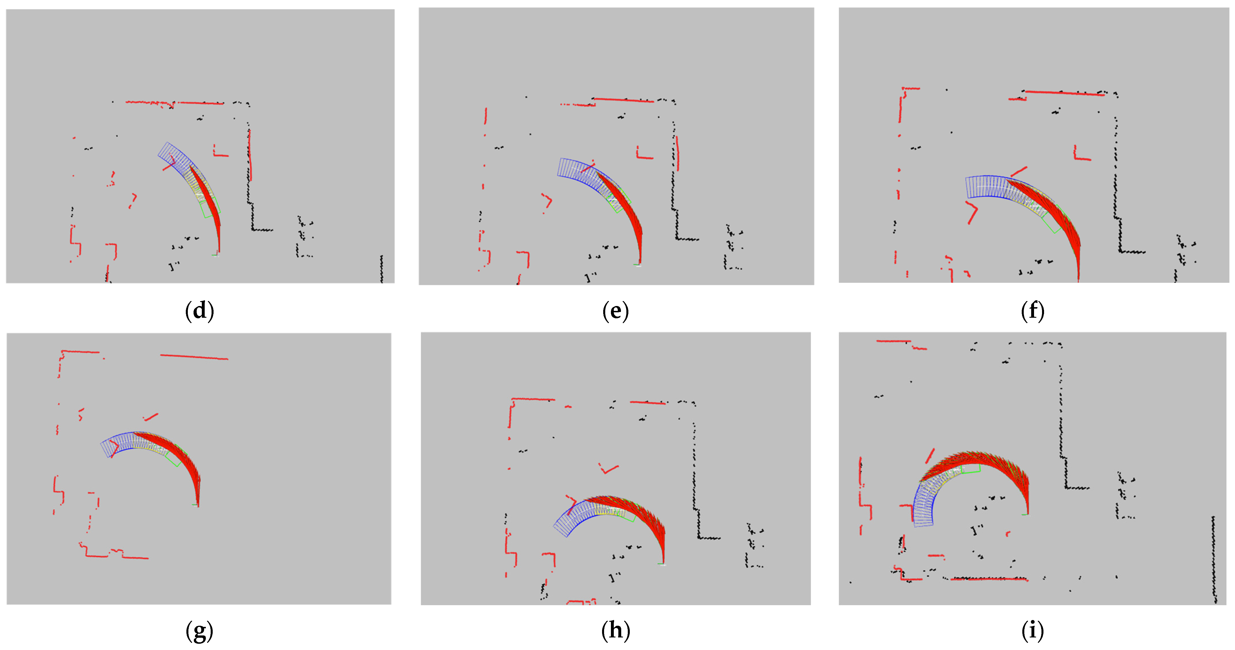
The AEB algorithm generates a bounding box for obstacle detection and avoidance decision-making using real-time velocity information from sensors and predefined parameters. The shape and size of the bounding box are determined by the AGV’s physical outline and its current pose, with the four vertex coordinates calculated based on the AGV’s physical dimensions and current position. The algorithm continuously updates these bounding boxes to reflect the AGV’s motion trajectory and the surrounding environment in real-time, enabling proactive collision risk assessment and response.
The emergency stop bounding box (corresponding to the
state detection box) is a rectangle defined by four vertices with the AGV’s center as the origin. The dimensions of this rectangle are slightly larger than the AGV’s physical dimensions. The generation formula is as follows:
In the code, these vertices are passed as parameters and stored in a list.
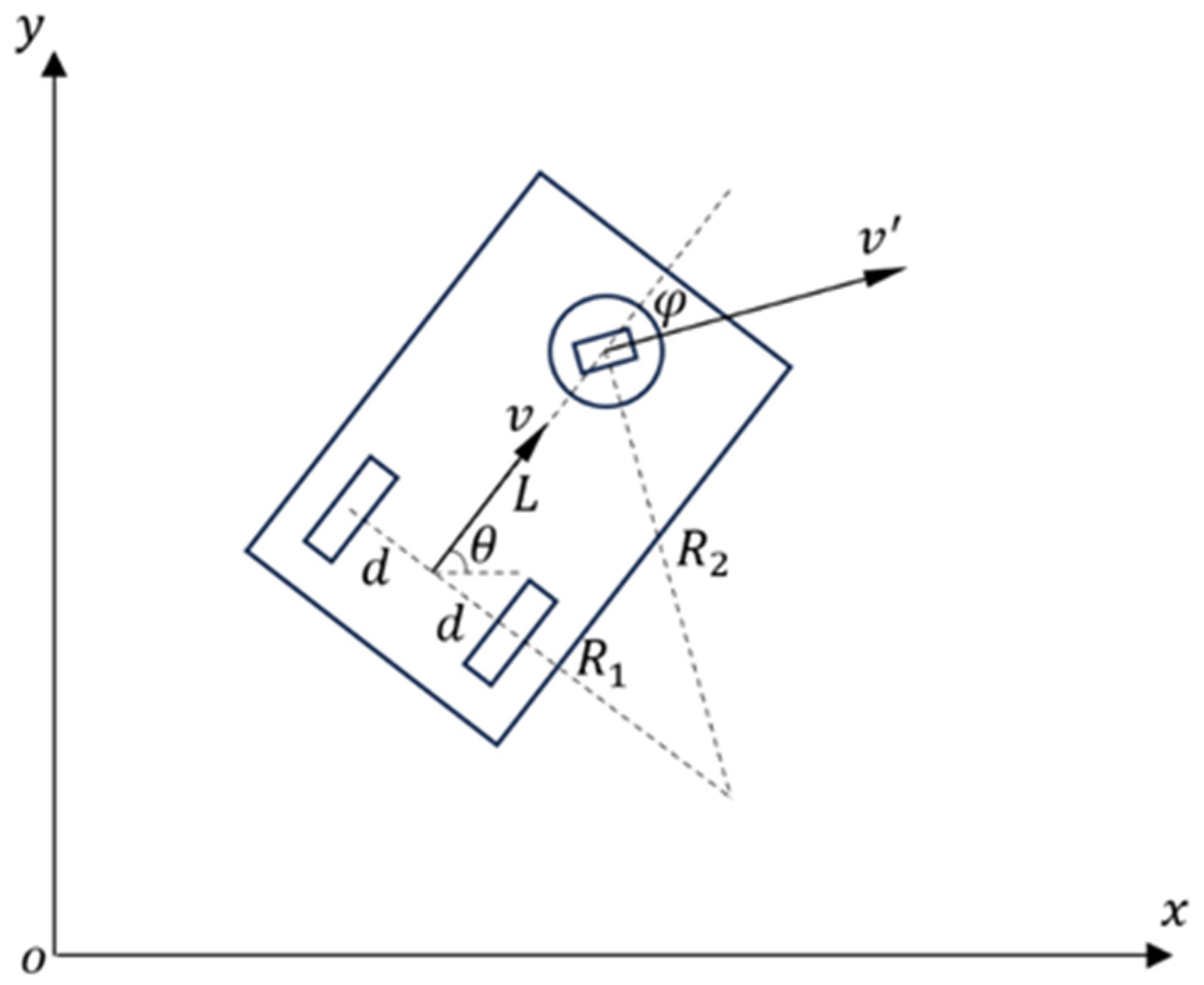
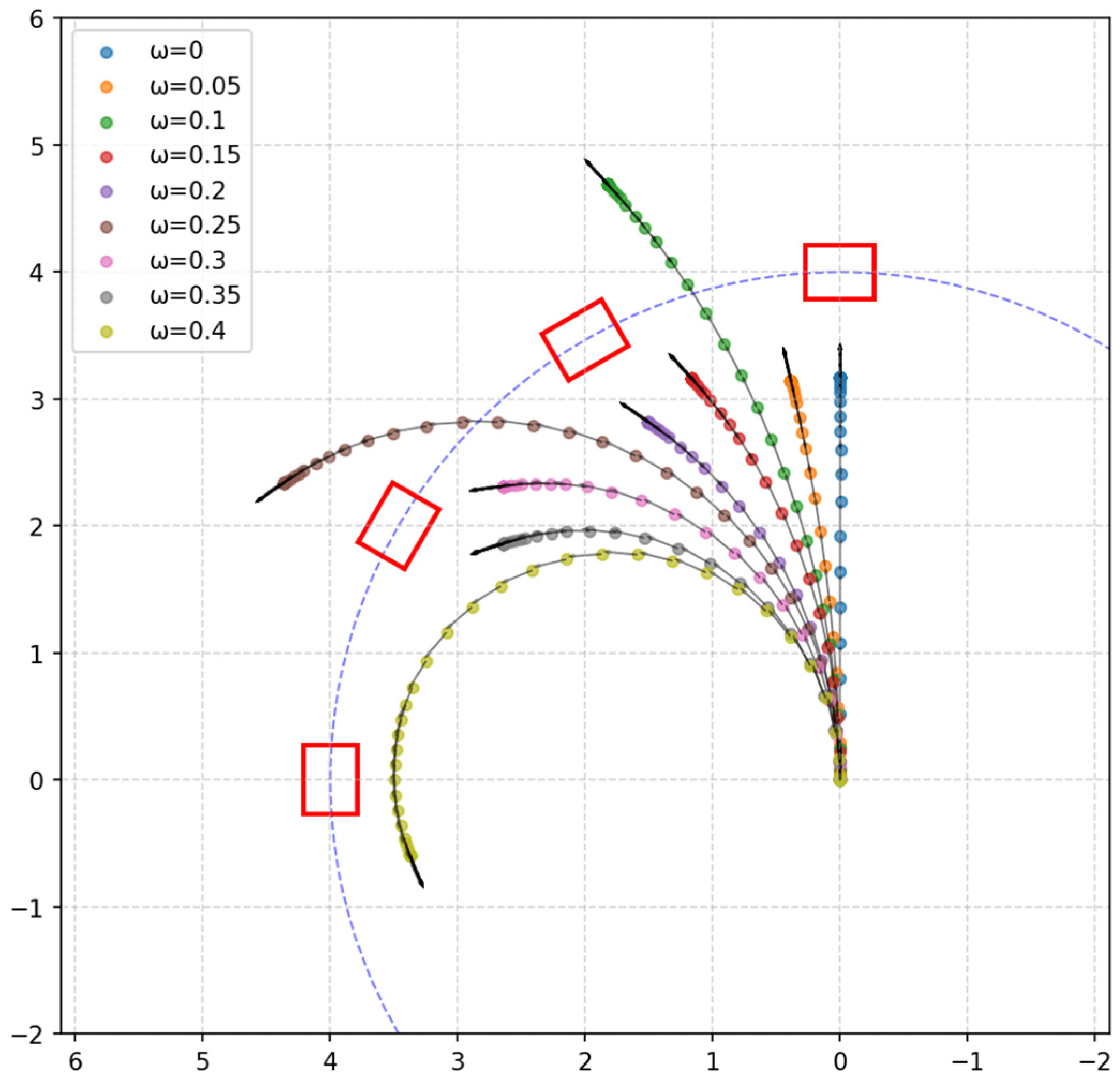
The speed stop bounding box (corresponding to the state detection box) is primarily generated based on the linear velocity feedback from the AGV’s sensors. The algorithm predicts the positions and quaternions (collectively referred to as the pose) of a series of future time points in the global coordinate system, starting from the AGV’s current coordinate system, based on the existing linear velocity. Then, using the coordinates of the AGV’s outline vertices in the local AGV coordinate system and the previously calculated pose, the algorithm computes the coordinates of the bounding box vertices corresponding to the AGV’s position at future time points in the current AGV coordinate system. With these vertex coordinates, the corresponding rectangle is then determined. The detailed steps are as follows:
First, calculate the minimum stopping distance
required for the AGV to come to a stop from its current linear velocity. The formula is as follows:
where
is the real-time linear velocity feedback from the AGV’s motor encoder, calculated as the square root of the sum of squares of the linear velocities in the x and y directions,
and
.
is the maximum deceleration set for the AGV. For safety reasons,
is generally smaller than the AGV’s maximum achievable deceleration. The calculation of
is used to define the range of the speed stop bounding box. If an obstacle enters these boxes, then the AGV must immediately stop with maximum deceleration to ensure safety.
Next, the number of detection boxes
is calculated. The formula is as follows:
where
is the distance interval between the centers of adjacent detection boxes, which is set as a parameter before the program runs. The result of the formula may yield a remainder. If a remainder exists, then the result is incremented by 1, and the distance between the centers of the last and second-to-last boxes is adjusted to equal the remainder. The calculation of
is used to determine the total number of detection boxes, which will be used for stepwise iterative counting in the subsequent process.
After calculating , the algorithm will compute the pose of all detection boxes, with the calculation method being as follows:
First, we calculate the small time difference
between adjacent detection boxes, using the following formula:
Next, a loop is initiated to iterate over the calculated values, with the number of iterations equal to .
The algorithm calculates the angular displacement
of the AGV within the time interval
, based on the angular velocity
of the current AGV coordinate axes:
where
is the real-time angular velocity feedback from the AGV’s motor encoder.
The encoder feedback velocities
and
are transformed based on the rotation matrix of the respective coordinate system. The calculation formula is as follows:
represents the linear velocity vector in the detection box coordinate system (assuming that the AGV’s linear velocity remains constant).
represents the transformation between the detection box coordinate system and the AGV’s current coordinate system.
is the rotation angle corresponding to each detection box, initially set to and incremented by in each iteration of the loop.
represents the linear velocity vector in the AGV’s current coordinate system, transformed from the detection box coordinate system.
Next, the position of the detection box’s coordinate system origin is calculated based on the obtained velocity, using the following formula:
Based on , the angular orientation of the detection box coordinate system is obtained, and it is represented in quaternion form along with the previously calculated vector to fully represent the pose of the detection box coordinate system. After iterations, the final pose data are stored in an array containing multiple pose objects, where each pose object represents the position and orientation of the AGV at a specific moment.
After calculating the pose of the detection box coordinate system, the algorithm calculates and publishes the coordinates of each detection box’s rectangular vertices in the AGV’s current coordinate system.
The algorithm first retrieves the four vertices of the detection box in the detection box coordinate system by reading the AGV’s outline vertices (footprint), with the vertices represented as follows:
Then, the pose transformation matrix is used to convert the representation of these four vertices in the detection box coordinate system into their representation in the AGV’s current coordinate system. The formula is as follows:
represents the vertices of the detection box in the detection box coordinate system.
represents the pose transformation between the detection box coordinate system and the AGV’s current coordinate system.
is the rotation angle corresponding to each detection box.
and are the coordinates of the detection box’s coordinate system origin in the AGV’s current coordinate system.
represents the linear velocity vector in the detection box coordinate system, expressed in the AGV’s current coordinate system.
is the index of the vertex coordinates, which can take any value from the set .
After the four sets of coordinates are calculated, they are stored in the array and then published.
Simultaneously to the generation of the speed stop bounding boxes, the deceleration bounding box (corresponding to the
state detection box) is also generated following the same set of rules. After generating these deceleration bounding boxes, the algorithm will generate additional deceleration bounding boxes according to the same rules. The formula for calculating the number of additional deceleration bounding boxes is as follows:
is the additional detection distance added to the previous speed stop bounding boxes, and it is set as a parameter before the program runs. Since the data undergo iteration during the calculation of pose transformation for the bounding boxes, the data used to generate the additional deceleration bounding boxes are based on the speed stop bounding boxes. Therefore, must subtract the previously generated number of bounding boxes, .
This formula generates rectangular boxes within the specified detection range, ensuring that the minimum number of bounding boxes generated is .
- 3.
Determining Whether an Obstacle is Inside the Bounding Box.
Obstacle detection is performed by analyzing the geometric relationship between the point cloud data and the detection box. The core algorithm used is the ray-casting method. In this method, a ray is cast from the point in any arbitrary direction, and the number of intersections between the ray and the boundaries of the rectangular bounding box is calculated. If the ray intersects the boundary of the bounding box an odd number of times, then the point is considered to be inside the bounding box; if the number of intersections is even, then the point is considered to be outside the bounding box.
The algorithm casts a horizontal ray (i.e., along the
x-axis direction) from the obstacle point
to the right. To determine whether the point is inside the bounding box, we need to check whether the ray intersects with any of the four edges of the rectangular bounding box. Each edge of the bounding box can be represented as a line segment, defined as follows:
The algorithm first iterates through the four edges, denoting the coordinates of the two points on each edge as
and
. If
, then it is assumed that there is no intersection between the obstacle point and this edge. If
or
, then it is also assumed that there is no intersection between the obstacle point and this edge. When neither of the above two conditions hold, the x-coordinate of the intersection point between the edge and the ray can be calculated using the following formula:
where
is the x-coordinate of the intersection point. If
, then it is determined that there is an intersection.
2.2.3. Velocity Control Algorithm
First, the velocity feedback from the AGV encoder will be processed to ensure that it does not exceed the system’s maximum speed limit. Let the feedback velocity command be represented as
, where
is the linear velocity of the AGV in the
x-axis direction,
is the linear velocity in the
y-axis direction, and
is the angular velocity during AGV turning. The algorithm will process the input velocity based on the maximum speed limit
to obtain the processed velocity command:
where
,
, and
are the system-defined maximum linear velocities along the
x-axis and
y-axis components and the maximum angular velocity, respectively.
- 2.
Adjusting Speed Based on the Detection Results of Different Obstacles.
Since the velocity used in the following calculations is a composite of the components in the x and y directions, a conversion is required. The steps are as follows:
Using the Pythagorean theorem, the original linear velocities in the x and y directions are combined, as expressed by the following equation:
where
and
are the linear velocity components of the AGV in the
x-axis and
y-axis directions, respectively.
When an obstacle is detected in close proximity to the AGV, the system will immediately set the AGV’s speed to zero:
At this point, both the AGV’s linear velocity and angular velocity will be set to zero, and the AGV will come to an immediate stop. Meanwhile, the system will call to set the AEB status to emergency stop: . The current AEB status will then be published.
When an obstacle is detected and a collision with the AGV’s future position is imminent, requiring the AGV to stop, the system will perform a smooth deceleration based on the current speed and the distance between the AGV and the obstacle, ensuring collision avoidance while maintaining smooth motion. For safety reasons, after the speed reaches zero, regardless of any changes in the obstacle’s status, the algorithm will maintain this state for a few seconds, with the duration adjustable. After this delay, the algorithm will call and set it to the normal stop state: .
When the system detects an obstacle and deceleration is required, the AGV’s speed will be adjusted based on the distance to the obstacle and the current speed. The AGV will decelerate to the minimum safe speed. If the distance to the obstacle is
, then the AGV’s final speed
can be calculated using the following formula:
Here,
is a function used to adjust the target speed based on the distance to the obstacle. It is generally configured according to the specific requirements of the application. The core of the function consists of two lists (unit: meters).
The values in the two lists correspond to each other. When the distance between the AGV’s center and the specified predicted bounding box of the obstacle is less than the value of , the maximum speed will be reduced to the corresponding value in . The values and the number of elements in the lists can be flexibly adjusted based on actual requirements. However, based on safety considerations and practical use, the following constraints apply:
The obstacle distance
and the speed
must be in increasing order, and the speed corresponding to the obstacle must be less than the limit speed. The calculation formula for the limit speed is as follows:
Here, is the maximum deceleration that the AGV can achieve.
This limitation prevents the AGV from traveling too fast to safely stop within the corresponding distance, ensuring the safety of the algorithm. Additionally, for safety reasons, after the AGV has stopped, regardless of any changes in the obstacle’s status, the algorithm will maintain this state for several seconds, with the specific duration adjustable. After this delay, the algorithm will update the AEB status to the deceleration state, , and publish this status.
2.2.4. Speed Smoothing Algorithm
When adjusting the speed, the system can introduce smoothing control to avoid abrupt changes in velocity, which could cause significant inertial impacts or vibrations, thereby affecting the stability and safety of the AGV. The principle of the speed smoothing algorithm is as follows:
Calculate the time interval
between the current time
and the last smoothing control time
, as expressed by the following formula:
The 0.1 s interval is used to ensure that the smoothing control update frequency is not lower than 10 Hz. If there is a delay time, then it can be added to .
- 2.
Smoothing Control for Acceleration and Deceleration.
When the target speed is greater than the feedback speed, the AGV needs to accelerate. During acceleration, the speed sent to the AGV is constrained by the AGV’s maximum acceleration, and the acceleration rate cannot exceed the maximum allowable acceleration. The maximum acceleration speed
sent to the AGV is as follows:
where
is the current feedback linear velocity and
is the AGV’s maximum acceleration.
Then, the actual speed
sent to the AGV is limited to the minimum value between the final speed
calculated by the deceleration algorithm and the maximum allowable speed
:
This operation further limits the acceleration rate after the global speed limitation, preventing excessive acceleration.
When the target speed is less than the feedback speed, the AGV needs to decelerate. During deceleration, the speed sent to the AGV is constrained by the AGV’s maximum deceleration, and the deceleration rate cannot exceed the maximum allowable deceleration. The maximum deceleration speed
sent to the AGV is as follows:
where
is the AGV’s maximum deceleration.
Then, the actual speed
sent to the AGV is limited to the maximum value between the final speed
calculated by the deceleration algorithm and the maximum allowable deceleration speed
:
- 3.
Calculation of Final Speed.
Based on the smoothed control speed
, update the original velocity components on the
x-axis and
y-axis:


