
Improvement of Wireless Localization Precision Using Chirp Signals

Abstract
1. Introduction
2. Related Works
2.1. Analysis of TDMA-Based Tactical Data Link Transceivers
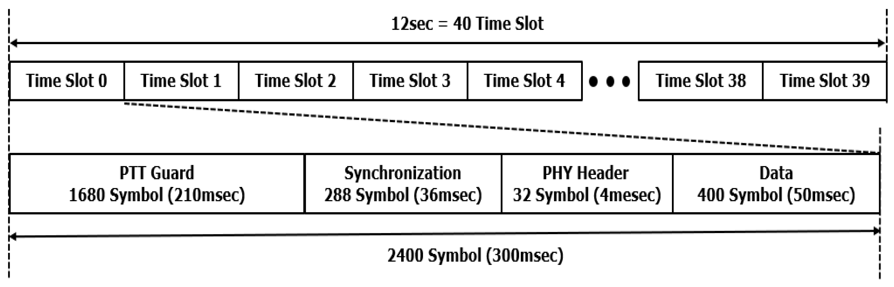
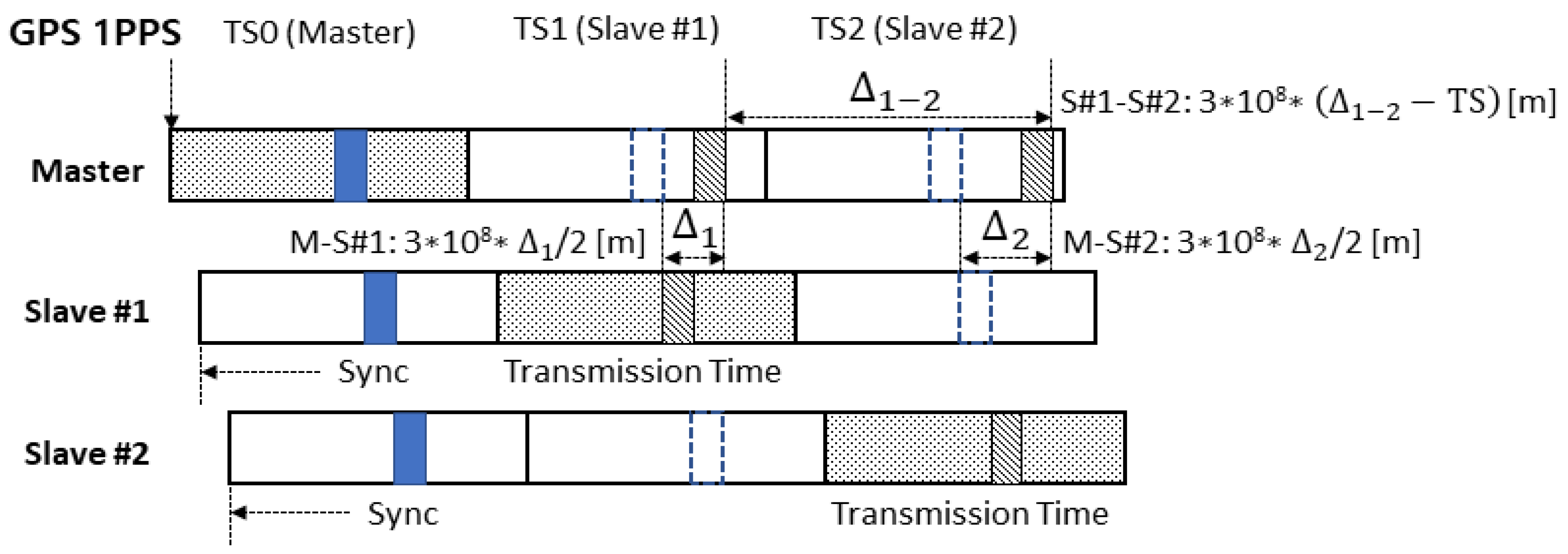
2.1.1. Frame Structure Analysis
2.1.2. Transmitter Analysis
2.1.3. Receiver Analysis
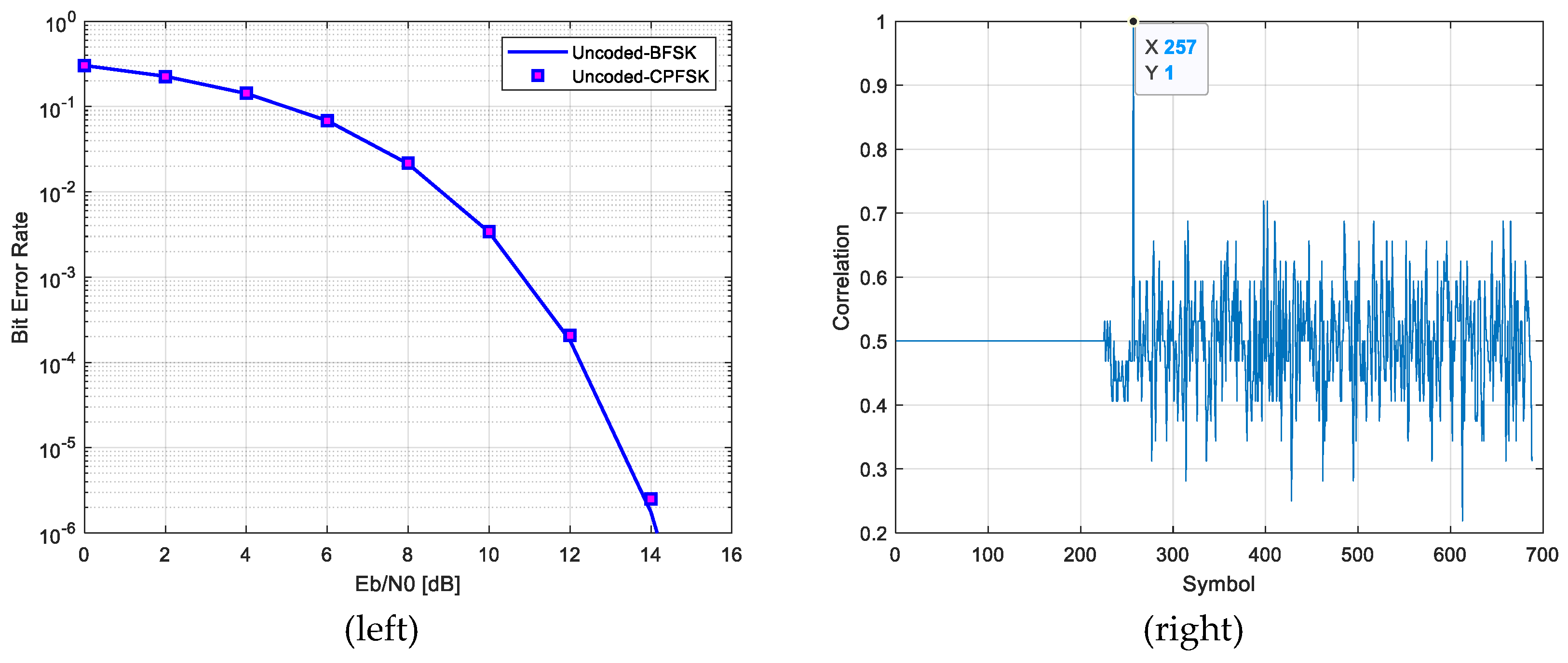
Preamble Detection
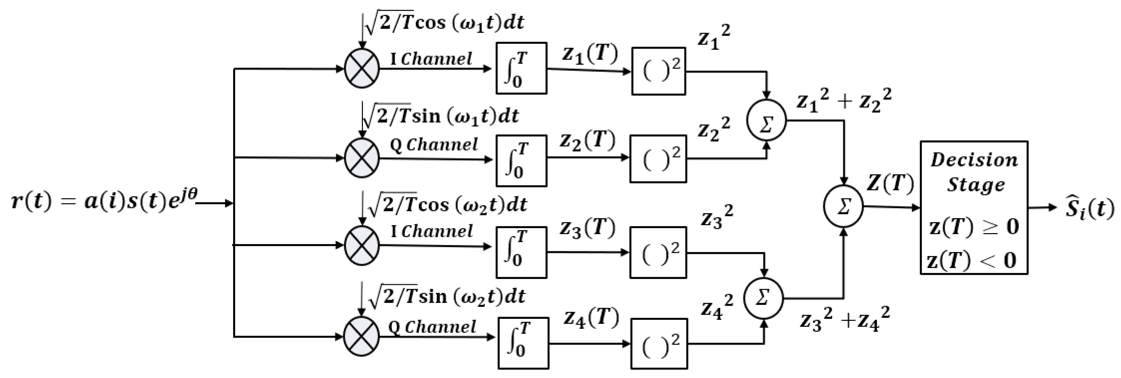
Demodulation
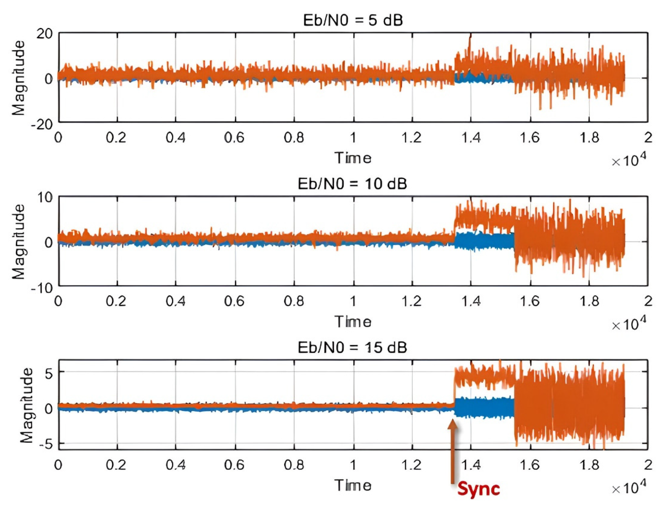
Frame Synchronization
2.2. Design of a Wireless Localization System Using Wireless Communication Frame Structures
3. System Model
3.1. Chirp Spread Spectrum System
3.2. Proposed Chirp-Based Wireless Localization System
3.2.1. Transmitter Design
3.2.2. Jamming Model
3.2.3. Channel Model
3.2.4. Receiver Design
4. Chirp-Based Wireless Localization Algorithm
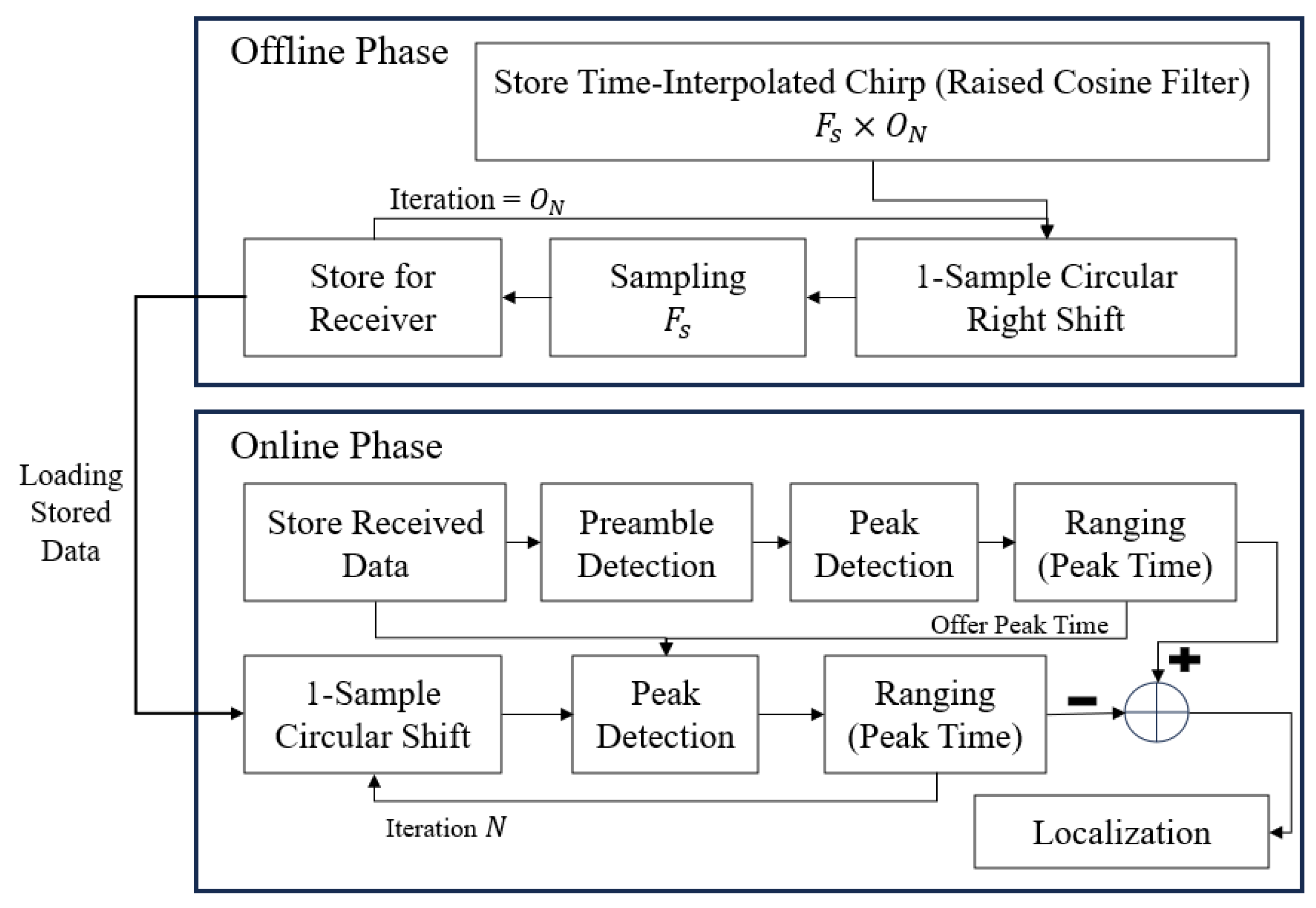
4.1. Design of the Chirp-Based Ranging Enhancement Algorithm
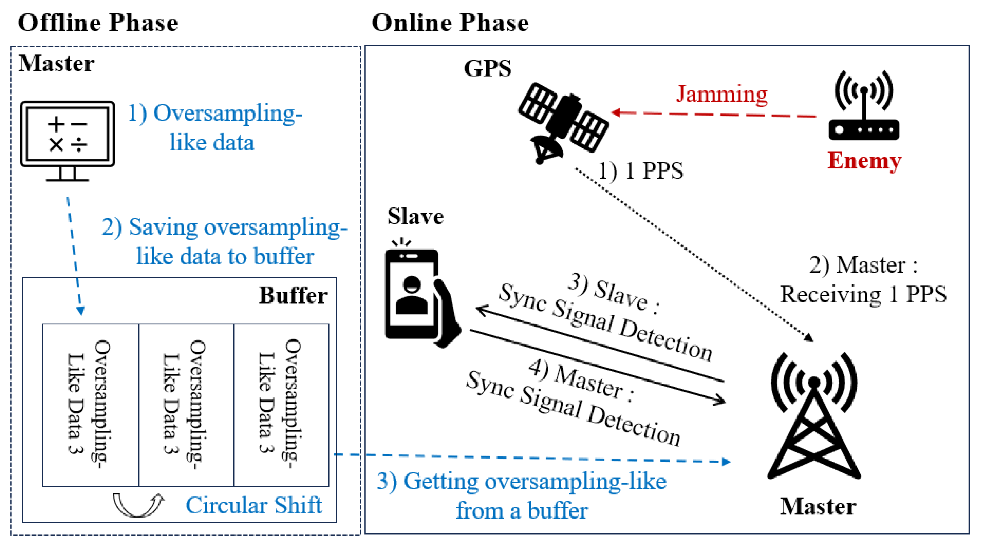
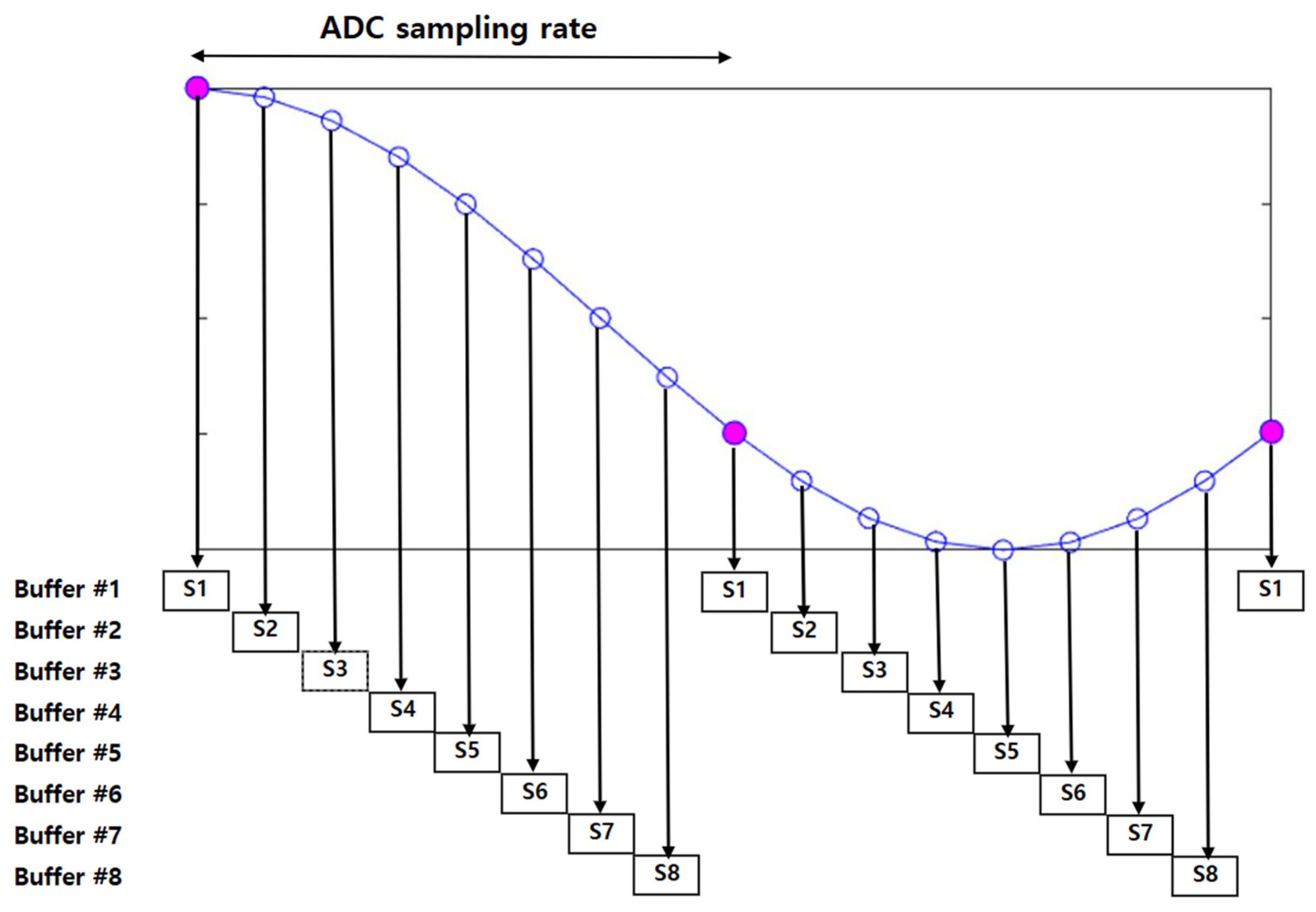
4.1.1. Offline Phase
4.1.2. Online Phase
4.2. Design of the Chirp-Based Localization Enhancement Algorithm
5. Experimental Results and Analysis
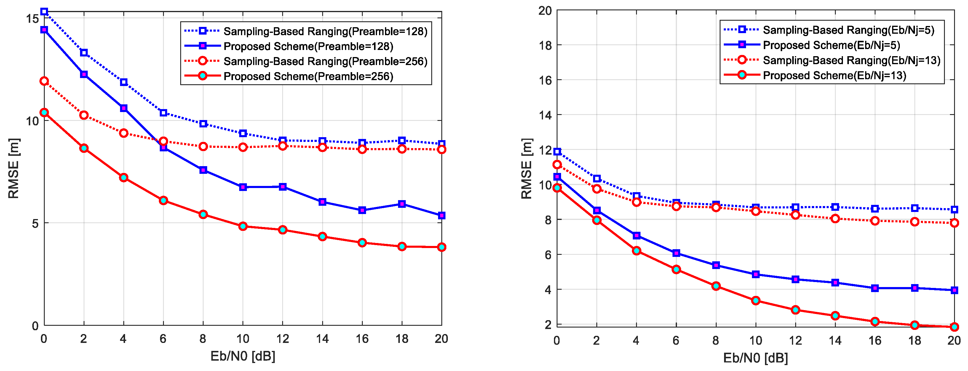
5.1. Ranging Performance
5.2. Wireless Localization Performance
6. Conclusions
Author Contributions
Funding
Institutional Review Board Statement
Informed Consent Statement
Data Availability Statement
Conflicts of Interest
References
- Drawil, N.M.; Amar, H.M.; Basir, O.A. GPS localization accuracy classification: A context-based approach. IEEE Trans. Intell. Transp. Syst. 2013, 14, 262–273. [Google Scholar]
- Cheng, B.; Du, R.; Yang, B.; Yu, W.; Chen, C.; Guan, X. An accurate GPS-based localization in wireless sensor networks: A GM-WLS method. In Proceedings of the International Conference Parallel Processing Workshops (ICPPW), Taipei, Taiwan, 13–16 September 2011; pp. 35–41. [Google Scholar]
- Tiwari, A.; Kumar, M. A review of range based localization techniques in wireless sensor networks. SSRG Int. J. Electron. Commun. Eng. 2021, 8, 1–5. [Google Scholar] [CrossRef]
- Zhang, Y.; Wu, W.; Chen, Y. A range-based localization algorithm for wireless sensor networks. J. Commun. Net. 2005, 7, 429–437. [Google Scholar] [CrossRef]
- He, T.; Huang, C.; Blum, B.M.; Stankovic, J.A.; Abdelzaher, T. Range-free localization schemes for large scale sensor networks. In Proceedings of the 9th Annual Interntaional Conference on Mobile Computing and Networking (MobiCom ’03), San Diego, CA, USA, 14–19 September 2003; pp. 81–95. [Google Scholar]
- Zhang, R.; Cheng, L.; Zhang, W.; Guan, X.; Cai, Y.; Wu, W.; Zhang, R. Channel estimation for movable-antenna MIMO systems via tensor decomposition. IEEE Wirel. Commun. Lett. 2024, 13, 3089–3093. [Google Scholar] [CrossRef]
- Zhang, R.; Wu, X.; Lou, Y.; Yan, F.; Zhou, Z.; Wu, W.; Yuen, C. Channel-training-aided target sensing for terahertz integrated sensing and massive MIMO communications. IEEE Internet Things J. 2025, 12, 3755–3761. [Google Scholar] [CrossRef]
- Cao, Y.; Chen, C.; St-Onge, D.; Beltrame, G. Distributed TDMA for mobile UWB network localization. IEEE Internet Things J. 2021, 8, 13449–13461. [Google Scholar]
- Chen, X.; Chen, Y.; Cao, S.; Zhang, L.; Chen, X. Acoustic indoor localization system integrating TDMA+FDMA transmission scheme and positioning correction techniques. Sensors 2019, 19, 2353. [Google Scholar] [CrossRef]
- Gabbrielli, A.; Fischer, G.K.J.; Schaechtle, T.; Xiong, W.; Schott, D.J.; Bordoy, J.; Wendeberg, J.; Hoflinger, F.; Schindelhauer, C.; Rupitsch, S.J. Airborne acoustic chirp spread spectrum communication system for user identification in indoor localization. IEEE Trans. Instrum Meas. 2023, 72, 9507415. [Google Scholar]
- Wang, J.; Gao, Q.; Yu, Y.; Wang, H.; Jin, M. Toward robust indoor localization based on Bayesian filter using chirp-spread-spectrum ranging. IEEE Trans. Ind. Electron. 2012, 59, 1622–1629. [Google Scholar] [CrossRef]
- Perry, M.; O’Hara, K.; Sellen, A.; Brown, B.; Harper, R. Dealing with mobility: Understanding access anytime, anywhere. ACM Trans. Comput. Hum. Interact. 2001, 8, 323–347. [Google Scholar]
- Kim, K.-Y.; Shin, Y. A data rate improvement scheme for frequency-hopping chirp spread spectrum systems. In Proceedings of the KICS Summer Conference, Jeju, Republic of Korea, 22–24 June 2022; pp. 201–205. [Google Scholar]
- Part 15.4: Wireless Medium Access Control (MAC) and Physical Layer (PHY) Specifications for Low-Rate Wireless Personal Area Networks (WPANs), Mar. 2007. Available online: https://people.ece.ubc.ca/~edc/7860/data/802.15.4-2006.pdf (accessed on 1 January 2025).
- Namgoong, W. ADC and AGC requirements of a direct-sequence spread spectrum signal. In Proceedings of the 44th IEEE 2001 Midwest Symposium on Circuits and Systems (MWSCAS), Dayton, OH, USA, 14–17 August 2001; pp. 744–747. [Google Scholar]
- Lei, Z.; Yang, P.; Zheng, L. Detection and frequency estimation of frequency hopping spread spectrum signals based on channelized modulated wideband converters. Electronics 2018, 7, 170. [Google Scholar] [CrossRef]
- Alliance, L. LoRaWAN What is It? A Technical Overview of LoRa and LoRaWAN. 2015. Available online: https://resources.lora-alliance.org/document/what-is-lorawan (accessed on 17 September 2019).
- Springer, A.; Gugler, W.; Huemer, M.; Reindl, L.; Ruppel, C.C.W.; Weigel, R. Spread spectrum communications using chirp signals. In Proceedings of the IEEE EUROCOMM, Munich, Germany, 19 May 2000; pp. 166–170. [Google Scholar]
- Wang, X.; Fei, M.; Li, X. Performance of chirp spread spectrum in wireless communication systems. In Proceedings of the 2008 11th IEEE Singapore International Conference on Communication Systems, Guangzhou, China, 19–21 November 2008; pp. 466–469. [Google Scholar]
- Robson, S.; Haddad, M. A Chirp Spread Spectrum Modulation Scheme for Robust Power Line Communication. IEEE Trans. PowerDeliv. 2021, 37, 5299–5309. [Google Scholar] [CrossRef]
- Kim, S.; Shim, B. Joint DoA and TDoA estimation for mmWave communications using Zadoff-Chu sequence. In Proceedings of the 2022 International Conference on Information and Communication Technology Convergence (ICTC), Jeju, Republic of Korea, 19–21 October 2022; pp. 1210–1212. [Google Scholar]
- Piccinni, G.; Avitabile, G.; Coviello, G. The use of Zadoff-Chu sequences for a new distance measurement technique. In Proceedings of the Third International Congress on Information and Communication Technology (ICICT 2018), London, UK, 27–28 February 2018; pp. 629–637. [Google Scholar]
- Hsu, J.-M.; Lain, W.-B.; Liang, J.-C. A Context-aware push-to-talk service. In Proceedings of the 2008 International Conference on Multimedia and Ubiquitous Engineering, Busan, Republic of Korea, 24–26 April 2008; pp. 586–591. [Google Scholar]
- Lew, C.-G.; Lee, B.-H. Implementation of the automatic switching device for the voice communication between heterogeneous devices. J. Korea Inst. Electron. Commun. Sci. (KIECS) 2015, 10, 1321–1328. [Google Scholar]
- Nam, J.H.; Seo, N.S.; Jang, D.W. A performance study of tactical data link transceiver in TDMA networks. J. Korea Inst. Mil. Sci. Technol. (KIMST) 2010, 13, 388–396. [Google Scholar]
- Maldonado, A.D. Development of an online PTT voice transmission system between cell phones, computers and embedded systems over the internet. In Proceedings of the 2021 3rd East Indonesia Conference on Computer and Information Technology (EIConCIT), Surabaya, Indonesia, 9–11 April 2021; pp. 95–98. [Google Scholar]
- Bari, M.; Doroslovac, M. Distinguishing CPFSK from QAM and PSK Modulations. Circuits Syst. Signal Process. 2016, 35, 1355–1375. [Google Scholar]
- Konara, K.M.S.Y.; Kolhe, M.L.; Sankalpa, W.G.C.A. Grid synchronization of DC energy storage using voltage source inverter with ZCD and PLL techniques. In Proceedings of the 2015 IEEE 10th International Conference on Industrial and Information Systems (ICIIS), Peradeniya, Sri Lanka, 18–20 December 2015; pp. 458–462. [Google Scholar]
- Chen, Z.; Li, Z. Robust precise time difference estimation based on digital zero-crossing detection algorithm. IEEE Trans. Instrum. Meas. 2016, 65, 1739–1748. [Google Scholar]
- Cao, S.; Qin, H.; Cong, L.; Huang, Y. TDMA datalink cooperative navigation algorithm based on INS/JTIDS/BA. Electronics 2021, 10, 782. [Google Scholar] [CrossRef]
- Lanzisera, S.; Zats, D.; Pister, K.S.J. Radio frequency time-of-flight distance measurement for low-cost wireless sensor localization. IEEE Sens. J. 2011, 11, 837–845. [Google Scholar]
- Gangula, R.; Melodia, T.; Mundlamuri, R.; Kaltenberger, F. Round trip time estimation utilizing cyclic shift of uplink reference signal. arXiv 2023, arXiv:2304.19618. [Google Scholar]
- Kim, K.-Y.; Shin, Y. A multiple chirp based inter-relay interference mitigation technique for two-path successive relaying protocol. J. KICS 2019, 44, 38–47. [Google Scholar]
- Kim, K.-T.; Kim, K.-Y.; Shin, Y. A technique for improving wireless localization precision using chirp signals. J. KICS 2024, 49, 207–210. [Google Scholar] [CrossRef]
- Kim, K.-Y.; Shin, Y. Analysis on cross-correlation coefficient for survivability of chirp spread spectrum systems. IEEE Trans. Inf. Forensics Secur. 2020, 15, 1959–1967. [Google Scholar]
- Noh, H.; Kim, J.; Lim, J.; Nam, J.; Jang, D. Anti-jamming performance analysis of Link-16 waveform. J. KICS 2010, 35, 10–12. [Google Scholar]
- Wu, Z.; Zhao, Y.; Yin, Z.; Luo, H. Jamming signals classification using convolutional neural network. In Proceedings of the 2017 IEEE International Symposium on Signal Processing and Information Technology (ISSPIT), Bilbao, Spain, 18–20 December 2017; pp. 62–67. [Google Scholar]
- Jung, H.; Nguyen, B.V.; Song, I.; Kim, K. Design of anti-jamming waveforms for time-hopping spread spectrum systems in tone jamming environments. IEEE Trans. Veh. Technol. 2020, 69, 728–737. [Google Scholar]
- Liu, J. Wireless multipath fading channels modeling and simulation based on Sum-of-Sinusoids. In Proceedings of the 2016 First IEEE International Conference on Computer Communication and the Internet (ICCCI), Wuhan, China, 13–15 October 2016; pp. 165–168. [Google Scholar]
- Chanvan, M.S.; Chile, R.H.; Sawant, S.R. Multipath fading channel modeling and performance comparison of wireless channel models. Int. J. Electron. Commun. Eng. (IJECE) 2011, 4, 189–203. [Google Scholar]
- Roy, A.; Doherty, J.F. Raised cosine interpolation for empirical mode decomposition. In Proceedings of the 2009 43rd Annual Conference on Information Sciences and Systems, Baltimore, MD, USA, 18–20 March 2009; pp. 888–892. [Google Scholar]
- Lin, Y.; Tsai, H.F.; Jiang, Z.H. Interpolation filter using raised cosine pulse for timing recovery. In Proceedings of the IEEE International Symposium on Communications and Information Technology, Sapporo, Japan, 26–29 October 2004; Volume 1, pp. 200–203. [Google Scholar]
- Eom, S.-S.; Ko, Y.-C. A new signal processing technique for improve PAPR performance. In Proceedings of the Korean Society of Broadcast Engineers Conference, Seoul, Republic of Korea, 18–19 November 2021; pp. 211–213. [Google Scholar]
- Mao, G.; Fidan, B.; Anderson, B.D.O. Wireless sensor network localization techniques. Comput. Netw. 2007, 51, 2529–2553. [Google Scholar]
- Mofeed, M.A.E.; Mofeed, H.A.E. Direction-of-arrival methods (DOA) and time difference of arrival (TDOA) position location technique. In Proceedings of the Twenty-Second National Radio Science Conference, Cairo, Egypt, 15–17 March 2005; pp. 173–182. [Google Scholar]
- Zhou, T.; Cheng, Y. Positioning algorithm of UWB based on TDOA technology in indoor environment. In Proceedings of the 2021 11th International Conference on Information Technology in Medicine and Education (ITME), Wuyishan, China, 19–21 November 2021. [Google Scholar]
- Lyakhov, P.; Valueva, M.; Valuev, G.; Nagornov, N. High-performance digital filtering on truncated multiply-accumulate units in the residue number system. IEEE Access 2020, 8, 209181–209190. [Google Scholar]
- Schroder, Y.; Reimers, D.; Wolf, L. Accurate and precise distance estimation from phase-based ranging data. In Proceedings of the 2018 International Conference on Indoor Positioning and Indoor Navigation (IPIN), Nantes, France, 24–27 September 2018; pp. 1–8. [Google Scholar]
- Zhang, J.; Liu, Z.; Jiang, W.; Liu, Y.; Liu, S.; Liu, L. From coarse to fine: ISAR object view interpolation via flow estimation and GAN. IEEE Trans. Geosci. Remote Sens. 2024, 62, 4706820. [Google Scholar]
- Hua, M.; Wang, M.; Yang, K.W.; Zou, K.J. Analysis of the frequency offset effect on Zadoff-Chu sequence timing performance. IEEE Trans. Commun. 2014, 62, 4024–4039. [Google Scholar]
- De Angelis, A.; Moschitta, A.; Comuniello, A. TDoA based positioning using ultrasound signals and wireless nodes. arXiv 2017, arXiv:1710.07052. [Google Scholar]
- Cheng, B.; Huang, Y.; Zou, C. Robust indoor positioning with smartphone by utilizing encoded chirp acoustic signal. Sensors 2024, 24, 6332. [Google Scholar] [CrossRef] [PubMed]
- Kaltiokallio, O.; Ge, Y.; Talvitie, J.; Wymeersch, H.; Valkama, M. mmWave simultaneous localization and mapping using a computationally efficient EK-PHD filter. arXiv 2021, arXiv:2108.01645. [Google Scholar]
- Gedalyahu, K.; Eldar, Y.C. Time delay estimation from low rate samples: A union of subspaces approach. IEEE Trans. Signal Process. 2010, 58, 3017–3031. [Google Scholar]
- Li, Z.; Dimitrova, D.C.; Raluy, D.H.; Braun, T. TDOA for narrow-band signal with low sampling rate and imperfect synchronization. In Proceedings of the 2014 7th IFIP Wireless and Mobile Networking Conference (WMNC), Vilamoura, Portugal, 20–22 May 2014; pp. 1–8. [Google Scholar]


| Parameter | Value |
|---|---|
| Chirp Duration, | 125s |
| Chirp Bandwidth, | 1 MHz |
| Preamble Sequence | Zadoff–Chu |
| Preamble Length | 128, 256 |
| Distance | 1 km |
| Sampling Rate | 16.384 MHz |
| 5 dB, 13 dB | |
| Pulse Duration Ratio | 0.1 for 1 MHz |
| Channel | AWGN |
| Parameter | Value |
|---|---|
| s | |
| 900 kHz | |
| Preamble Sequence | Zadoff–Chu |
| Preamble Length | 256 |
| Distance | 1 km |
| Sampling Rate | 2.048 MHz |
| 5 dB | |
| Pulse Duration Ratio | 0.1 for 900 kHz |
| Channel | AWGN, Rayleigh, Rician |
| -Factor | 7 |
Disclaimer/Publisher’s Note: The statements, opinions and data contained in all publications are solely those of the individual author(s) and contributor(s) and not of MDPI and/or the editor(s). MDPI and/or the editor(s) disclaim responsibility for any injury to people or property resulting from any ideas, methods, instructions or products referred to in the content. |
© 2025 by the authors. Licensee MDPI, Basel, Switzerland. This article is an open access article distributed under the terms and conditions of the Creative Commons Attribution (CC BY) license (https://creativecommons.org/licenses/by/4.0/).
Share and Cite
Kim, K.-T.; Kim, K.-Y.; Shin, Y. Improvement of Wireless Localization Precision Using Chirp Signals. Sensors 2025, 25, 1844. https://doi.org/10.3390/s25061844
Kim K-T, Kim K-Y, Shin Y. Improvement of Wireless Localization Precision Using Chirp Signals. Sensors. 2025; 25(6):1844. https://doi.org/10.3390/s25061844
Chicago/Turabian StyleKim, Ki-Tae, Kwang-Yul Kim, and Yoan Shin. 2025. "Improvement of Wireless Localization Precision Using Chirp Signals" Sensors 25, no. 6: 1844. https://doi.org/10.3390/s25061844
APA StyleKim, K.-T., Kim, K.-Y., & Shin, Y. (2025). Improvement of Wireless Localization Precision Using Chirp Signals. Sensors, 25(6), 1844. https://doi.org/10.3390/s25061844