1. Introduction
Cobalt is an important mineral resource widely used in aerospace, aviation, automotive, chemical, ceramics, and other industries. Marine cobalt crust resources are richer than those on land, mainly existing attached to bedrock, but the surface coverage is only about 50% [
1]. With continuous surveys since the end of the last century, research on seafloor cobalt crusts has shifted from mining area detection to exploration and extraction [
2]. Real-time identification of cobalt crusts is a crucial prerequisite for mining; therefore, accurately detecting and identifying the distribution of deep-sea cobalt crust deposits is of great significance.
Currently, underwater target detection mainly employs two methods: sonar detection and optical imaging. Sonar detection has the advantages of a wide detection range and strong anti-interference capability, but, due to limitations in the number of beams and recognition accuracy, the efficiency of substrate identification within the area is not high. Optical imaging methods can obtain richer and more intuitive information, enhancing recognition efficiency and accuracy. However, during actual mining operations, sediment stirred up by mining equipment can significantly interfere with imaging effects, causing images to become blurred and “foggy”, leading to the loss of target details. To achieve precise excavation and minimize the image degradation effects caused by suspended particles, further research on imaging technology in turbid underwater environments is necessary.
Underwater image processing technologies are mainly divided into image enhancement techniques based on pixel transformation and image restoration methods based on degradation models. Common methods include histogram-based processing, Retinex theory-based methods, image fusion, and deep learning-based underwater image enhancement [
3]. These methods process images by directly manipulating pixels or by inversely solving degradation models, with their effectiveness directly dependent on the original image and the constructed prior model. However, due to the lack of information about actual interference sources and the inability to avoid inherent interference from suspended particles present in the scene, the fundamental problem of reduced image clarity remains unsolved, limiting the ability to restore target details.
In contrast, polarization imaging is based on physical imaging models. By capturing images of the same scene under different polarization states and exploiting the differences in polarization characteristics between scattered light and target signal light, it calculates the degree of polarization of backscattered light and the transmission coefficient. This enables the separation of scattered light from the target signal light, thereby achieving clearer imaging. In 2003 and 2005, Schechner et al. proposed a polarization imaging model and a passive underwater polarization imaging model, respectively [
4,
5], marking the first introduction of underwater imaging de-scattering models. However, in practical applications, due to the high attenuation coefficient in underwater environments and the weakness of natural illumination, imaging requirements are not met, researchers began adopting active illumination in polarization imaging systems. Treibitz et al. [
6] proposed an active polarization de-scattering model in turbid water. One of the assumptions of this method is that the degree of polarization of background scattered light is constant. Under active illumination, the light field is non-uniform, leading to an uneven spatial distribution of the degree of polarization of background scattered light in the scene. This makes it difficult to fully suppress backscattered light, and issues of image detail degradation and uneven illumination still exist.
To more accurately calculate the spatial distribution of the degree of polarization of scattered light and improve imaging quality, researchers have studied this from different perspectives. Liu et al. [
7] proposed an underwater image restoration method based on Stokes decomposition, but this method requires orthogonal polarized illumination, increasing the requirements for experimental equipment. Li et al. [
8] obtained the degree of polarization of experimental objects and background scattered light using optimization algorithms but ignored the global differences in the degree of polarization within the image. Hu et al. [
9] removed the light from the target object area of the polarized image and used information from the background area to perform polynomial fitting on the light intensity and degree of polarization in the target object area, estimating a more accurate global degree of polarization value. However, the experiments in this study were conducted in a water tank constructed with acrylic plates, the camera’s shooting range was small, and the target objects were simple, with low grayscale levels used. This differs significantly from wide water environments, limiting the applicability of the method. Wang et al. [
10] suppressed the impact of active illumination non-uniformity through frequency-domain homogenization and polarization-weighted fusion. However, the local DoLP-based weight calculation inadequately corrected the global spatial distribution differences in the polarization degree of scattered light, which may result in residual gradient effects under complex light fields. Shen et al. [
11] mitigated scattering and illumination non-uniformity through iterative polarization optimization. However, the globally uniform scattering correction parameters failed to adapt to local polarization attenuation variations in complex substrates, which may lead to reduced stability in detail reconstruction for highly heterogeneous seabed regions. Li et al. [
12] mitigated underwater illumination non-uniformity using polarizing lenses and averaging filters. But, the fixed parameter set for scattering light correction failed to adapt to spatial variations in complex seabed environments, resulting in unstable scattering suppression performance within high-turbidity zones.
Homomorphic filtering (HF) combines frequency filtering and spatial gray-level transformation. Based on the illumination–reflectance model of images as the foundation for frequency domain processing, setting appropriate parameters can compress the global brightness range, meeting image restoration requirements in complex scenes. Therefore, to mitigate the effects of uneven active illumination and address the uneven distribution of the global degree of polarization in scattering in images without significantly increasing system complexity, this paper incorporates homomorphic filtering into the classical polarization restoration method. By applying homomorphic filtering to the original orthogonally polarized images, the contrast of the images is enhanced, and the light intensity is balanced. While maintaining the polarization relationship is unchanged, the corresponding polarization images are obtained, reducing spatial differences in the degree of polarization and suppressing backscattered light. After optimizing various parameters using a genetic algorithm, the polarization restoration algorithm is employed to ultimately achieve clear imaging in turbid water environments.
2. Fundamental Theory
2.1. Underwater Imaging Model
The Jaffe–McGlamery model [
13] is a classic and commonly used underwater imaging model. This model indicates that the total light intensity received by an underwater imaging system is composed of a linear superposition of direct components, forward scattering components, and backscattering components. In turbid water imaging environments, the primary factor leading to image quality degradation is the interference of backscattered light. Neglecting the forward scattering component, the total light intensity
can be expressed as the sum of the target reflected light
and the backscattered light
:
Among them, the target reflected light is the original reflected light (the restored image) that enters the camera after absorption and scattering by particles, represented as the product of the original reflected light and the transmittance .
The target reflected light
is inversely proportional to the transmittance of the backscattered light
. Therefore, the backscattered light is expressed as the product of the backscattered light at infinity
(corresponding to the background region in the image) and the transmittance function
:
By substituting Equations (2) and (3) into Equation (1) and simplifying, formulas for calculating the transmission rate
and the restored image
are derived.
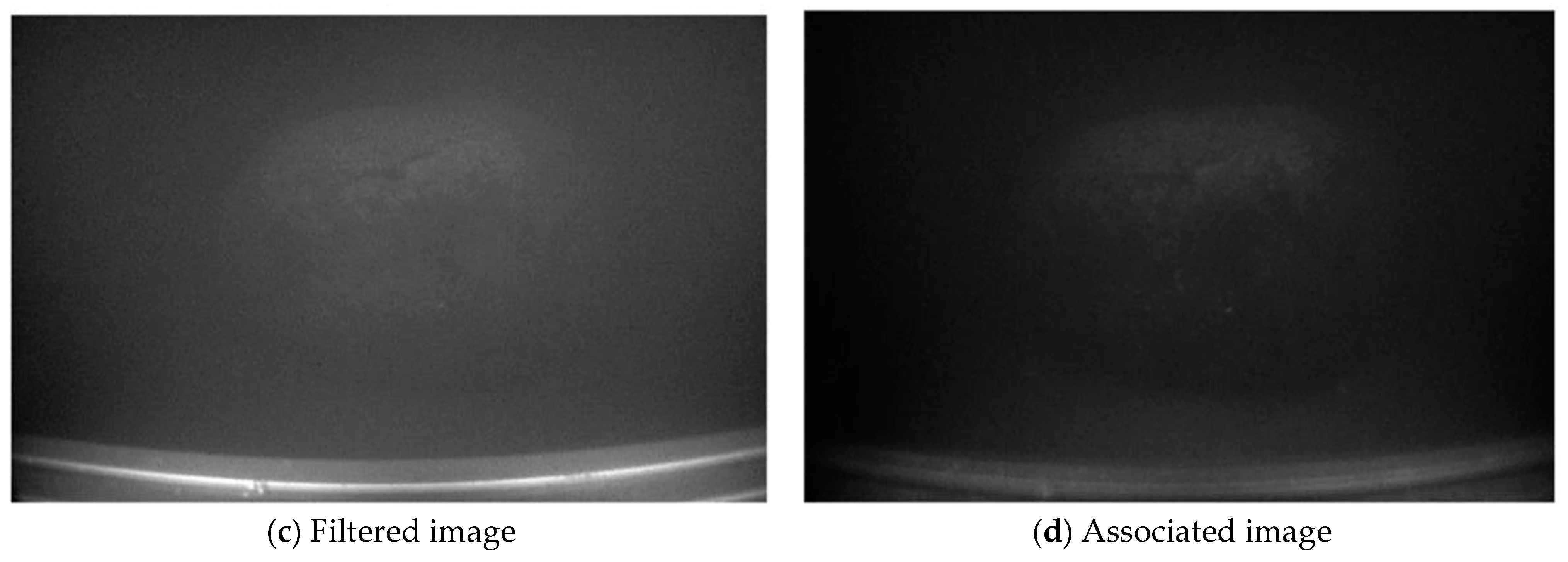
2.2. Orthogonally Polarized Images
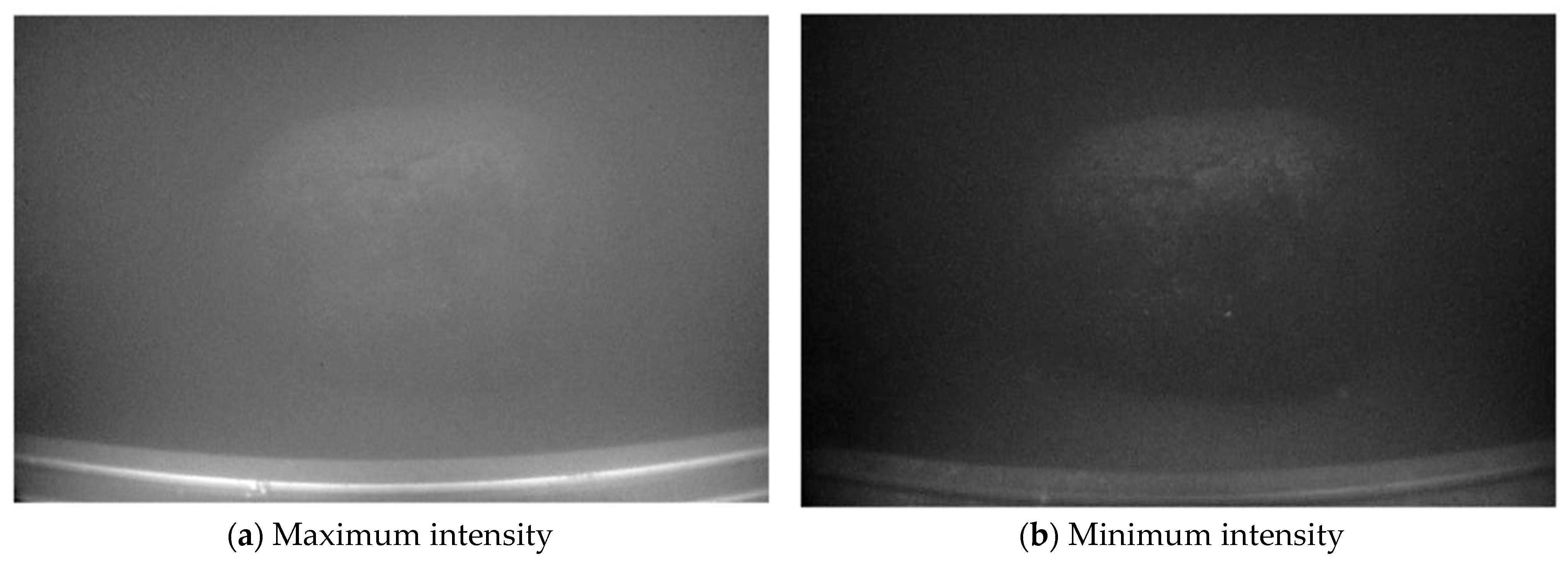
After passing through a fixed linear polarizer (polarizer), the active light source becomes linearly polarized light. By rotating the linear polarizer (analyzer) in front of the camera lens, orthogonally polarized images of the same scene can be captured. When the analyzer is aligned parallel to the polarizer, the maximum intensity image
is obtained; when it is perpendicular, the minimum intensity image
is obtained. The total intensity
is the sum of these two images, combined with Equation (1):
Cobalt crusts exhibit low polarization characteristics due to their irregular surfaces and porous medium properties. Assuming that the polarization direction of the target reflected light
is completely random (unpolarized), we have this equation:
Under this assumption, the target reflected light components
in both the maximum and minimum intensity images are equal. Combining Equations (6) and (7), this can be expressed:
Subtracting Equation (9) from Equation (8) shows that the difference image between the orthogonally polarized images
equals the difference in backscattered light
:
Due to water interference and the uneven illumination caused by active lighting, the degree of polarization of scattered light varies across the image. Using only the original orthogonally polarized images and , traditional polarization restoration methods cannot effectively separate the backscattered light from the target reflected light, making it difficult to achieve satisfactory imaging results.
2.3. Homomorphic Filtering Preprocessing
Homomorphic filtering is an image processing method that combines frequency filtering with spatial domain grayscale transformations. Using the illumination–reflectance model of the image as the foundation for frequency domain processing, it can compress the brightness range and enhance contrast. This approach can overcome the shortcomings of traditional polarization restoration methods to a certain extent without complicating the model. The homomorphic filtering applied to an image can be expressed:
where
and
are the high-frequency and low-frequency gains, respectively;
is the sharpening coefficient; and
is the cutoff frequency.
A pair of orthogonally polarized images has a fixed polarization relationship, defined by the global degree of polarization
:
To maintain the inherent polarization relationship of the orthogonally polarized images after filtering, homomorphic filtering is applied only to the maximum intensity image
to obtain
. The corresponding minimum intensity image
is then derived using the degree of polarization, ensuring that the degree of polarization of each pair of orthogonally polarized images
remains unchanged before and after filtering [
14,
15]:
2.4. Polarization Restoration
The degree of polarization of the backscattered light in the background region
can be expressed as:
where
and
are the horizontally and vertically polarized components of the homomorphic filtered backscattered light, respectively.
The degree of polarization of the backscattered light
is taken from the average value of the background region of the image.
Since
varies across the background region, it is multiplied by a correction coefficient
[
4] to reduce errors. The backscattered light
is then calculated:
The backscattered light at infinity
is obtained by averaging the backscattered light in the background region:
Finally, the transmittance
and the restored image
are calculated:
2.5. Image Quality Assessment and Optimization
To objectively evaluate the restoration effect, we introduce the image enhancement measure (EME) [
16] under no-reference conditions as a quantitative metric for assessing the quality of the restored images:
Here, the image is divided into blocks; and are the maximum and minimum intensities in the -th block; and (set to 0.001) is a infinitesimal value to prevent division by zero. A higher EME value indicates clearer image details and better image quality. Additionally, the EME value serves as the fitness function in the genetic algorithm to optimize the parameters of homomorphic filtering and polarization restoration.
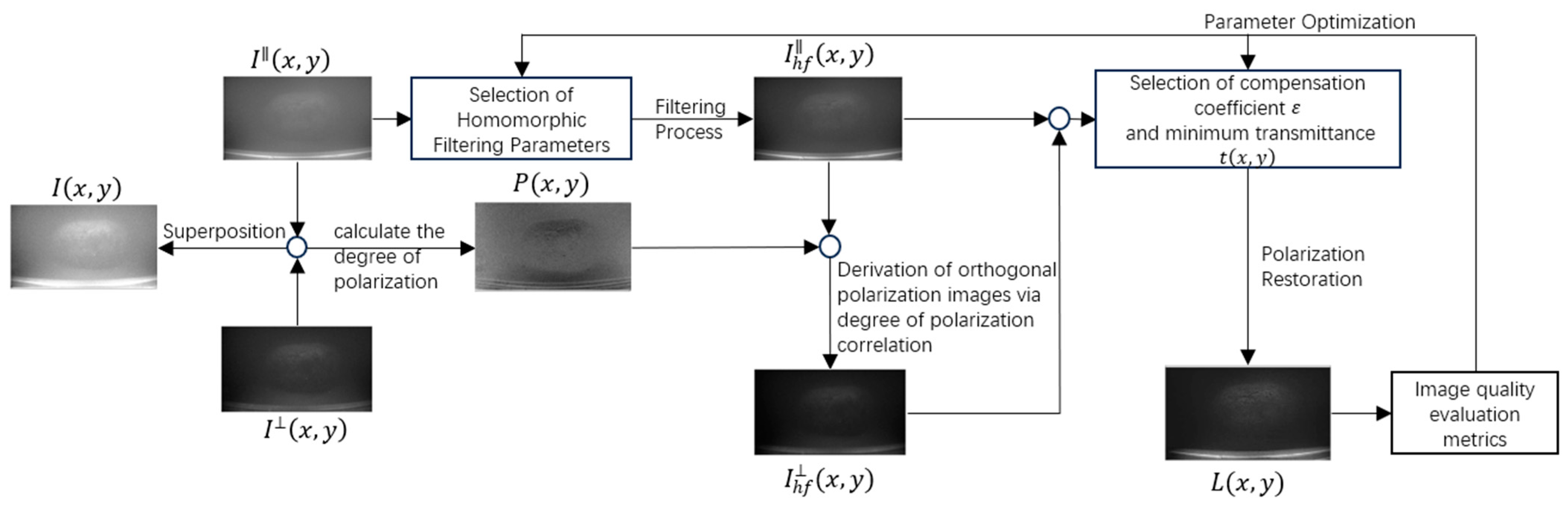
2.6. Polarization Image Restoration Procedure
The following is a flowchart of the proposed method: see
Figure 1.
The method proposed begins by acquiring the original image , along with its horizontal and vertical polarization components. The degree of polarization is calculated by superimposing and . Subsequently, homomorphic filtering is applied to , resulting in the filtered image . Based on and , the corresponding orthogonal polarization image is derived. Polarization restoration is performed by selecting the compensation coefficient and minimum transmittance , yielding the final restored image . Finally, image quality evaluation metrics (EME) are employed to assess , the EME assessment also served as fitness function to optimize the parameters of homomorphic filtering and polarization restoration.
5. Conclusions
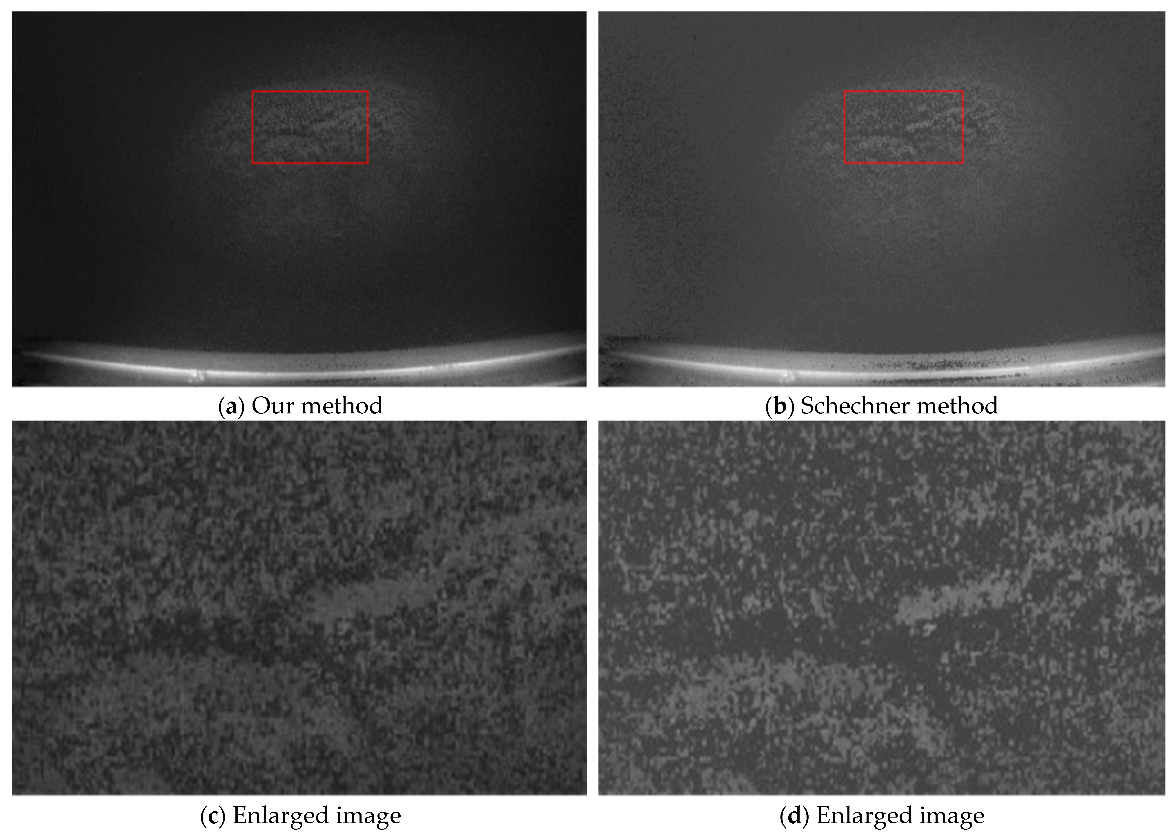
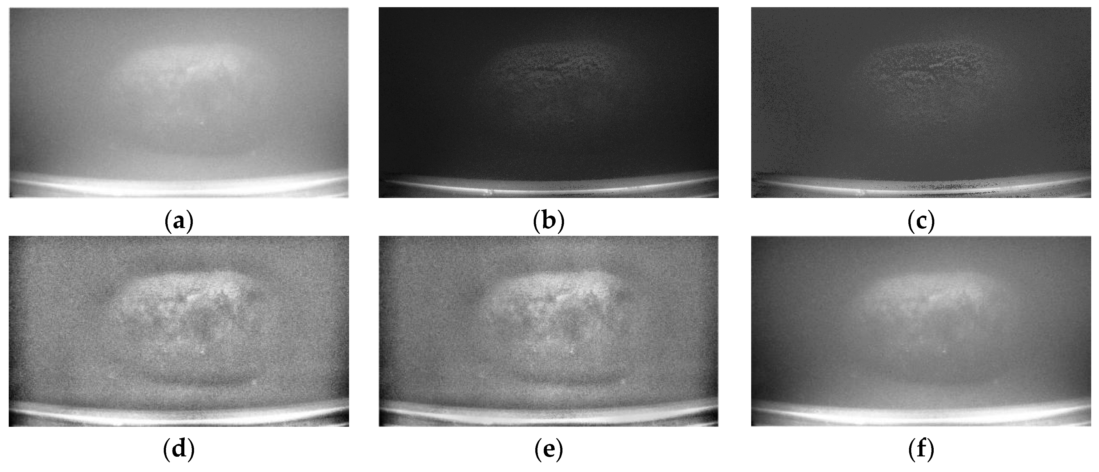
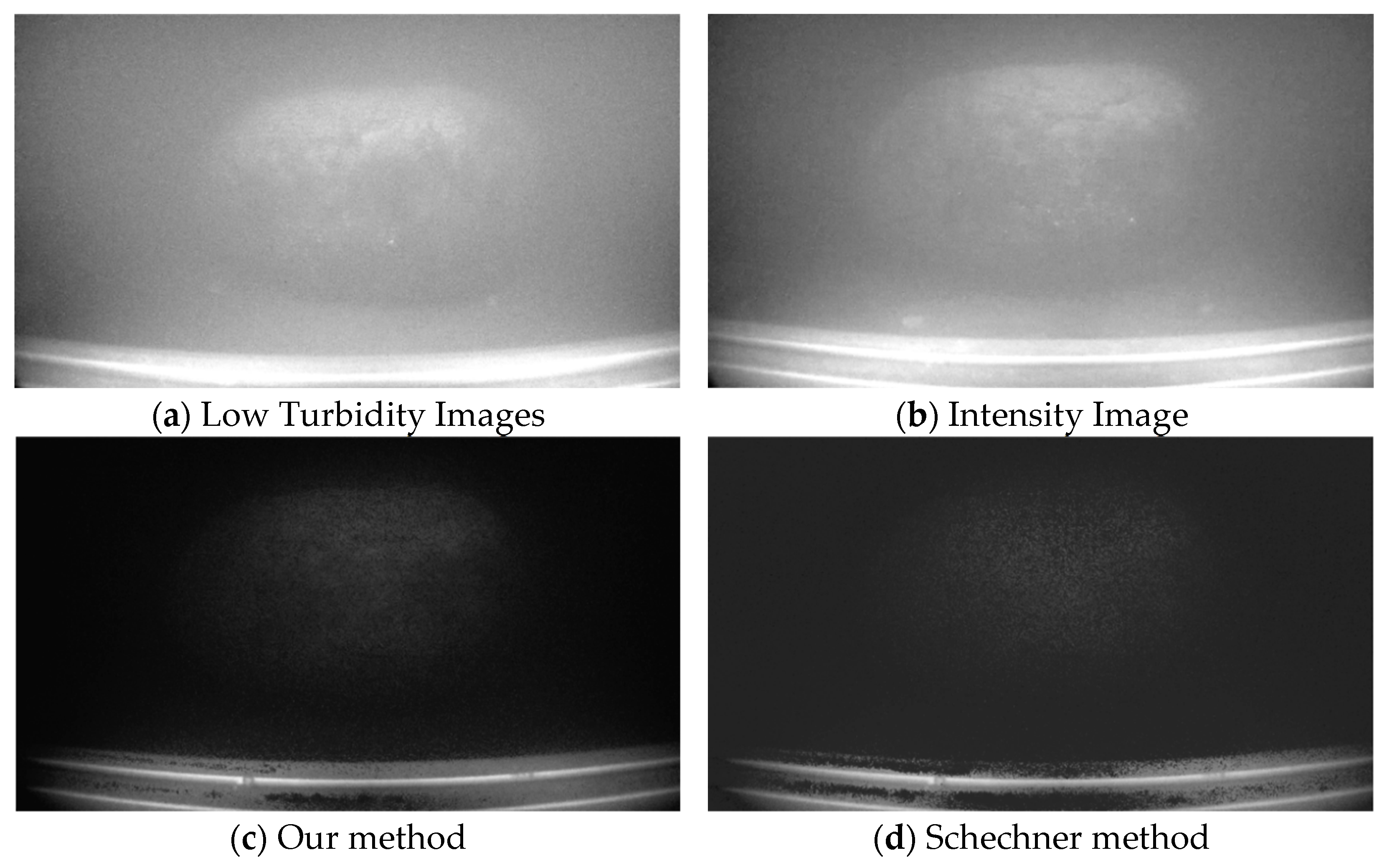
In this paper, an underwater image restoration method combining digital image processing techniques with polarization imaging is proposed to address the imaging requirements of cobalt-rich crusts in deep-sea mining environments. This method effectively integrates homomorphic filtering with classical polarization restoration and introduces a genetic algorithm to optimize parameter values. Addressing the issue of uneven global polarization degree. Underwater imaging experiments were conducted under different scenarios. The results were compared with other methods using three no-reference image quality evaluation metrics: IC, EME, and BRISQUE. Compared with previous methods, the combination of homomorphic filtering and polarization imaging can effectively suppress scattered light in the background regions of wider water bodies containing sediment deposits, thereby enhancing the contrast of texture details on the surface of the target cobalt-rich crust. Finally, the practical application potential and engineering challenges of this algorithm are analyzed.
Due to experimental limitations, the detection range of the underwater camera was relatively short. Only one cobalt-rich crust sample was placed within the camera’s field of view, and the concentration of suspended particles was relatively uniform. Future research can further explore methods to accurately calculate the global degree of polarization and backscattered light, thereby achieving image restoration in mining environments with non-uniform concentration scenarios.


