1. Introduction
The rapid advancement in wireless communication systems has significantly intensified research within the next-generation 6G communication spectrum, owing to its potential to enable ultra-high-speed data transmission and low-latency connectivity [
1,
2]. A key enabler of 6G systems is Integrated Sensing and Communication (ISAC), which unifies connectivity and environmental mapping [
3], alongside sophisticated techniques like Dual-Functional Radar-Communication (DFRC) beam forming for enhanced spectrum utilization [
4]. The foundational requirement for these systems is the development of high-performance antennas capable of delivering wide bandwidths (BW) and high gain across specific frequency bands.
The distinct characteristics of mmWave frequencies, particularly those above 24 GHz, demand efficient spectrum utilization to support the growing needs of next-generation wireless applications [
5]. In this context, the Centimeter Wave (cmWave) band (7–14 GHz) has also emerged as a critical region, acting as a bridge between the sub-6 GHz and mmWave spectrums to offer an optimal balance of robust coverage and high capacity [
6]. The World Radio communication Conference (WRC) and the International Telecommunication Union Radio communication Sector (ITU-R) have proposed and endorsed several candidate bands for next-generation communications [
7]. Among these, the 28 GHz and 38 GHz bands have gained prominence due to their favorable propagation characteristics and compatibility with existing technological infrastructures [
8,
9].
The demand for compact, low-profile, and planar antenna designs continues to rise in modern wireless communication systems, driven by the need to integrate high-performance components into increasingly space-constrained devices [
10,
11]. Antennas employing innovative geometries and extended ground plane configurations have shown promise in meeting diverse performance requirements while maintaining a minimal physical footprint. In particular, industry and research alike are focused on antennas that are not only cost-effective and lightweight but also capable of delivering broad BW, high gain, radiation efficiency, and stable radiation patterns [
12]. Consequently, the development of highly efficient antennas has become a central theme in antenna design research. However, despite notable progress, achieving miniaturized antenna designs that simultaneously fulfill these stringent performance criteria remains an ongoing challenge for the radio frequency (RF) engineering community.
1.1. Related Work
Over the past few decades, extensive research has focused on planar monopole antennas, exploring diverse design strategies such as the incorporation of slots, slits, and loading stubs to enhance impedance BW, gain, and radiation characteristics [
13,
14,
15,
16,
17,
18]. Among these designs, trowel-shaped planar antennas (TSPAs) have attracted particular interest due to their favorable electromagnetic properties. Nevertheless, achieving miniaturization in TSPA structures remains a significant challenge, as many existing designs struggle to balance reduced physical/electrical dimensions with satisfactory performance metrics.
Recent research efforts have therefore shifted toward developing compact, low-cost antennas capable of delivering wideband performance for emerging wireless applications. Innovative geometries and simplified structures have garnered attention owing to their structural simplicity, ease of fabrication, and adaptability, positioning them as strong candidates for next-generation wireless systems. Consequently, numerous novel antenna architectures have been proposed, each seeking to optimize the trade-off between physical size and electromagnetic performance. At mm-wave frequencies, antenna designs increasingly prioritize broad BW, high gain, excellent radiation efficiency, and stable radiation patterns. However, achieving these targets often introduces trade-offs in size, structural complexity, or achievable BW. For example, Zeng et al. [
19] proposed a hook-shaped monopole antenna achieving a fractional bandwidth (FBW) of 59.2% from the range of operating frequency of (21.82–40.17 GHz) and a peak gain of 6.5 dB, incorporating multiple elements such as a rectangular stub and triangular patch on a Rogers RO5880 substrate. Despite its merits, this design exhibits limited BW and structural complexity. Although its ultra-wideband coverage supports applications like 5G NR, Internet of Things (IoT), and high-speed wireless systems, further BW improvement and simplification are desirable. Similarly, Toktas et al. [
20] introduced a half-elliptic monopole with a defective ground structure, achieving a 76.19% FBW (20.8–46.4 GHz) and a compact size of 0.7λ
0 × 0.7λ
0 × 0.036λ
0 on a Rogers RT/duroid 5880 substrate. However, their design relies on complex ground-plane modifications and still offers a narrower BW compared to the proposed antenna, which achieves a broader 113.05% FBW with a simpler single-layer structure. Additionally, the proposed design maintains a high radiation efficiency of 85% and stable gain (>5 dBi) without resorting to intricate defected ground configurations, enhancing fabrication simplicity and practical applicability. Reconfigurable antennas, such as the design proposed by Shereen et al. [
21], provide dynamic frequency and radiation pattern switching over discrete bands (24.2–26.5 GHz and 27.4–29.8 GHz) using integrated PIN diodes. However, such designs introduce substantial complexity and performance trade-offs, including increased losses and reduced efficiency (peak gain: 4.8 dBi, efficiency ~75%). By contrast, the proposed trowel-shaped planar antenna (TSPA) achieves passive ultra-wideband operation from 15 GHz to 54 GHz without employing active components, thus avoiding the additional losses and complications associated with reconfigurable elements. It offers a compact footprint and superior BW, positioning it as a practical solution for universal mmWave applications.
Further, Wadhwa et al. [
22] reported a design achieving a 79.1% FBW (17.23–40 GHz) and a peak gain of 9.08 dBi using a complex structure incorporating a three-armed H-shaped slot and an inverted T-shaped slot on a low-cost FR-4 substrate. Although their MIMO array configuration boosts gain to 13.69 dBi, the design entails large physical dimensions and intricate slot patterns, complicating fabrication and integration. In contrast, the proposed TSPA achieves a broader 113.05% FBW with a more compact electrical size 1.05λ
0 × 0.775λ
0 and a single-layer design, avoiding complex slot-based current manipulation while maintaining a stable realized gain above 5 dBi across the entire 13–52 GHz operating band, as shown by simulated and measured results. Wearable antennas, such as the one presented by Li et al. [
23], achieve a FBW of 58.14% from (11.92–21.66 GHz) using flexible monopole structures tailored for wireless body area network (WBAN) applications. However, these designs are confined to lower mmWave frequencies and exhibit larger physical sizes compared to the proposed design. For instance, Kirtania et al. [
24] developed a CPW-fed circular monopole antenna achieving dual-band UWB performance (3.04–10.70 GHz and 15.18–18 GHz, FBW 111.66%) on an ultra-thin PET substrate, offering bending resilience for wearable applications. However, its upper frequency range remains narrower than the proposed antenna’s extensive mmWave coverage. Similarly, the log-periodic antenna proposed in [
25] achieves a 34.73% FBW (25–35.5 GHz) and average gain of 11 dBi on a compact 1.67λ
0 × 3.17λ
0 Arlon DiClad 880™ substrate.
Meanwhile, the multi-band monopole antenna in [
26] achieves operation across five bands up to 20 GHz, but its peak BW and gain remain lower than the proposed design. High-gain solutions such as Wang et al. [
27] employ multi-layer substrate-integrated horns to achieve a 44% BW (25.8–40.2 GHz) but at the cost of increased size and fabrication complexity. Likewise, hybrid structures like the tilted combined beam antenna in [
28] provide narrow BWs (5.4% FBW over 27.2–28.7 GHz) and demand precise element placement to achieve specific beam directions. In contrast, the proposed antenna achieves much broader BW and consistent performance without such structural complexity, ensuring easier integration into diverse mmWave systems.
Moreover, the slotted patch antenna proposed in [
29] achieves a 1.38 GHz BW (17.15–18.53 GHz, 7.8% FBW) with a compact 1.15λ
0 × 0.8λ
0 size on an FR-4 substrate, demonstrating high gain (7.8 dBi) and >89% efficiency. However, its BW is substantially narrower than that of the proposed antenna. Lastly, while antipodal Vivaldi antennas (AVAs) such as those in [
30] offer ultra wideband (UWB) operation with compact dimensions, their operational BW predominantly covers frequencies 4–30 GHz, falling short of the higher mm-wave coverage achieved by the proposed design.
In this work, we present a novel, cost-effective, and high-performance antenna consisting of a trowel-shaped radiator, a triangular tapered feedline, and a partial ground plane, specifically engineered for mmWave wireless communication applications. Fabricated on a Rogers RO5880 substrate, the proposed antenna achieves an ultra-wide FBW of 113.05%, spanning 15 GHz to 54 GHz, with excellent impedance matching (|S11| ≤ −10 dB). With compact electrical dimensions of 1.05λ0 × 0.775λ0 × 0.0254λ0, it delivers stable radiation patterns, high radiation efficiency (>85%), and competitive gain across the entire band, demonstrating clear advantages over existing designs. These features position the proposed antenna as a promising candidate for future 5G NR, IoT, and high-speed mmWave communication systems.
1.2. Key Contributions
The contributions of this work are as follows:
![Sensors 25 07224 i001 Sensors 25 07224 i001]()
The antenna is designed using the proper formulations with a compact dimension of 1.05λ0 × 0.775λ0.
![Sensors 25 07224 i001 Sensors 25 07224 i001]()
An efficient approach towards open-circuit-loaded stubs is employed.
![Sensors 25 07224 i001 Sensors 25 07224 i001]()
The tapered feed section and the cylindrical elliptical stub are carefully positioned at the middle of the substrate, and impedance matching is attainable with flexible utilization of variables.
![Sensors 25 07224 i001 Sensors 25 07224 i001]()
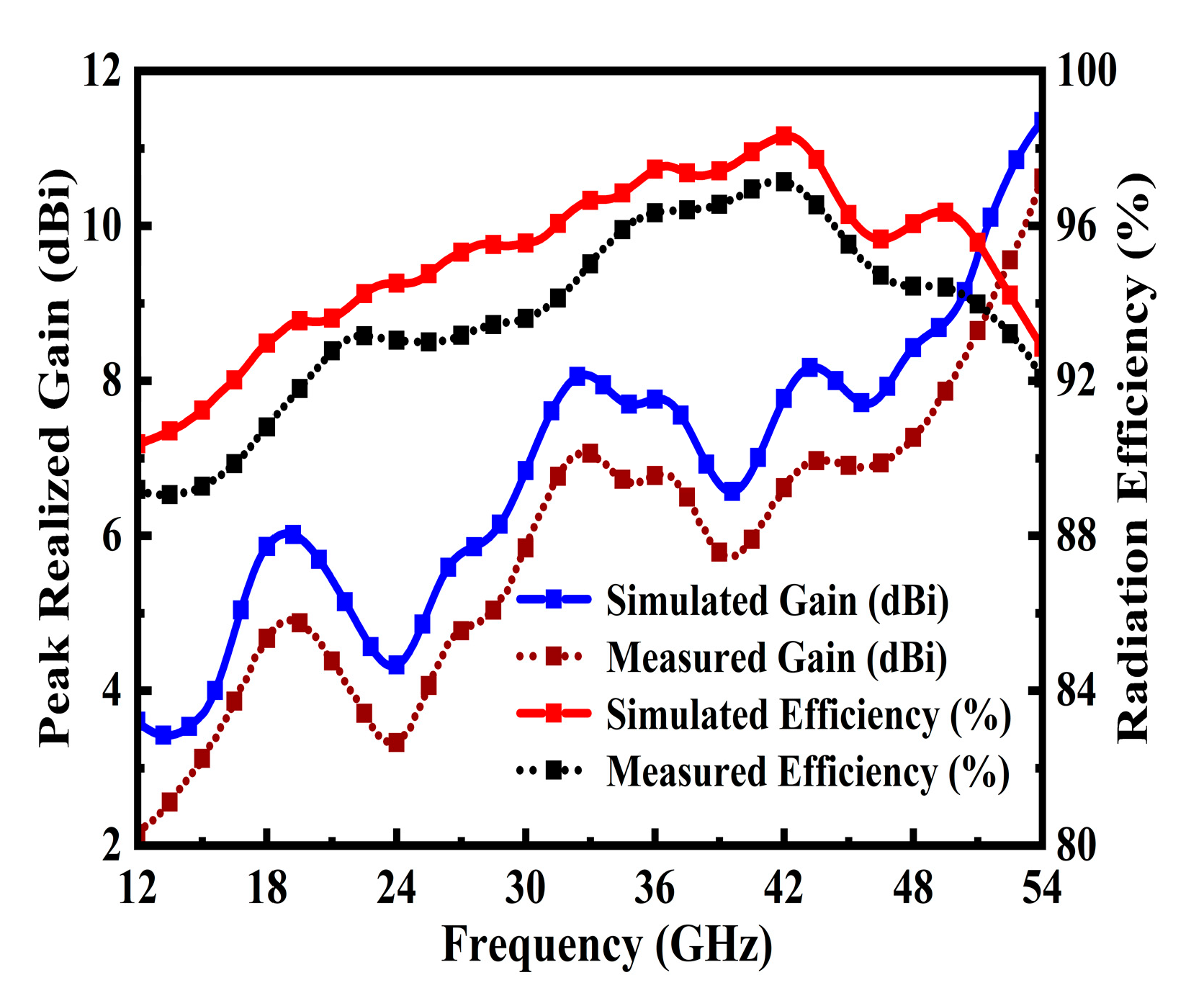
The novel antenna reveals high-performance features such as a broad BW of 39 GHz (ranging from 15 GHz to 54 GHz) at 10 dB return loss, with a maximum gain of 9.67 dBi resonated at 51.8 GHz; optimal radiation efficiency of 97%; intensive current flow through the radiator; and stable far-field radiation patterns.
![Sensors 25 07224 i001 Sensors 25 07224 i001]()
Finally, a comparison between the scientific results with newly published research has been made.
![Sensors 25 07224 i001 Sensors 25 07224 i001]()
The prototype is well-suited for operation within the microwave frequency range, aligning seamlessly with the demands of next-generation 6G wireless communication systems.
1.3. Manuscript Structure
The rest of the paper is structured as follows:
Section 2 presents the theoretical analysis of the antenna design.
Section 3 describes the antenna configuration, parametric studies, and optimization.
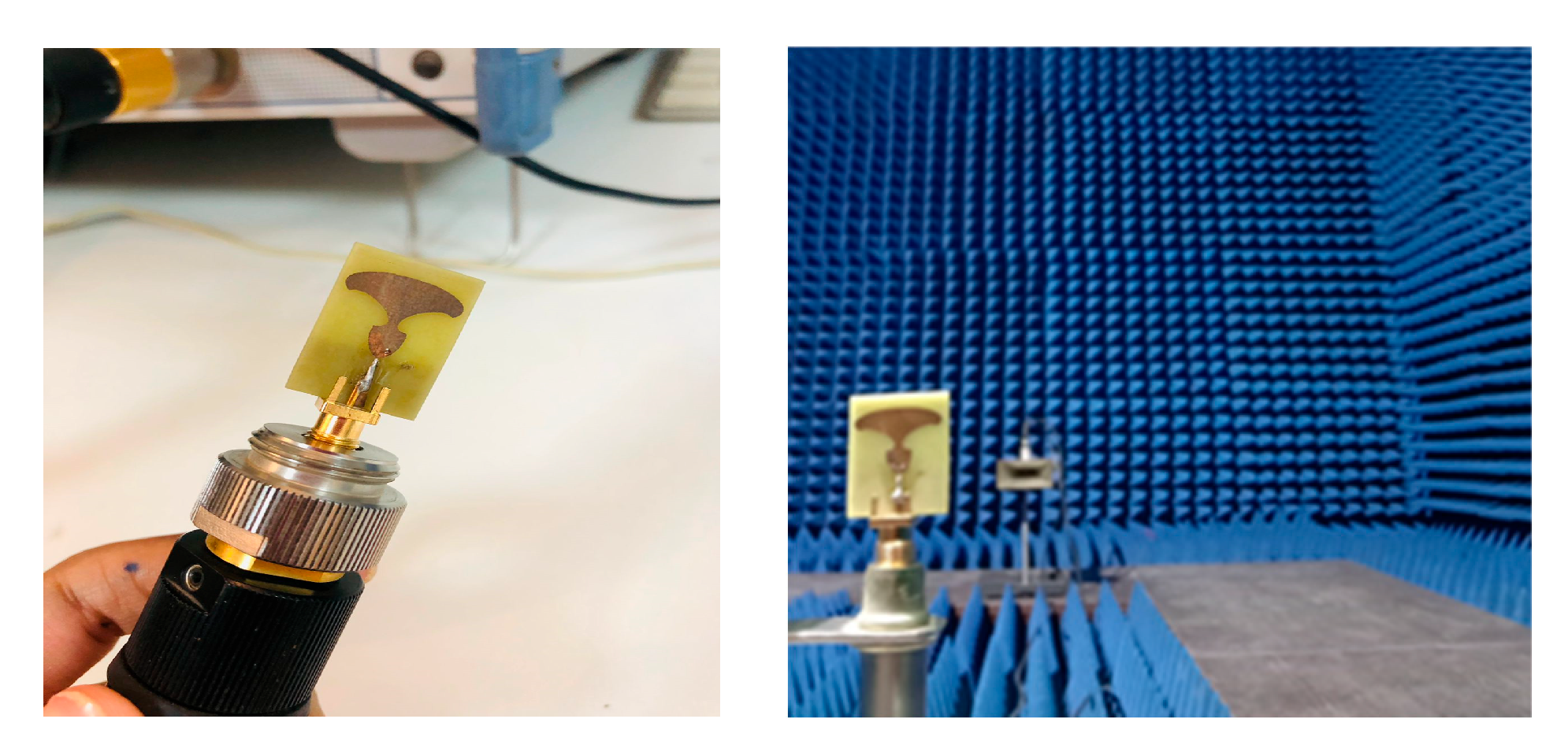
Section 4 details the simulated results, performance discussion and covers fabrication and experimental validation.
Section 5 compares the proposed design with recent state-of-the-art antennas. Finally,
Section 6 provides concluding remarks and suggestions for future research.
2. Theoretical Analysis
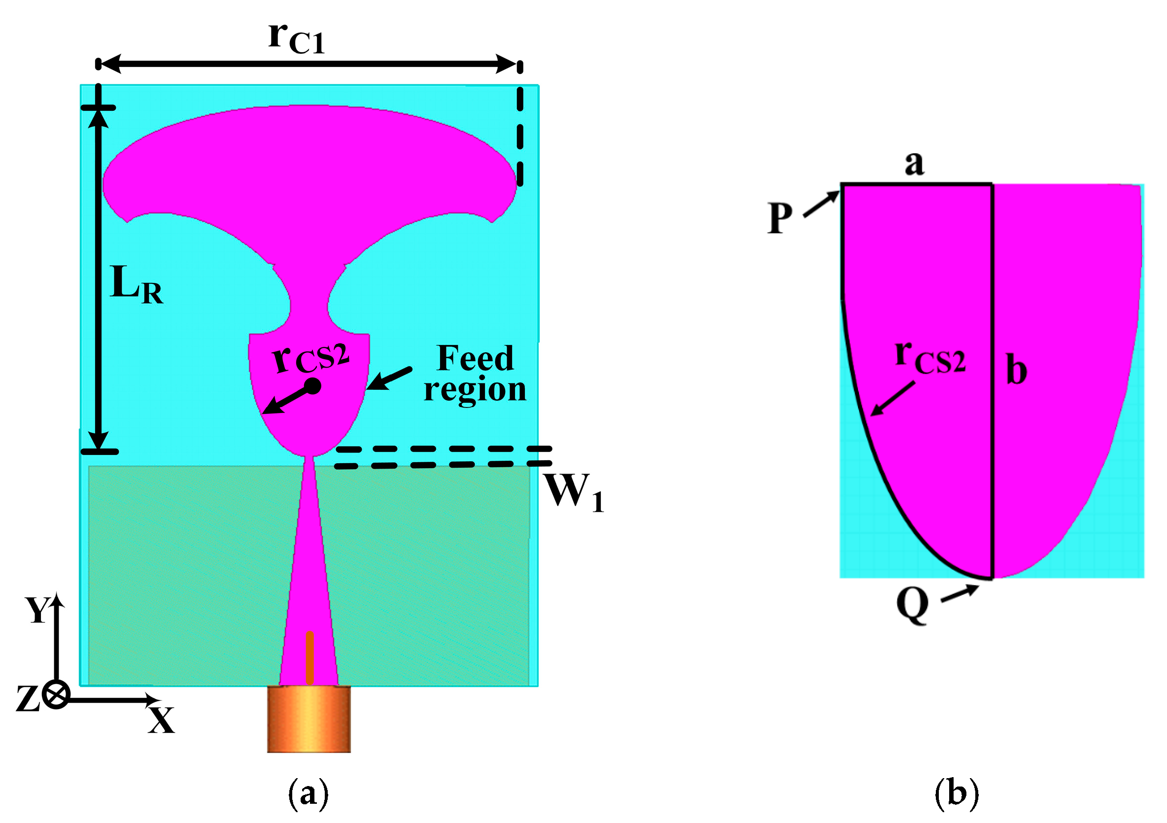
The proposed TSPA geometry and dimensions are illustrated in
Figure 1a and detailed in
Table 1. The overall antenna size measures (21 × 15.5) mm
2, where the partial ground plane spans (15.5 × 7.7) mm
2, which is printed on a 0.508 mm thick substrate, with a relative permittivity of 2.2 and loss tangent 0.0009. The proposed antenna comprises three key sections: the feed region, tapered feed line, and radiating patch. Enhancements were made to optimize antenna performance for wideband operation. These improvements include a feed region connection, smoothing the current path through a tapered connection between the feed line and the main patch, as seen in
Figure 1a. The triangular tapered feed line in
Figure 1 provides a broader BW.
The tapered feed line and radiating patch contribute to the wideband characteristics of this newly proposed broadband-printed monopole antenna. Specifically, the tapered feed region’s optimization ensures proper 50 Ω impedance matching, reducing incident wave reflections. Additionally, the dimensions of the tapered radiating patch were determined using the formula [
31,
32] to achieve the desired performance characteristics.
Here, L
R represents the height of the planar monopole antenna, while r
CS2 denotes the effective radius of the equivalent cylindrical monopole antenna. The parameter W
1 signifies the optimized feed gap, measured as the difference between L
f1 and L
PGP, set to W
1 = 0.3 mm. In contrast to planar monopole antennas, the printed configuration incorporates a dielectric layer on one side of the monopole. The presence of dielectric material results in a decrease in the lower band edge frequency. Consequently, a more suitable equation for determining the lower band edge frequency is provided as follows:
In this context, the value of k = 1.18 has been selected based on empirical considerations for a dielectric layer possessing a dielectric constant ε
r = 2.2. The effective radius of the cylindrical monopole antenna is determined by the following expression:
The area of the semi-ellipse monopole radiating patch is denoted by r
C1. This curved design significantly contributes to achieving excellent frequency matching across an ultra-broadband spectrum. Parameters W
f0 and W
f1 in the triangular tapered feed line are independent of the resonant frequency and are determined using an iterative approach.
Figure 1b visually represents the exponential taper profile characterizing the tapered feed region, defined by parameters like r
CS2 (radius of feed region) and specific points P and Q. The mathematical representation of this exponential curve for the feed region is detailed in Equation (4).
where Y = 0.5 b and X = a.
Therefore, utilizing the mathematical expression provided earlier, we can derive the radius of the feed region. Z
L represents the antenna load impedance, while Z
0 stands for the characteristic impedance of the feed line. The equation detailing the impedance function of the triangular tapered feed line is derived from [
32,
33].
2.1. Impedance Function for the Triangular Tapered Feedline
The triangular taper, as illustrated in
Figure 2e, between W
f0 and W
f1 across length L
f1 is critical for achieving a smooth, wideband transition in characteristic impedance, which minimizes reflection across the operational frequency range. The feedline is a linearly tapered microstrip line whose characteristic impedance, Zc (z), varies continuously along its length, L
taper (which corresponds to L
f1 in the design).
2.1.1. Linear Width Function
The width of the microstrip line, W(z), changes linearly from the start width W
f0 to the end width W
f1 over the taper length L
f1. If z is the distance along the taper, starting at z = 0, the width function is:
2.1.2. Characteristic Impedance Function
The characteristic impedance Zc (z) at any point z is determined by the instantaneous width W(z) and the physical properties of the substrate (height
and relative permittivity ℇr). We employ the well-established empirical equations for the characteristic impedance of a microstrip line, Z
microstrip (W, h, ℇr), to define Zc (z):
For typical microstrip structures, the characteristic impedance is often calculated using closed form expressions [
34,
35,
36], which relate the line geometry to the effective permittivity ℇr and the impedance Z
C. For illustration, the generalized expression for Zc for a microstrip line is approximated as:
Approximation for wide lines
where
h = hSUB is the substrate thickness;
Z0 = 377 Ω is the characteristic impedance of free space;
(W) is the effective relative permittivity, which itself is a function of the line width W, ℇr, and h. By using a linear taper width function W(z), the resulting impedance Zc (z) provides a smooth, non-refractive gradient, allowing for broad impedance matching between the 50 Ω source and the complex input impedance of the radiator across the entire operational bandwidth.
3. Design Strategy and Performance Results
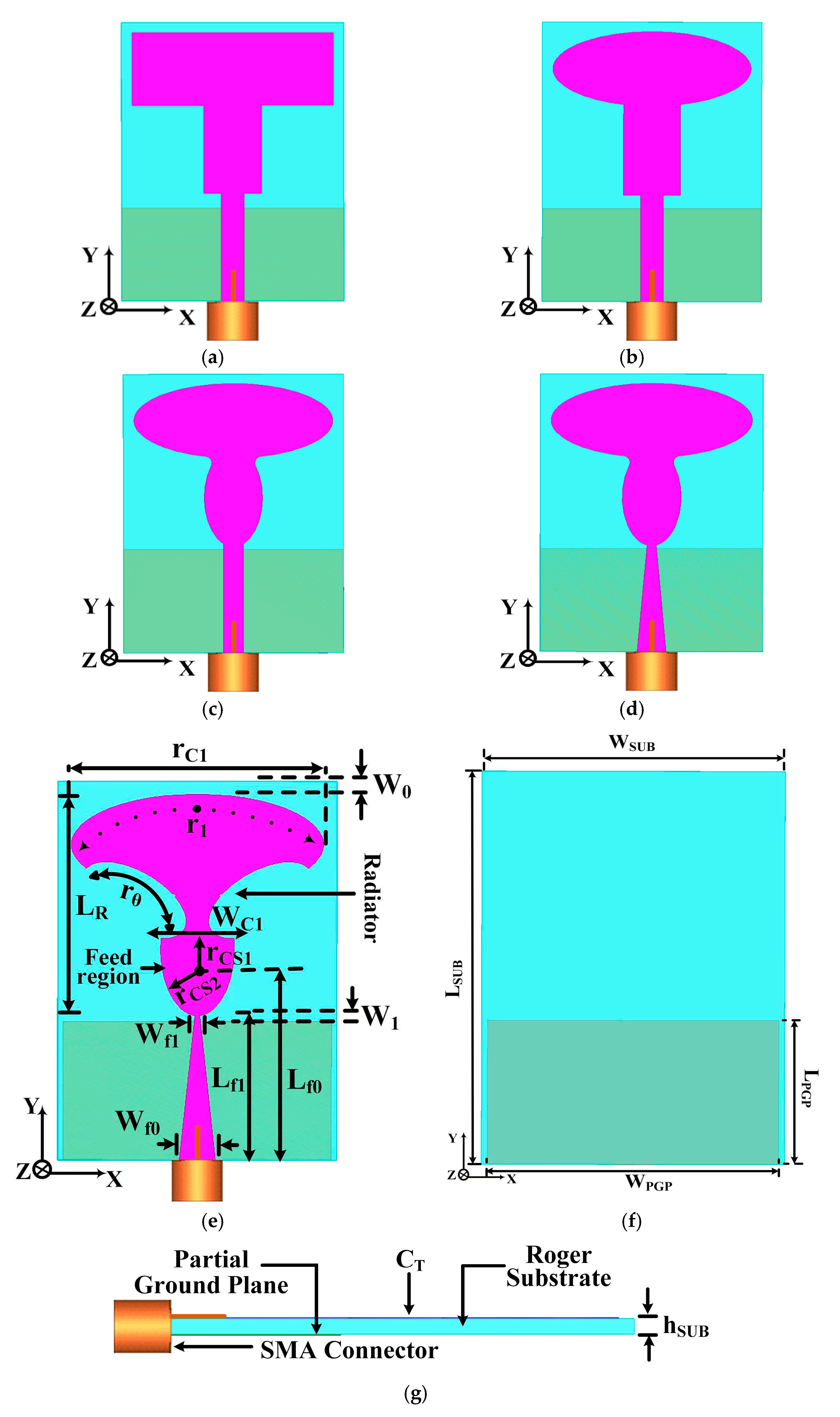
The designed TSPA with a tapered feeding technique is shown in
Figure 2a–g. The proposed model is imprinted on Rogers 5880 substrate with a relative permittivity of 2.2, a loss tangent of 0.0009, and a thickness of 0.508 mm. The substrate dimension is L
SUB × W
SUB with a miniaturized length of 1.05λ
0 × 0.775λ
0, where L
SUB = 21 mm and W
SUB = 15.5 mm. The antenna elements are made of conducting copper material (CCM) with a value of 35 μm. The proposed antenna structure consists of a trowel-shaped patch, an elliptical stub, a tapered feed line, and a partial ground plane. The feed region of the cylindrical stub increases up to the upper width is W
C1 = 4.04 mm, and it is elliptical and decreases at W
f1. For the optimum matching of the feedline, linear decrease is required. The width of the tapered feed line corresponds to W
f0 = 2 mm and is linearly decreased up to W
f1 = 0.26 mm, where the length of the feed line L
f1 = 8.05 mm is fixed. The geometry of the ground plane is important in achieving the lowest resonance frequency and a wide BW, which depends on the longest current path followed. Therefore, the standard partial ground has been set at the optimized values of W
1 and L
PGP variables.
Moreover, the design process for the TSPA is illustrated in
Figure 2a–d.
Figure 2a introduces a basic shape of antenna with a rectangular-shaped radiator and a partial ground plane, fed through a 50 Ω strip feed line. Simulations were conducted; the impedance matching performance is illustrated in
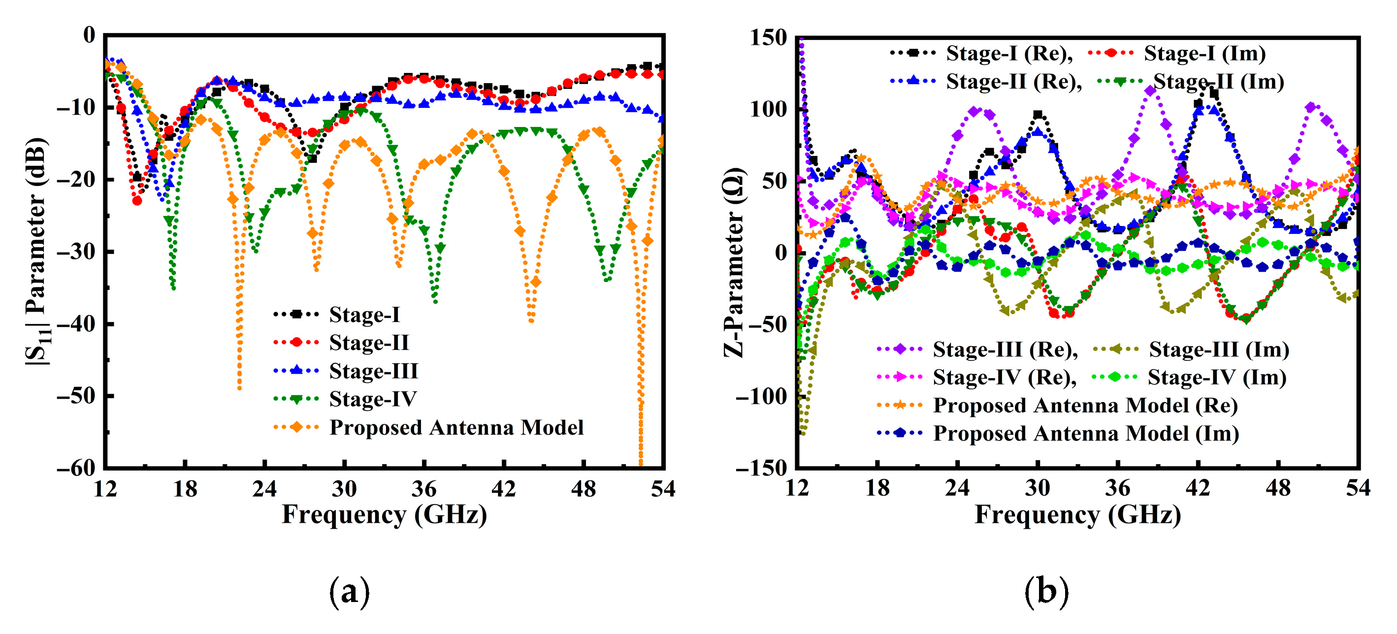
Figure 3a,b. Analysis of
Figure 3a reveals that antenna stage I exhibits significantly degraded matching performance. In the second stage (
Figure 2b), the radiator is modified to an elliptical shape. However,
Figure 3a indicates that the return loss |S
11| remains suboptimal for the considered partial ground plane, feedline, and elliptical radiator. A fillet operation is performed on the top and bottom edges of the modified cylindrical stub and a semi-elliptical radiator, as depicted in
Figure 2c. This alteration resulted in the antenna achieving a good impedance bandwidth at 10 dB return loss. However, it needs further modification in the antenna design to achieve more optimal performance results.
Moreover, the resonance frequency was found to be directly influenced by the longest current path. To improve the input impedance matching and achieve optimal wideband performance, the initial rectangular feedline was modified to a tapered feedline, as illustrated in
Figure 2d. We evaluated this alteration by analyzing the reflection coefficient, S
11 parameter, as shown in
Figure 3a.
The simulated results for Stage IV depicted in
Figure 2d demonstrate a significant improvement in the matching performance compared to antenna stages I, II, and III in
Figure 2a–c. Specifically, the Stage IV design shows deeper and broader reflection coefficient performance. However, a comprehensive analysis of the S
11 parameter reveals that not all targeted frequencies satisfy the critical operational requirement of |S
11| < −10 dB. Achieving this ideal, high-efficiency matching, particularly across the upper end of the operational band and at high-frequency resonance, poses a considerable challenge. Consequently, to fully optimize the wideband input impedance and ensure the maximum possible bandwidth, additional minor adjustments were made to the overall dimensions of the antenna structure, as detailed in
Figure 2e. The symmetrical arc-shaped cavity angle at the radiator r
θ = 59.5° was introduced, along with modifications to the values of partial ground plane width W
PGP = 14.9 mm. For optimal matching performance, the rectangular 50 Ω tapered feedline is transformed into a triangular tapered feedline, as illustrated in
Figure 2e. The simulated results of the proposed structure are presented in
Figure 3a.
The TSPA design, incorporating a tapered feed, partial ground plane, and trowel-shaped patch, demonstrates optimal matching performance with a low cut-off frequency of 15 GHz. Furthermore, the proposed antenna possesses an overall small dimension of 1.05λ
0 × 0.775λ
0 × 0.0254λ
0, and the optimal value geometry of the parametric configuration of the developed antenna is given in
Table 1.
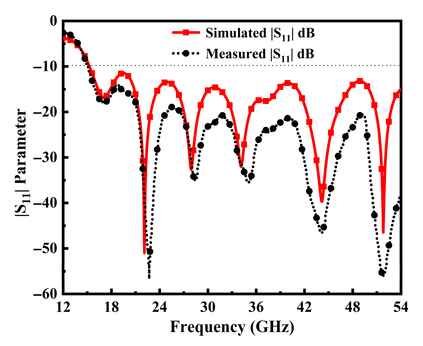
Moreover, the performance of the antenna is significantly influenced by the elliptic tuning stubs, tapered feedline, and partial ground plane. Consequently, the antenna achieves a broad impedance BW, enhanced high gain, and good matching over an extensive frequency range. The performance of the antenna prototypes, as indicated by the |S
11| parameter, is illustrated in
Figure 3a. Notably, the proposed antenna structure attains perfect matching with a fractional BW of 113.05% (red curve) from 15–54 GHz. In
Figure 3b, the simulated variation of the real and imaginary parts of the z-parameter is presented, demonstrating that the input impedance of the antenna port is matched with a z value of 50 Ω at the operable resonances.
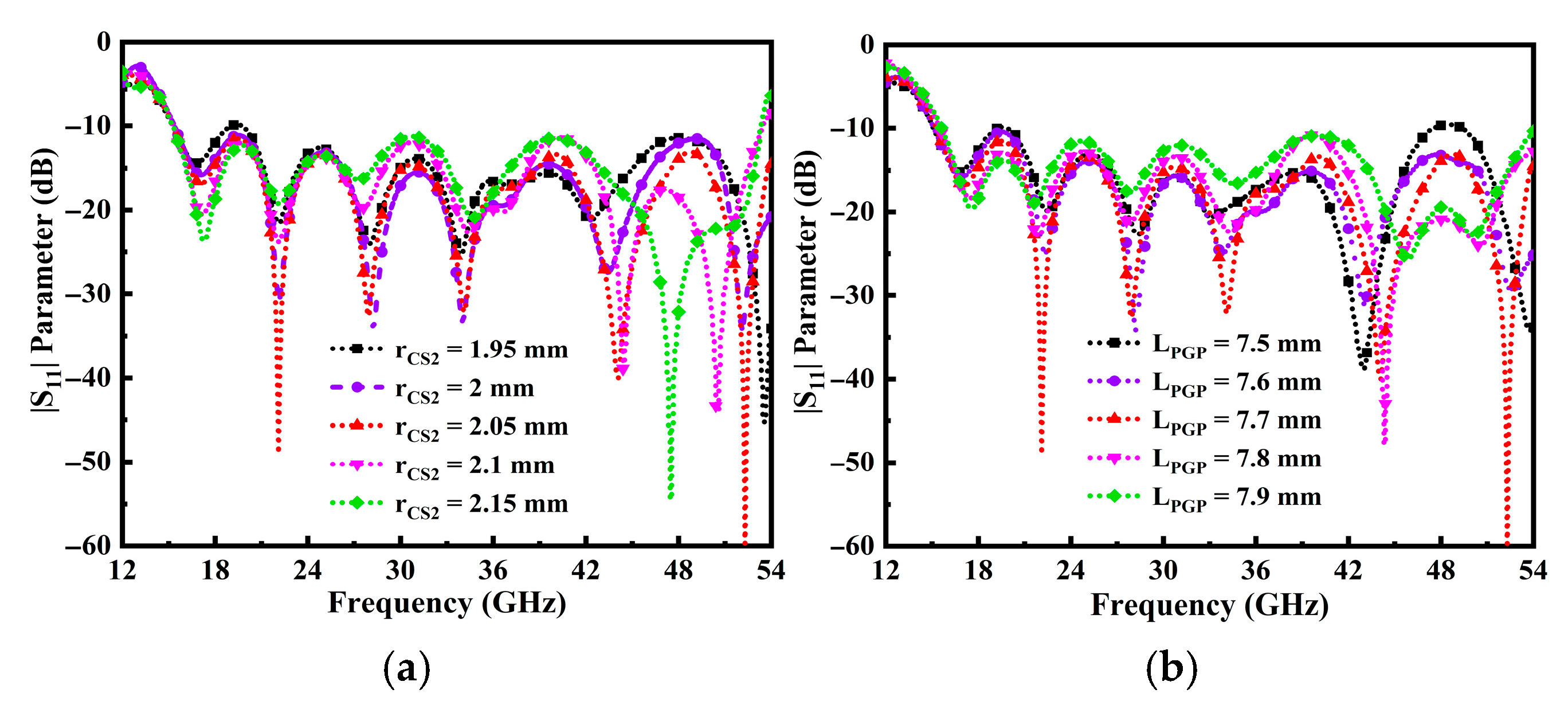
As stated before, the size of the cylindrical loaded cavity stub (r
CS2) influences the proposed antenna impedance matching performance features.
Figure 4a demonstrates the impact of reducing and increasing the cylindrical stub size at the associated point. Additionally,
Figure 2e visually represents the positioning of narrower and wider cylindrical stubs relative to the center of the radiator. It can be analyzed that when the r
CS2 is 2.05 mm, perfect impedance matching and inclusive impedance BW are achieved. Likewise, it is noticeable that the impedance performance at the higher resonance point does not align when r
CS2 values are in the later stage.
Figure 4b clarifies the impact of the partial ground plane length (L
PGP) across the frequency range.
Notably, with a maximum value of LPGP set at 7.9 mm, the antenna achieves perfect impedance matching and a broad impedance BW, observed at the minimum value of 60 dB return loss. In addition, lower values of LPGP strongly affect the impedance BW. From the above analysis, it can be concluded that the rCS2 and LPGP have a great influence on the impedance matching and BW in the operable frequency span.
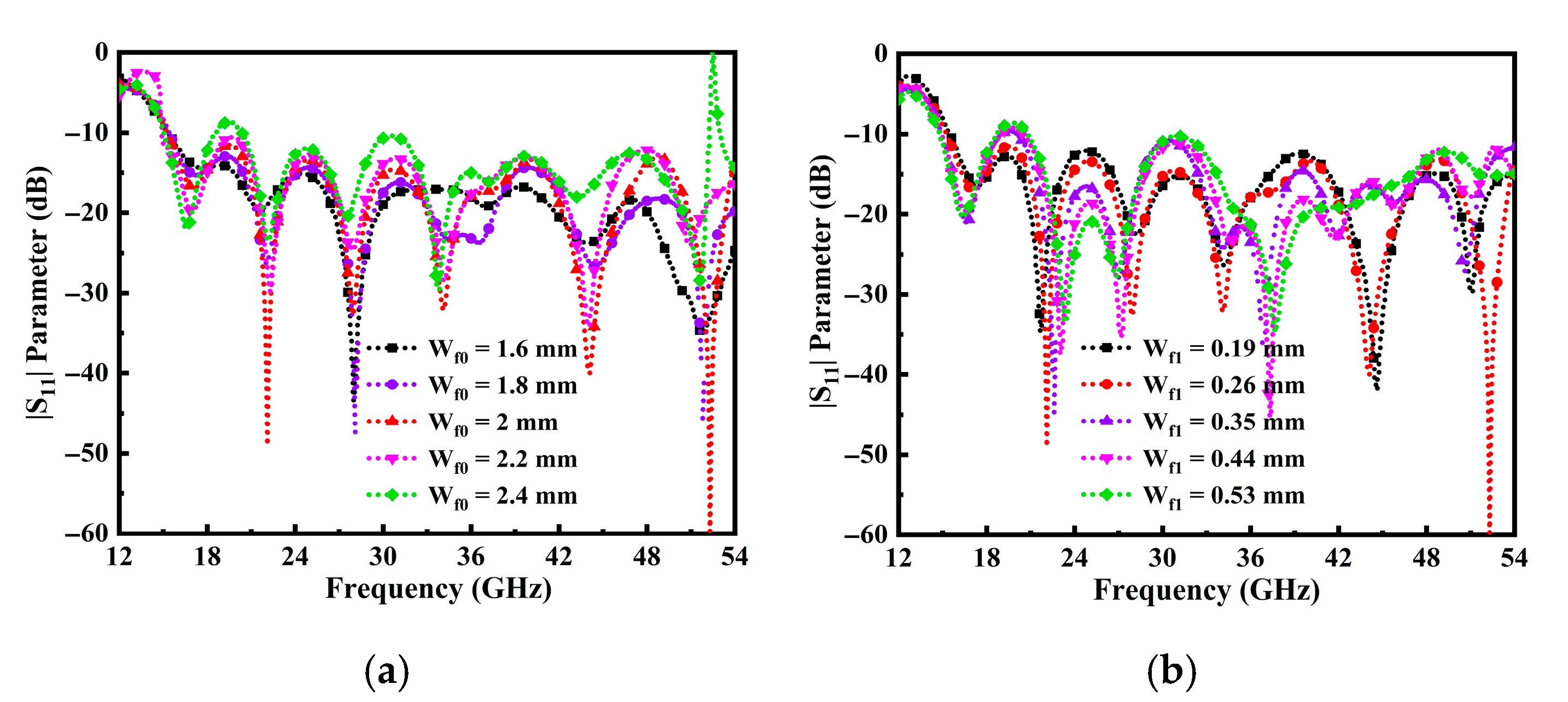
Moreover, the parametric study was concluded with the excitation of a wider tapered feedline (W
f0) section connected to a narrower feed (W
f1) section linked with a cavity stub. The aim was to achieve the optimal configuration for extending the BW of the TSPA. The width of the tapered section and the partial ground plane were systematically optimized by exploring various positions and assorted distances from the center of the radiator to attain a broader BW and improve impedance matching. From
Figure 5a, it can be observed that when the W
f0 is 2 mm, the wider BW is achieved. Furthermore, the impact on the W
f1 narrower tapered feedline section is observed to be the perfect matching at the optimum value of 0.26 mm, as shown in
Figure 5b.
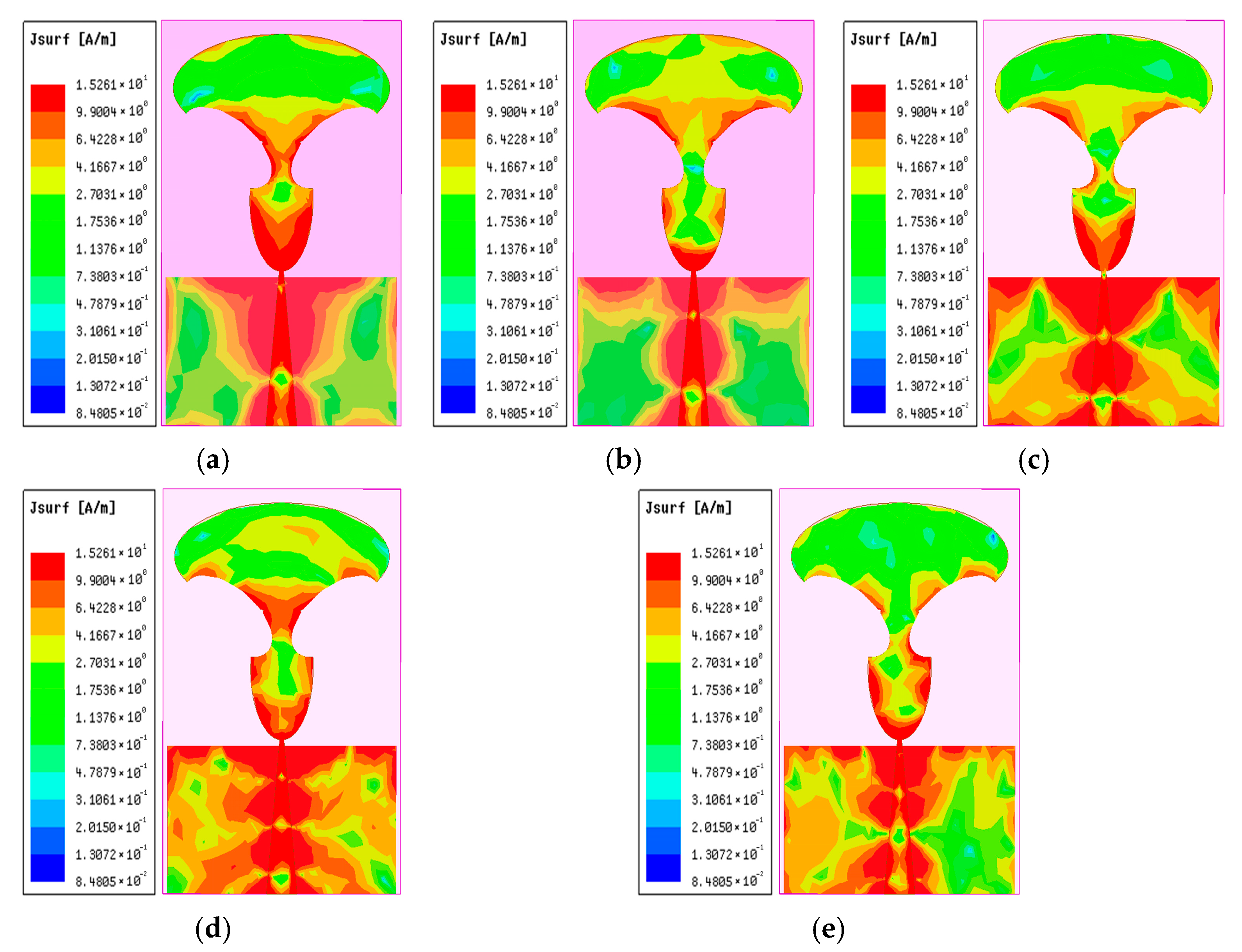
Figure 6a–e portrays the current distribution on the radiator’s surface corresponding to five resonance points at 22.1 GHz, 27.9 GHz, 34.14 GHz, 44.2 GHz, and 51.8 GHz. It can be seen that the proposed antenna exhibits a strong distribution of current on the feedline, the edges of the radiator, and the edges of the partial ground plane. At 22.1 GHz, peak current densities localize near the feed region and tapered edges, confirming efficient excitation of the fundamental mode. As frequency increases to 27.9 GHz and 34.14 GHz, the current spreads asymmetrically along the radiator’s flared sections.
At higher frequencies of 44.2 GHz and 51.8 GHz, the surface current distribution concentrates primarily around the radiator, exhibiting progressive phase variations that help suppress parasitic coupling. A noticeable decay in current magnitude from the feed point toward the edges is observed, indicating effective radiation and minimized ohmic losses. This behavior confirms well-controlled current flow and supports the antenna’s broadband characteristics. The repeatable current patterns across frequencies further validate the multi-resonant nature of the design. Moreover, a strong and consistent current flow within the operational band highlights the antenna’s efficient excitation and structural simplicity.
6. Conclusions and Future Perspectives
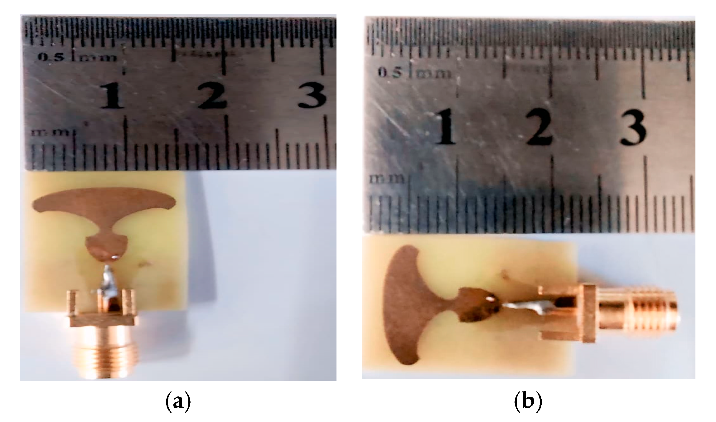
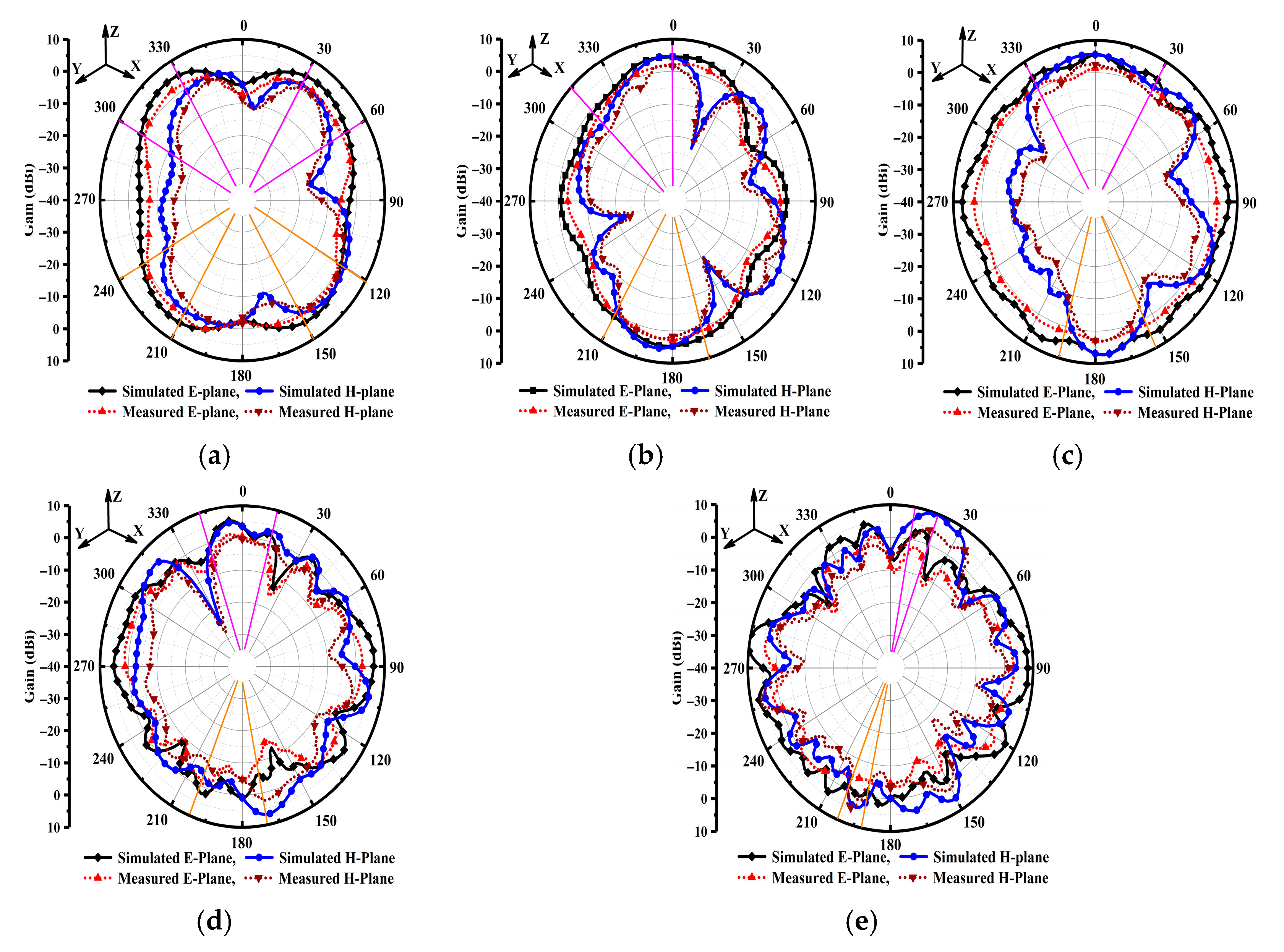
In this work, a novel compact low-cost, high-performance TSPA for 6G next-generation wireless communication systems is presented. Through meticulous design and analysis, the TSPA demonstrates exceptional broadband characteristics with stable resonances at 22.1, 27.9, 34.1, 44.2, and 51.8 GHz. The key performance metrics, including impedance bandwidth, surface current distribution, peak realized gain, radiation efficiency, and radiation patterns, were investigated through simulations and experimental measurements, revealing remarkable agreement between theoretical predictions and practical implementations. The antenna achieved a high gain of 9.67 dBi and maintained radiation efficiency above 90% across the entire operating band, with consistent radiation patterns suitable for diverse modern 6G next-generation wireless communication systems. The TSPA geometry effectively minimizes losses and suppresses unwanted harmonics, while the compact and low-profile design ensures compatibility with modern integrated systems. These attributes, combined with the antenna’s cost-effective fabrication process, make it a compelling candidate for next-generation 6G networks, IoT devices, and phased-array systems. Future work could explore the integration of this antenna into MIMO configurations and its adaptation for reconfigurable frequency operation. The results presented in this study underscore the potential of innovative planar antenna designs to meet the escalating demands of high-speed wireless communication, paving the way for further advancements in millimeter wave wireless communication technology. Moreover, we plan to address the integration of the TSPA element into large-scale, high-density phased arrays. Specifically, future work may focus on mitigating the effects of scan blindness and pattern degradation at wide scan angles, which become critical issues when tightly packing wideband elements. Furthermore, we intend to investigate methods for thermal management within the array, as the cumulative power dissipation from numerous high-efficiency elements operating continuously at mmWave frequencies can impact the stability and longevity of the RO5880 substrate and the associated active circuitry. Addressing these challenges is essential for transitioning the TSPA from a high-performance singular element to a viable, robust component for commercial, massive-MIMO and beam forming applications.
