Article

Enhancing the Output Performance of Fiber-TENG Through Graphite Doping and Its Application in Human Motion Sensing

Department of Mechanical Engineering, National Cheng Kung University, Tainan 701, Taiwan
*
Author to whom correspondence should be addressed.
Sensors 2025, 25(20), 6409; https://doi.org/10.3390/s25206409
Submission received: 5 September 2025 / Revised: 15 October 2025 / Accepted: 15 October 2025 / Published: 17 October 2025

Abstract

Triboelectric nanogenerators (TENG) are mechanical energy harvesters characterized by high sensitivity and simple structure and are currently being widely developed for use in human body motion sensing. Among them, fiber-based TENGs (FTENG) are particularly suitable for wearable human motion sensors due to their unique structure, which offers flexibility, high durability, and comfort. However, studies involving doping to further modify the electrical output characteristics of FTENGs are very limited. Here, we propose an innovative approach that combines graphite (GP) doping with fiber-based TENG fabrication, successfully developing a graphite-doped polyester fiber-based TENG (GP@PET-TENG). Proper graphite doping can increase the amount of transferred charge and thus improve the output electrical performance of TENG, but this method has rarely been explored in FTENG. With the incorporation of 3%wt graphite, the open-circuit voltage of the GP@PET-TENG increased from 103.3 V to 202.1 V, and the short-circuit current increased from 60.7 μA to 105.1 μA, compared to the pure polyester fiber based TENG (PET-TENG). The device achieved a maximum output power of 4.15 mW (2.59 W/m2), demonstrates the capability to charge various capacitors, and successfully lit up 200 LEDs. By attaching the GP@PET tribo-layer to human skin, a single-electrode mode TENG can be formed, which captures the subject’s motion signals through skin contact and separation, converting them into voltage outputs. In fist-clenching and wrist-bending tests, motion-induced voltage signals up to 0.6 V were recorded, demonstrating the potential applications in rehabilitation assistance and mechanical control.

1. Introduction

With recent advancements in semiconductor technology reducing critical dimensions and costs, wearable sensors have become smaller and more widespread. This has enabled the real-time capture and recording of previously hard-to-measure human motion signals and data, such as respiratory rate and blood oxygen levels. Such data can be used for health monitoring, exercise tracking, rehabilitation, medical applications, and even mechanical control [1,2,3]. For example, human body motion sensors record the distribution of force exerted by human steps for rehabilitation purposes or transmit motion data to a computer for data control in real-time [4,5]. Traditional human body motion sensors often use capacitive and resistive devices that require an external energy supply [6,7]. As the precision of human motion measurement increases, more sensors are required in the system, leading to higher energy consumption. Besides the energy issue, current power storage devices cannot sustain such sensor systems. Therefore, finding an alternative to traditional mechanical sensing devices is crucial for developing wearable sensors [8,9,10]. Mechanical energy harvesters, which convert mechanical energy into electrical signals and power, such as electro-mechanical generators and piezoelectric nanogenerators, are considered future substitutes for sensors [11]. TENG, known for its high mechanical sensitivity, material flexibility, and lightweight properties, is particularly viewed as an essential technology to replace traditional wearable sensors [12]. TENG operates through four mechanisms [13], with vertical contact-separation [14,15] and single-electrode modes [16] being widely used as mechanical sensors due to their strong correlation between output voltage and applied force, and high linearity [17,18]. FTENGs are a type of TENG that incorporate fiber structures or fiber-based into polymer-based materials to enhance both the mechanical robustness and electrical output performance of the device. FTENGs are commonly fabricated by either electrospinning polymers such as polyvinylidene fluoride (PVDF) into fibers [19] for textile formation or embedding commercial fiber fabrics such as cotton into polymer materials [20]. Owing to their lightweight nature, high durability, stretchability, and flexibility, they are considered one of the most promising TENG types for the development of wearable sensors [21,22,23] and have been applied in human motion sensing [24,25]. Fabricating tribo-layers of FTENGs by coating polymer materials onto fiber provides benefits of rapid, low-cost processing [26,27,28]. However, further enhancement of their electrical output remains challenging. Material doping presents an alternative strategy by modifying the electrical properties of the tribo-layers [29,30,31,32]. For instance, conductive material doping has been reported to reduce charge transfer resistance and enhance both transferred and induced charge density [33,34]. Compared with other conductive dopants such as CNTs [35] and metallic materials [36], micron-sized graphite particles offer advantages of low cost, easy availability, and low environmental impact; yet this approach has rarely been explored in FTENGs.
In this study, we propose an innovative method to enhance FTENG performance by doping PDMS with varying concentrations of micron-sized graphite and coating it onto polyester fabric to fabricate GP@PET-TENGs. GP@PET-TENG doped with 3%wt graphite exhibited the highest output performance, with an open-circuit voltage of 202.1 V and a short-circuit current of 105.1 μA which representing 1.96 times and 1.73 times increase, respectively, compared to the pure PET-TENG (103.3 V and 60.7 μA). GP@PET-TENG achieved a maximum output power of 4.15 mW (2.59 W/m2) at a load resistance of 1 MΩ and which is enable to charge various capacities from 0.33 μF to 2.2 μF over 1.0 V and light up to 200 LEDs at once. By attaching the GP@PET tribo-layer to human skin, it forms a single-electrode mode TENG capable of effectively capturing motion signals generated from bending at the third finger joint and wrist. These mechanical movements are converted into electrical signals with a maximum output voltage of 0.6 V. In the future, with the integration of signal processing circuits and electronic control modules, these signals can be further converted into meaningful human motion data and control signals for practical applications.

2. Experimental Procedures

2.1. Fabrication of GP@PET-TENG

GP@PET-TENG is composed of an aluminum electrode and graphite-doped PDMS coated PET fibers. The aluminum electrode is commercially available low-purity aluminum, ready for use upon purchase. This section focuses on the fabrication process of the graphite-doped PDMS-coated PET fibers. To create a sufficient PDMS thickness, a PMMA mold with a 50 × 50 × 5 mm3 dimension was used. A 1 mm deep groove was made in the PMMA using a CO2 laser, creating a 40 × 40 mm2 recess, as shown in Figure 1a. Next, 1~5%wt micron-sized graphite particles were added to the PDMS fluid mixed with a curing agent. This fluid was then poured into the PMMA mold, as depicted in Figure 1b. The 50 × 50 mm2 PET, pre-attached to a 40 × 40 mm2 nickel-coated cotton cloth electrode, was submerged into the PDMS fluid, allowing it to infiltrate and coat the PET fiber structure, as shown in Figure 1c. The sample and mold were placed in a vacuum chamber for 10 min to remove air bubbles from the PDMS and PET, as shown in Figure 1d. The sample and mold were then placed in an oven at 70 °C for 1 h to cure the PDMS, as shown in Figure 1e. Finally, the sample was demolded, and excess PDMS was trimmed to obtain the graphite-doped Polyester fiber based tribo-layers (GP@PET tribo-layers), as shown in Figure 1f. Figure 1g,h present the front and back sides of photographs of the fabricated GP@PET tribo-layers, respectively. The yellow reflective strip underneath corresponds to the copper tape, which functions as the lead for the nickel-coated fabric electrode in subsequent electrical connections. The green tape is applied to mechanically protect the copper tape during operation. By replacing the curing agent with pure PDMS in the same fabrication process, polyester fiber-based tribo-layers (PET tribo-layers) without graphite doping can be obtained.

2.2. The Experiment and Measurement of Various PET-TENG

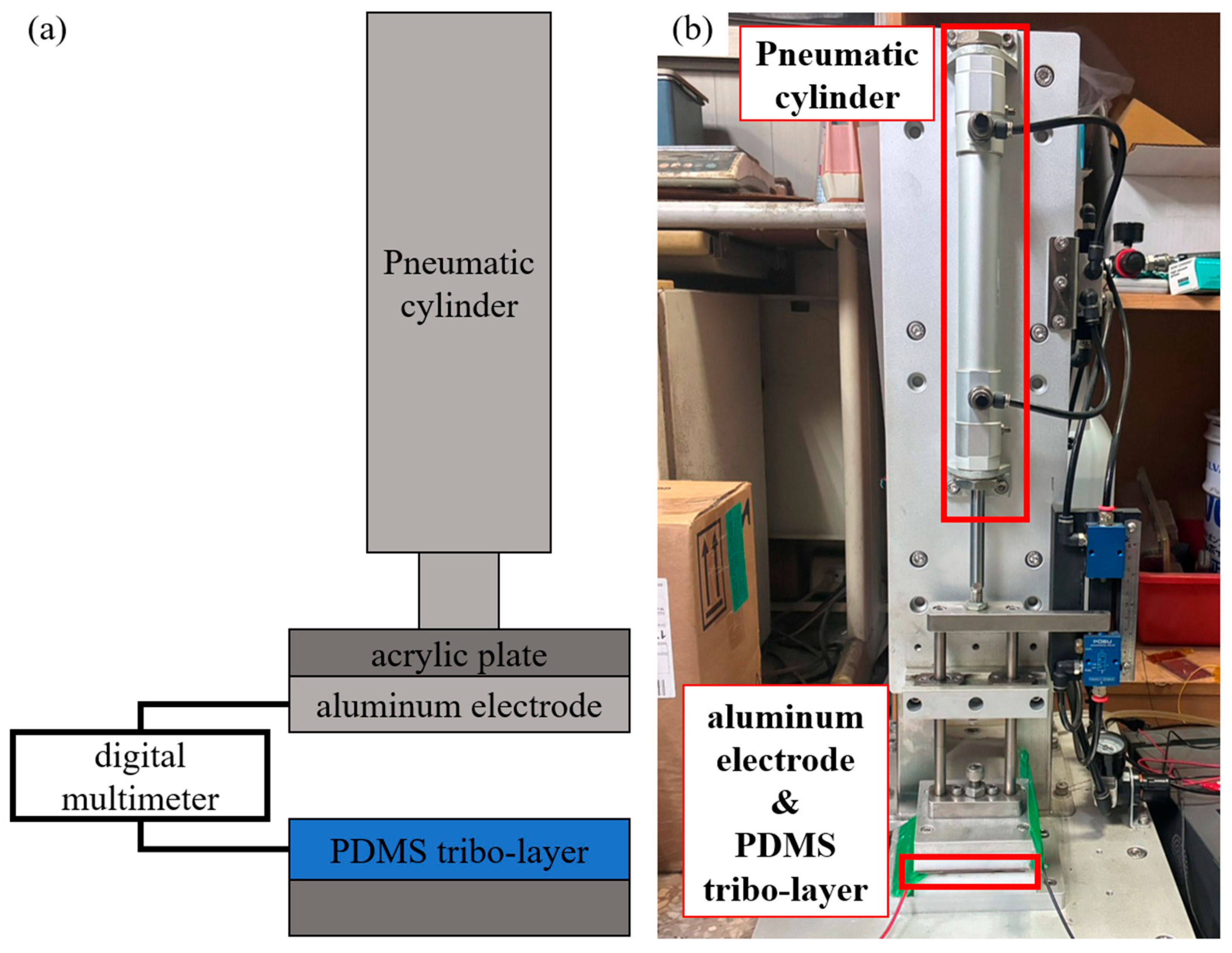
To evaluate and compare the output performance of various PET-TENGs, a digital multimeter (DMM6500 6.5 Digit Multimeter, Keithley, Solon, OH, USA) was used to measure the electrical output signals, while a pneumatic actuation platform provided a stable and repeatable external force. On the platform, the PDMS tribo-layer of the TENG was fixed onto the stationary base of the pneumatic cylinder (RHCL25-100, SMC, Chiyoda, Tokyo, Japan) using an acrylic plate, and the aluminum electrode, serving as the other tribo-layer, was mounted on the moving shaft. The measurements were conducted under a stroke length of 5 mm, with a periodic force of 50 N at a frequency of 7 Hz, as shown in Figure 2a,b. The measurements in this experiment were all conducted under an environment with a temperature of 25 °C and a humidity of 62%.

3. Results and Discussion

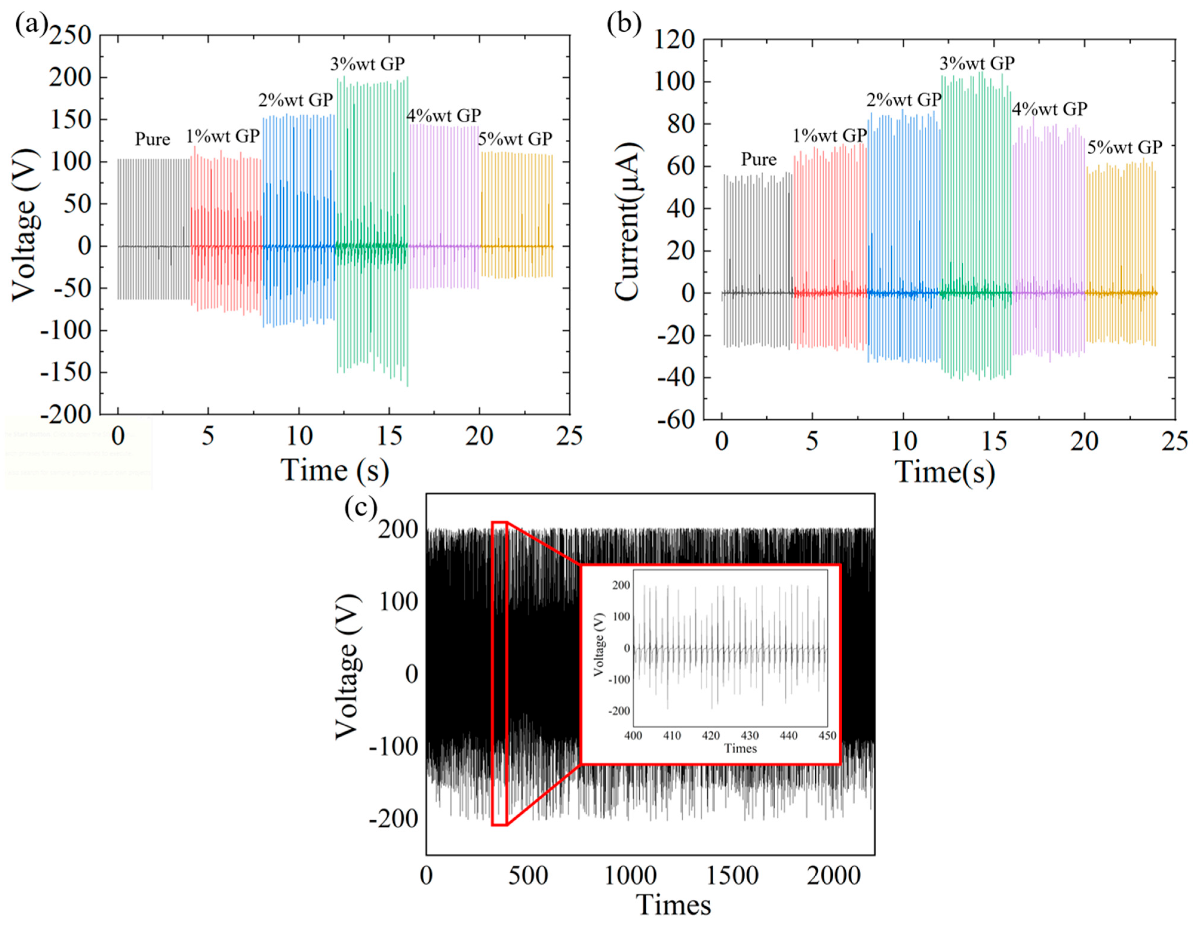
In TENG research, the open-circuit voltage (Voc) and short-circuit current (Isc) are commonly used as key indicators to evaluate output performance. To investigate the effect of different graphite doping concentrations on PET-TENGs, we first measured the Voc and Isc of the undoped PET-TENG (pure) as well as GP@PET-TENGs doped with various graphite weight percentages (1%wt, 2%wt, 3%wt, 4%wt, and 5%wt). The measured Voc values were 103.3 V, 118.8 V, 157.4 V, 202.1 V, 145.5 V, and 113.0 V, respectively, while the corresponding Isc values were 60.7 μA, 71.1 μA, 87.2 μA, 105.1 μA, 83.7 μA, and 64.3 μA, as shown in Figure 3a,b. These results indicate that the PET-TENG with 3%wt graphite doping exhibited the highest output performance in both Voc and Isc, representing improvements of 196% and 173%, respectively, compared to the undoped PET-TENG. Additionally, by testing the Voc of the 3%wt GP@PET-TENG over more than 2000 cycles of contact–separation, it was observed that the output did not show any significant degradation. This demonstrates that the 3%wt GP@PET-TENG has a durability exceeding 2000 cycles, and during this period, neither the PDMS film nor the graphite particles suffered damage, leakage, or failure, as shown in Figure 3c.
Given that the composite thin-film TENG structure belongs to the conductor–dielectric contact mode [37], this phenomenon can be explained using the V–Q–X relationship [37], which describes the relationship among the output voltage (V), transferred charge (Q), and the separation distance (X) between the two tribo-layers as follows:
V = Q A ε 0 d ε r + x t + σ · x t ε 0
where ε0 represents the vacuum dielectric constant, A is the surface area, εr is the relative dielectric constant of the composite material, d is the thickness of the dielectric layer, and σ is the surface charge density. In the open circuit condition, there is no charge transfer, that is, Q is 0, and the Voc is given by:
V o c = σ · x t ε 0
The VOC is proportional to the triboelectric charge density (σ). Having a higher triboelectric charge density will increase the output voltage.
Under short-circuit conditions, there is no output voltage and the ISC is given by:
I s c = d d t Q s c = d d t A σ · x t d ε r + x t = A σ d ε r d ε r + x t 2   d x d t
In addition, the triboelectric charge density σ is proportional to the dielectric constant (εr),
σ = ε 0 ε r V d
Since the thickness (d), distance (x(t)), and contact area (A) are consistent across different PET-TENG samples, the variations in voltage and current output can be attributed to differences in the charge density (σ) of the tribo-layers. In dielectric tribo-layers, doping with a moderate amount of conductive material can enhance the material’s conductivity, thereby improving the efficiency of charge transfer. However, excessive doping may reduce the dielectric properties of the tribo-layer, weakening its ability to retain electrostatic potential. Therefore, appropriate doping contributes to an increase in both the charge density (σ) and the relative permittivity (εr), ultimately enhancing the output voltage and current of the TENG. In this study, micron-sized graphite particles were incrementally doped into the PDMS film to enhance charge transport efficiency and thereby improve the electrical output performance of the TENG. However, when the graphite doping concentration exceeded 3 wt%, the dielectric properties of the PDMS film were adversely affected, leading to a decline in output performance. A doping ratio of 3 wt% was identified as the optimal threshold, resulting in the best performance in the GP@PET-TENG. This is because when graphite, a conductive material, is doped into the dielectric material PDMS, the graphite reduces the impedance to charge flow within the GP@PDMS tribo-layer for increasing the amount of charge generated during the contact separation process, ultimately reflecting an increase in the open-circuit voltage and short-circuit current. Therefore, doping pure PDMS with graphite leads to improved output electrical performance. However, as the graphite doping concentration increases, exceeding 3 wt%, the relative permittivity of the GP@PDMS tribo-layer decreases significantly. This also reduces the amount of charge that can be generated during contact separation under the same conditions, further reducing the open-circuit voltage and short-circuit current. Increasing the graphite doping concentration at any concentration reduces both the impedance to charge flow within the GP@PDMS tribo-layer and the relative permittivity, but the effects of these two factors vary at different concentrations.
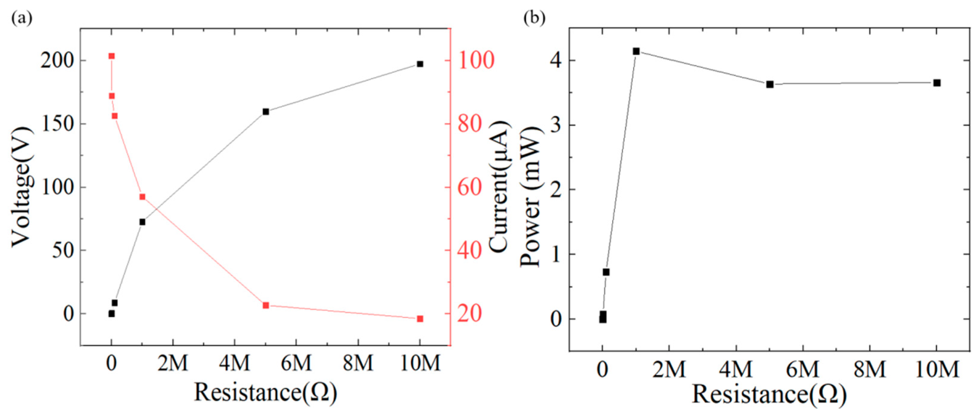
By measuring the output voltage and current of the TENG under different external load of resistances, the maximum output load and electrical performance can be determined with formula P = I × V. The 3%wt GP@PET-TENG achieved its highest output power of 4.15 mW (2.59 W/m2) at an external load of 1 MΩ with 72.66 V and 57.05 μA, as shown in Figure 4a. The output powers at different load resistances were measured as follows: 228.38 nW (142.75 μW/m2) at 1 kΩ, 769 μW (480.63 mW/m2) at 10 kΩ, 728.78 μW (455.49 mW/m2) at 100 kΩ, 3.64 mW (2.28 W/m2) at 5 MΩ, and 3.66 mW (2.29 W/m2) at 10 MΩ, as shown in Figure 4b.
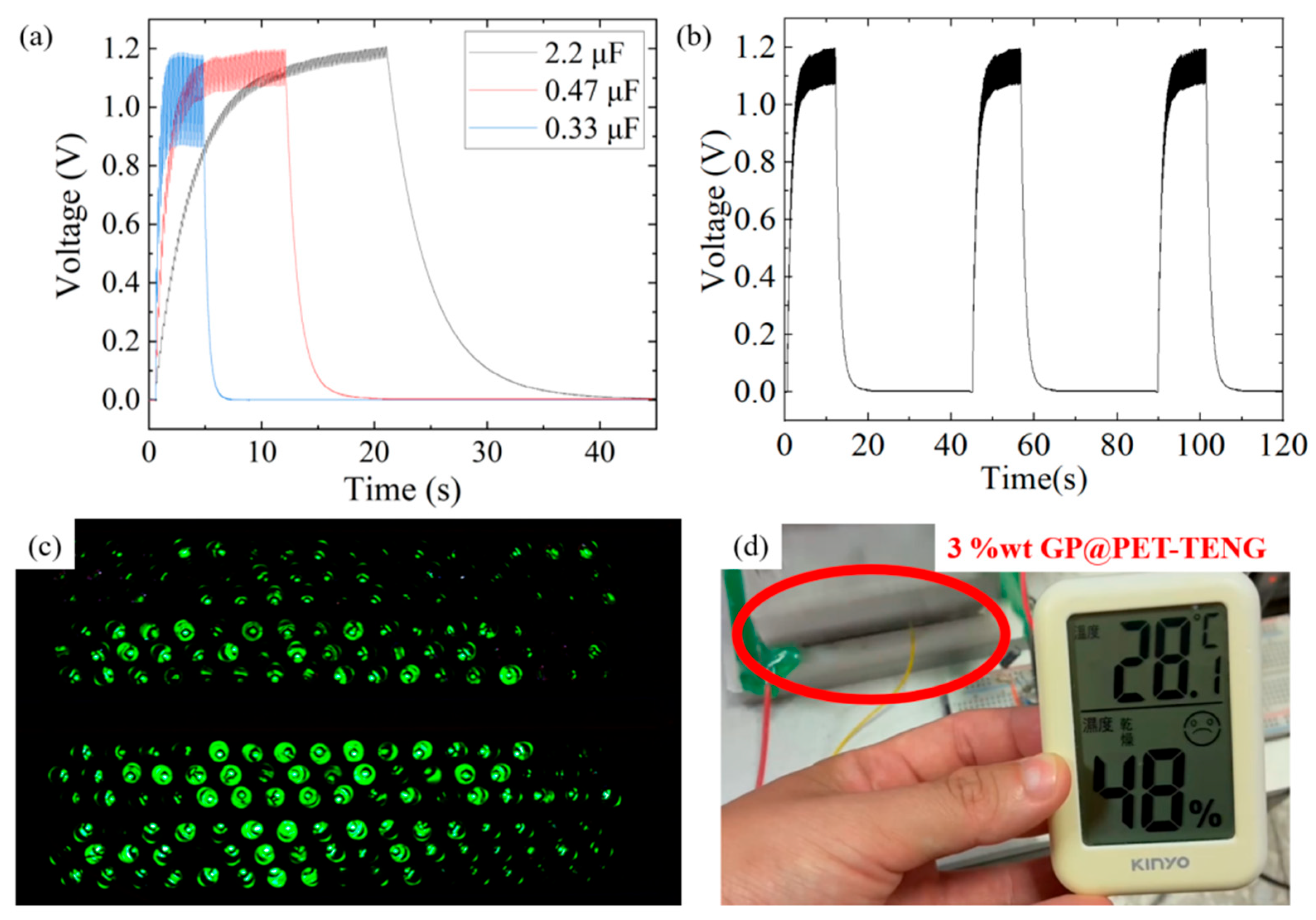
To further evaluate the electrical driving capability of the 3%wt GP@PET-TENG, various capacitors were connected in parallel with a 1 MΩ load resistor via a bridge rectifier and a circuit switch, and then charged/discharged by the 3%wt GP@PET-TENG. The device successfully charged 2.2 μF, 0.47 μF, and 0.33 μF capacitors to stable voltages of 1.2 V, 1.1 V, and 1.0 V within 23 s, 5 s, and 1 s, respectively, as shown in Figure 5a. Due to their higher charge storage capacity, larger capacitors tend to exhibit higher terminal voltages upon full charging. After switching off the circuit, the corresponding discharge times were 18 s, 5 s, and 1 s. This charge–discharge behavior is highly repeatable, as shown in Figure 5b. Additionally, the 3%wt GP@PET-TENG demonstrated the capability to instantaneously light up 200 LEDs with each tapping cycle, as shown in Figure 5c. These results confirm the excellent electrical output and component-driving capability of the 3%wt GP@PET-TENG. In addition, the 3 wt% GP@PET-TENG was connected across a 0.47 μF capacitor and linked to a miniature electronic temperature–humidity sensor. Once the capacitor was fully charged and the voltage stabilized, the 3 wt% GP@PET-TENG successfully powered the sensor, demonstrating its potential for driving small electronic sensing devices, as shown in Figure 5d.
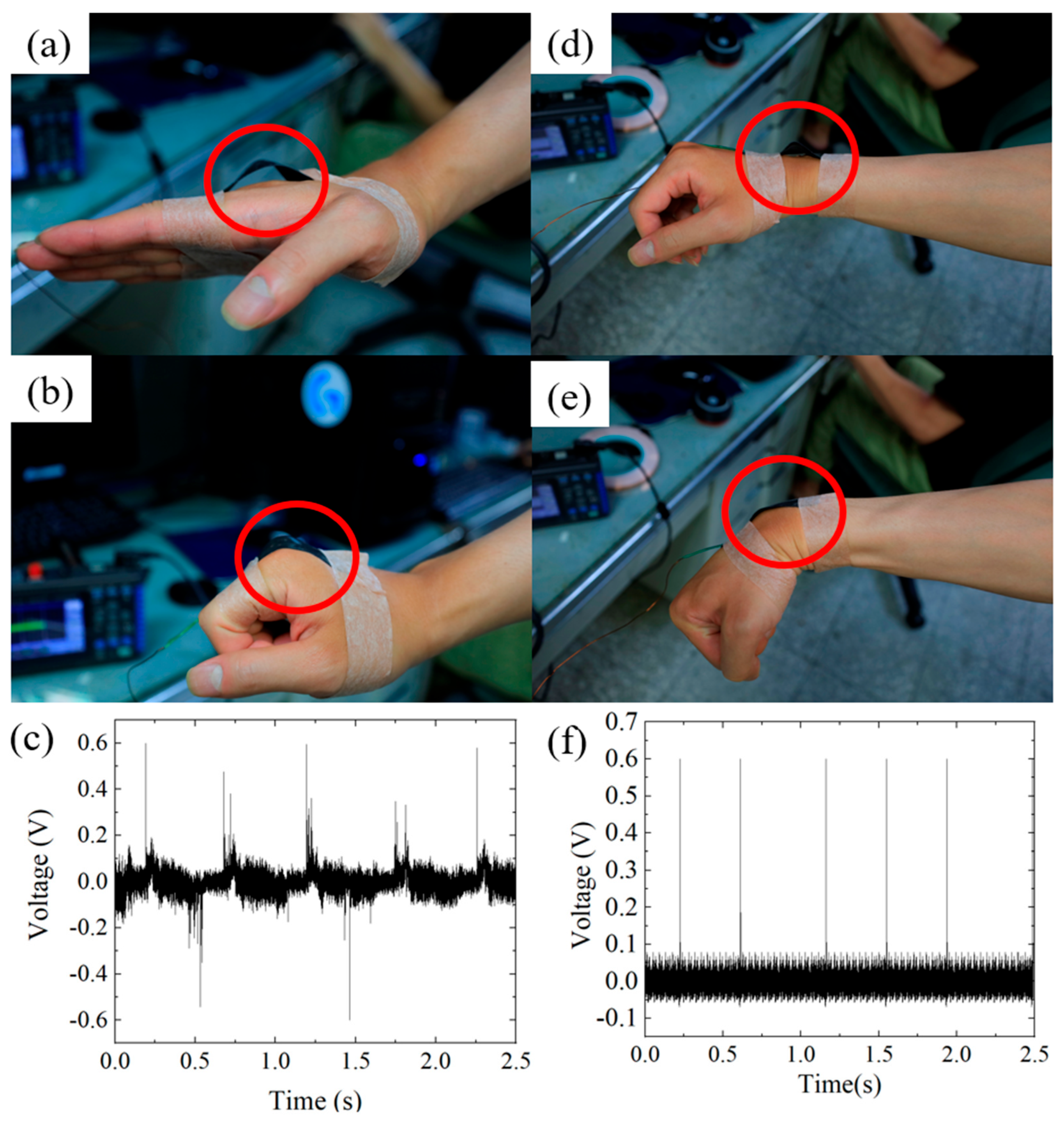
Finally, the 3%wt GP@PET tribo-layer was utilized as a human body motion sensor by attaching it to the skin to detect stretching and contraction during joint bending. Since human skin is a charge-releasing material in the tribo-pair, it can form a single-electrode mode TENG with the 3%wt GP@PET tribo-layer. The sensor was attached to the back of the third knuckle of the finger and the back of the wrist joint, as shown in Figure 6a,d. When the subject clenched their fist or bent their wrist, the tribo-layer made contact with the skin, as shown in Figure 6b,e; when the fist or wrist was straightened, the tribo-layer separated from the skin, completing a contact-separation cycle, as shown in Figure 6a,d. In each bending and straightening motion, the 3%wt GP@PET tribo-layer consistently captured the motion signals, generating electrical outputs of up to 0.6 V for both fist and wrist movements, as shown in Figure 6c,f. When the 3%wt GP@PET tribo-layer is attached to the third knuckle, fist clenching and relaxing cause not only contact-separation cycles with the skin but also induce lateral deformation of the tribo-layer. In comparison, the wrist joint exhibits more stable output signals during flexion and extension. With the integration of electronic control modules and signal processing circuits, these signals can be further utilized as effective inputs for motion monitoring and control applications.

4. Conclusions

To rapidly and cost-effectively enhance the output performance of flexible FTENGs, this study uniquely introduces graphite doping to further improve their electrical output. Among various graphite doping concentrations, the GP@PET-TENG with 3%wt graphite exhibited the highest performance, achieving an open-circuit voltage (Voc) of 202.1 V and a short-circuit current (Isc) of 105.1 μA. It also reached a maximum output power of 4.15 mW (2.59 W/m2) under a 1 MΩ external load. The 3%wt GP@PET-TENG demonstrated the ability to charge a 2.2 μF capacitor to 1.2 V within 23 s and discharge it within 18 s, and successfully powered 200 LEDs with a single tap. When the 3%wt GP@PET tribo-layer was attached to the back of a subject’s third finger joint and wrist, it formed a single-electrode mode TENG capable of capturing motion signals during finger and wrist bending. These signals were converted into output voltages up to 0.6 V. By integrating this TENG with signal processing circuits and control units, human motion signals can be effectively captured and utilized for motion control and real-time monitoring applications.

Author Contributions

C.-K.C. proposed the original idea; Y.-J.H. worked on the conceptualization, organization, discussion and the draft writing; Y.-J.H. and J.-I.C. made the experiments, figure drawing, information survey. All authors have read and agreed to the published version of the manuscript.

Funding

This research was partially supported by the National Science and Technology Council (NSTC), Taiwan, under grant number NSTC 113-2221-E-006-099-MY3.

Institutional Review Board Statement

Not applicable.

Informed Consent Statement

Not applicable.

Data Availability Statement

Data are presented in the coauthors’ research results and schematic drawings available on request.

Conflicts of Interest

The authors declare no conflicts of interest.

References

  1. Porciuncula, F.; Roto, A.V.; Kumar, D.; Davis, I.; Roy, S.; Walsh, C.J.; Awad, L.N. Wearable movement sensors for rehabilitation: A focused review of technological and clinical advances. PM&R 2018, 10, 220–232. [Google Scholar] [CrossRef]
  2. Mayetin, U.; Kucuk, S. A low cost 3-DOF force sensing unit design for wrist rehabilitation robot. Mechatronics 2021, 78, 102623. [Google Scholar] [CrossRef]
  3. Cheng, M.; Zhu, G.; Zhang, F.; Tang, W.L.; Jianping, S.; Yang, J.Q.; Zhu, L.Y. A review of flexible force sensors for human health monitoring. J. Adv. Res. 2020, 26, 53–68. [Google Scholar] [CrossRef] [PubMed]
  4. Hribernik, M.; Umek, A.; Tomažič, S.; Kos, A. Review of real-time biomechanical feedback systems in sport and rehabilitation. Sensors 2022, 22, 3006. [Google Scholar] [CrossRef]
  5. Cisnal, A.; Pérez-Turiel, J.; Fraile, J.C.; Sierra, D.; de la Fuente, E. Robhand: A hand exoskeleton with real-time emg-driven embedded control quantifying hand gesture recognition delays for bilateral rehabilitation. IEEE Access 2021, 9, 137809–137823. [Google Scholar] [CrossRef]
  6. Giovanelli, D.; Farella, E. Force sensing resistor and evaluation of technology for wearable body pressure sensing. J. Sens. 2016, 2016, 9391850. [Google Scholar] [CrossRef]
  7. Muro-De-La-Herran, A.; Garcia-Zapirain, B.; Mendez-Zorrilla, A. Gait analysis methods: An overview of wearable and non-wearable systems, highlighting clinical applications. Sensors 2014, 14, 3362–3394. [Google Scholar] [CrossRef]
  8. Wang, H.; Wu, T.; Zeng, Q.; Lee, C. A review and perspective for the development of triboelectric nanogenerator (TENG)-based self-powered neuroprosthetics. Micromachines 2020, 11, 865. [Google Scholar] [CrossRef]
  9. Xiao, X.; Chen, G.; Libanori, A.; Chen, J. Wearable triboelectric nanogenerators for therapeutics. Trends Chem. 2021, 3, 279–290. [Google Scholar] [CrossRef]
  10. Dassanayaka, D.G.; Alves, T.M.; Wanasekara, N.D.; Dharmasena, I.G.; Ventura, J. Recent progresses in wearable triboelectric nanogenerators. Adv. Funct. Mater. 2022, 32, 2205438. [Google Scholar] [CrossRef]
  11. Mateu, L.; Moll, F. Review of energy harvesting techniques and applications for microelectronics. In VLSI Circuits and Systems II, Proceedings of SPIE, Sevilla, Spain, 9–11 May 2005; SPIE: Washington, DC, USA, 2005; Volume 5837, pp. 359–373. [Google Scholar]
  12. Wu, C.; Wang, A.C.; Ding, W.; Guo, H.; Wang, Z.L. Triboelectric nanogenerator: A foundation of the energy for the new era. Adv. Energy Mater. 2019, 9, 1802906. [Google Scholar] [CrossRef]
  13. Wen, Z.; Fu, J.; Han, L.; Liu, Y.; Peng, M.; Zheng, L.; Zhu, Y.; Sun, X.; Zi, Y. Toward self-powered photodetection enabled by triboelectric nanogenerators. J. Mater. Chem. C 2018, 6, 11893–11902. [Google Scholar] [CrossRef]
  14. Wang, Z.L.; Lin, L.; Chen, J.; Niu, S.; Zi, Y. Triboelectric nanogenerator: Vertical contact-separation mode. In Triboelectric Nanogenerators; Springer: Cham, Switzerland, 2016; pp. 23–47. [Google Scholar]
  15. Jin, C.; Kia, D.S.; Jones, M.; Towfighian, S. On the contact behavior of micro-/nano-structured interface used in vertical-contact-mode triboelectric nanogenerators. Nano Energy 2016, 27, 68–77. [Google Scholar] [CrossRef]
  16. Wang, Z.L.; Lin, L.; Chen, J.; Niu, S.; Zi, Y. Triboelectric nanogenerator: Single-electrode mode. In Triboelectric Nanogenerators; Springer: Cham, Switzerland, 2016; pp. 91–107. [Google Scholar]
  17. Fan, F.R.; Tian, Z.Q.; Wang, Z.L. Flexible triboelectric generator. Nano Energy 2012, 1, 328–334. [Google Scholar] [CrossRef]
  18. Xu, Y.; Min, G.; Gadegaard, N.; Dahiya, R.; Mulvihill, D.M. A unified contact force-dependent model for triboelectric nanogenerators accounting for surface roughness. Nano Energy 2020, 76, 105067. [Google Scholar] [CrossRef]
  19. Zhang, X.; Hu, G.; Liu, M.; Wei, C.; Yu, B.; Huang, T.; Yu, H. Advanced electrospun fiber-based triboelectric nanogenerators: From diversified designs to customized applications. Chem. Eng. J. 2025, 503, 158636. [Google Scholar] [CrossRef]
  20. Xu, J.; Del Río Saez, J.S.; Vázquez-López, A.; Cruz, C.; de la Vega, J.; Collado, I.; Wang, D.Y. Fully Fabric Triboelectric Nanogenerators Based on SWCNH-Coated Cotton Fabric/UHMWPE: IoT Sensing. ACS Appl. Electron. Mater. 2025, 7, 5442–5450. [Google Scholar] [CrossRef]
  21. Kim, H.; Nguyen, D.C.; Luu, T.T.; Ding, Z.; Lin, Z.H.; Choi, D. Recent advances in functional fiber-based wearable triboelectric nanogenerators. Nanomaterials 2023, 13, 2718. [Google Scholar] [CrossRef] [PubMed]
  22. Li, J.; Cai, J.; Yu, J.; Li, Z.; Ding, B. The rising of fiber constructed piezo/triboelectric nanogenerators: From material selections, fabrication techniques to emerging applications. Adv. Funct. Mater. 2023, 33, 2303249. [Google Scholar] [CrossRef]
  23. Arica, T.A.; Isık, T.; Guner, T.; Horzum, N.; Demir, M.M. Advances in Electrospun Fiber-Based Flexible Nanogenerators for Wearable Applications. Macromol. Mater. Eng. 2021, 306, 2100143. [Google Scholar] [CrossRef]
  24. Duo, H.; Wang, H.; Shima, S.; Takamura, E.; Sakamoto, H. Hydrogen-bond enhanced interior charge transport and trapping in all-fiber triboelectric nanogenerators for human motion sensing and communication. Nano Energy 2024, 131, 110297. [Google Scholar] [CrossRef]
  25. Rana, S.; Sharma, H.; Bokolia, R.; Bhatt, K.; Singh, R.; Meena, R.; Singh, B. PVDF/N-rGO nanofibers based sustainable triboelectric nanogenerator for self-powered wireless motion sensor. Carbon 2025, 234, 119926. [Google Scholar] [CrossRef]
  26. Barras, R.; dos Santos, A.; Calmeiro, T.; Fortunato, E.; Martins, R.; Águas, H.; Pereira, L. Porous PDMS conformable coating for high power output carbon fibers/ZnO nanorod-based triboelectric energy harvesters. Nano Energy 2021, 90, 106582. [Google Scholar] [CrossRef]
  27. Dong, K.; Deng, J.; Zi, Y.; Wang, Y.C.; Xu, C.; Zou, H.; Wang, Z.L. 3D orthogonal woven triboelectric nanogenerator for effective biomechanical energy harvesting and as self-powered active motion sensors. Adv. Mater. 2017, 29, 1702648. [Google Scholar] [CrossRef]
  28. Chung, C.K.; Huang, Y.J.; Wang, T.K.; Lo, Y.L. Fiber-Based Triboelectric Nanogenerator for Mechanical Energy Harvesting and Its Application to a Human–Machine Interface. Sensors 2022, 22, 9632. [Google Scholar] [CrossRef]
  29. Pace, G.; Serri, M.; del Rio Castillo, A.E.; Ansaldo, A.; Lauciello, S.; Prato, M.; Pasquale, L.; Luxa, J.; Mazánek, V.; Sofer, Z.; et al. Nitrogen-doped graphene based triboelectric nanogenerators. Nano Energy 2021, 87, 106173. [Google Scholar] [CrossRef]
  30. Huang, Y.J.; Ke, K.H.; Chung, C.K. Effect of commercial P25 TiO2 doping in polydimethylsiloxane tribo-film on the output performance of triboelectric nanogenerator and its application. Surf. Coat. Technol. 2024, 482, 130721. [Google Scholar] [CrossRef]
  31. Li, C.; Luo, R.; Bai, Y.; Shao, J.; Ji, J.; Wang, E.; Li, Z. Molecular doped biodegradable triboelectric nanogenerator with optimal output performance. Adv. Funct. Mater. 2024, 34, 2400277. [Google Scholar] [CrossRef]
  32. Song, Z.; Li, W.; Kong, H.; Bao, Y.; Wang, N.; Wang, W.; Niu, L. Enhanced energy harvesting performance of triboelectric nanogenerator via efficient dielectric modulation dominated by interfacial interaction. Nano Energy 2022, 92, 106759. [Google Scholar] [CrossRef]
  33. Ke, K.H.; Lin, L.; Chung, C.K. Low-cost micro-graphite doped polydimethylsiloxane composite film for enhancement of mechanical-to-electrical energy conversion with aluminum and its application. J. Taiwan Inst. Chem. Eng. 2022, 135, 104388. [Google Scholar] [CrossRef]
  34. Hatta, F.F.; Mohammad Haniff, M.A.S.; Mohamed, M.A. A review on applications of graphene in triboelectric nanogenerators. Int. J. Energy Res. 2022, 46, 544–576. [Google Scholar] [CrossRef]
  35. Yang, S.; Goncharenko, D.V.; Ji, P.; Grozova, N.A.; Semencha, A.V.; Larionova, T.V.; Tolochko, O.V. A Carbon Nanotube-Doped Polyurethane Nanocomposite-Based Triboelectric Nanogenerator: A Platform for Efficient Mechanical Energy Harvesting and Self-Powered Motion Sensing. ACS Appl. Mater. Interfaces 2025, 17, 38469–38480. [Google Scholar] [CrossRef] [PubMed]
  36. Yang, Q.; Yu, M.; Zhang, H.; Li, N.; Du, J.; Xu, L.; Xu, J. Triboelectric nanogenerator based on well-dispersed and oxide-free liquid metal-doped conductive hydrogel as self-powered wearable sensor for respiratory and thyroid cartilage signal monitoring. Nano Energy 2025, 134, 110530. [Google Scholar] [CrossRef]
  37. Niu, S.; Wang, S.; Lin, L.; Liu, Y.; Zhou, Y.S.; Hu, Y.; Wang, Z.L. Theoretical study of contact-mode triboelectric nanogenerators as an effective power source. Energy Environ. Sci. 2013, 6, 3576–3583. [Google Scholar] [CrossRef]
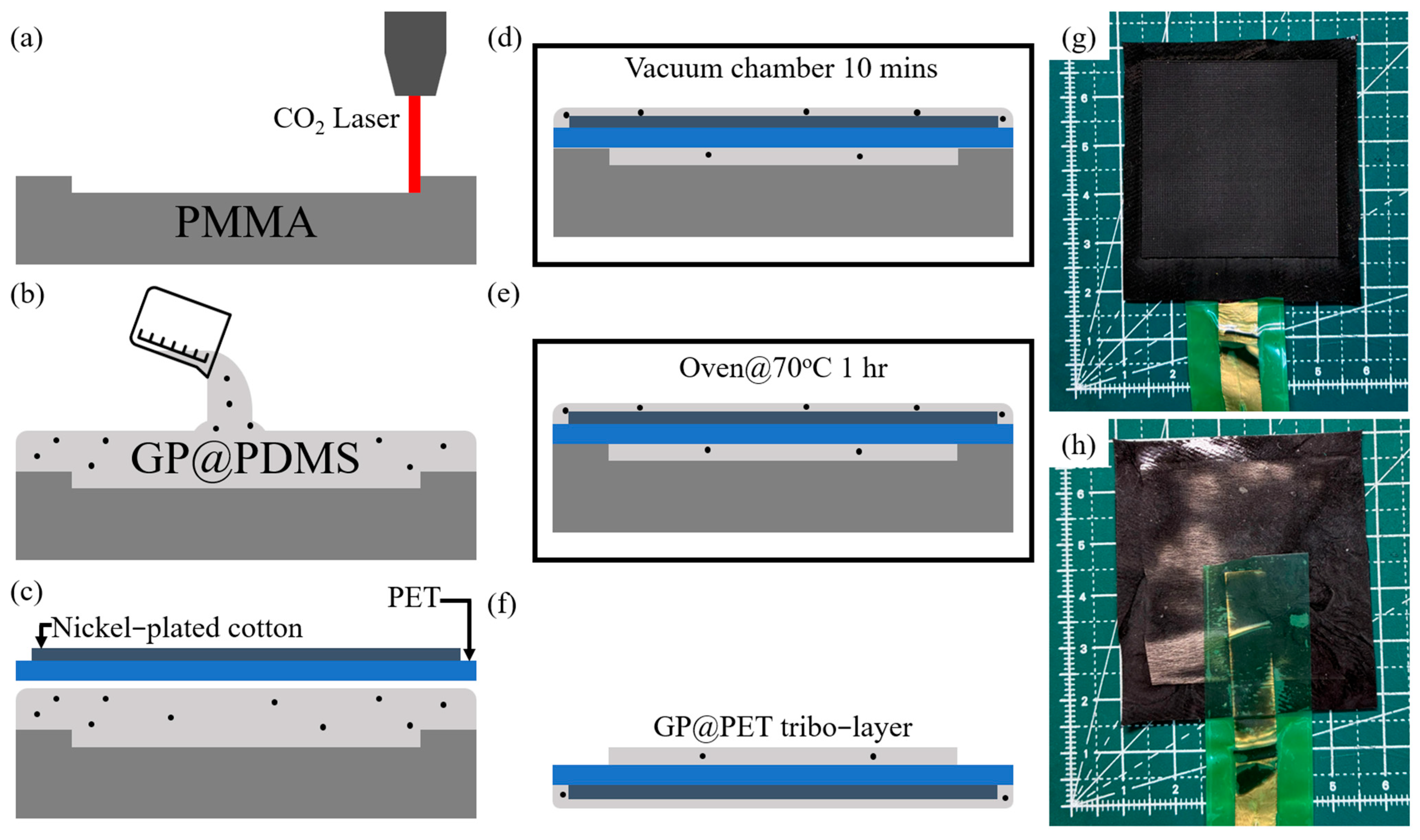
Figure 1. Process flow of GP@PET-TENG fabrication: (a) Use a CO2 laser to cut a 40 × 40 × 1 mm3 groove on an 50 × 50 × 5 mm3 PMMA mold; (b) Pour a mixture of PDMS and 1~5%wt graphite powder into the PMMA mold; (c) Place the PET, pre-attached with nickel-coated fabric, onto the GP@PDMS and allow it to sink into the mixture; (d) Place the sample and mold into a vacuum chamber for 10 min to remove air bubbles; (e) Place the sample and mold into an oven at 70 °C for 1 h to cure; (f) Demold to obtain the GP@PET tribo-layer; Photograph of: (g) the front side and (h) the back side of the fabricated GP@PET tribo-layer.
Sensors 25 06409 g001
Figure 2. Platform used for evaluating the output performance of TENG: (a) Schematic diagram of the setup and (b) corresponding photograph. The platform is driven by a pneumatic cylinder operating at a frequency of about 7 Hz and a force of 50 N. The PDMS tribo-layer of the TENG is fixed on the stationary base, while the aluminum electrode and acrylic plate are mounted on the moving part to form a vertical contact–separation mode TENG with a stroke of 5 mm. The two electrodes are connected to a digital multimeter (DMM6500) to measure the open-circuit voltage and short-circuit current.
Sensors 25 06409 g002
Figure 3. Comparison of output (a) Voc and (b) Isc of PET-TENGs with different graphite doping concentrations, and (c) the output voltage of 3%wt GP@PET-TENG under over 2000 cycles of contact–separation. The Voc values for PET-TENGs with 0% (pure), 1%, 2%, 3%, 4%, and 5% wt graphite doping are 103.3 V, 118.8 V, 157.4 V, 202.1 V, 145.5 V, and 113.0 V, respectively; the corresponding Isc values are 60.7 μA, 71.1 μA, 87.2 μA, 105.1 μA, 83.7 μA, and 64.3 μA. Among them, the 3% wt GP@PET-TENG exhibits the highest output in both Voc and Isc, representing a 1.96-fold and 1.73-fold increase, respectively, compared to the undoped PET-TENG. In (c), the output voltage of the 3% wt GP@PET-TENG remains stable over 2000 cycles of contact–separation, demonstrating its durability under repeated loading.
Sensors 25 06409 g003
Figure 4. (a) Output voltage and current trends of the 3%wt GP@PET-TENG under different external loads. At an external load of 1 MΩ, the 3%wt GP@PET-TENG achieves its maximum output power of 4.15 mW (2.59 W/m2), as calculated using the formula P = I × V; (b) The corresponding output powers under different load resistances are 228.38 nW (142.75 μW/m2) @ 1 kΩ, 769 μW (480.63 mW/m2) @ 10 kΩ, 728.78 μW (455.49 mW/m2) @ 100 kΩ, 4.15 mW (2.59 W/m2) @ 1 MΩ, 3.64 mW (2.28 W/m2) @ 5 MΩ, and 3.66 mW (2.29 W/m2) @ 10 MΩ.
Sensors 25 06409 g004
Figure 5. Performance test of the 3%wt GP@PET-TENG in driving electronic components: (a) The 3%wt GP@PET-TENG successfully charges capacitors of 2.2 μF, 0.47 μF, and 0.33 μF to 1.2 V, 1.1 V, and 1.0 V within 23 s, 5 s, and 1 s, respectively, and discharges them within 18 s, 5 s, and 1 s; (b) Repeated charge–discharge voltage cycles of the 0.47 μF capacitor demonstrate the high repeatability of the 3%wt GP@PET-TENG in charging and discharging capacitors; (c) The 3%wt GP@PET-TENG is capable of simultaneously lighting up 200 LEDs; (d) After charging a 0.47 μF capacitor, the stored energy is used to power an electronic temperature–humidity sensor, demonstrating the potential of the 3%wt GP@PET-TENG to drive small electronic sensing devices.
Sensors 25 06409 g005
Figure 6. A single-electrode mode TENG is formed by combining the 3%wt GP@PET tribo-layer with human skin, and used to capture joint bending motions and convert them into voltage signals. (a) The 3%wt GP@PET tribo-layer is attached to the back of the subject’s third finger joint; (b) when the subject clenched their fist, the skin contacts the tribo-layer and separates upon relaxation, completing a contact-separation cycle; (c) a voltage signal with a peak output of 0.6 V is generated during the motion; (d) the tribo-layer is also attached to the back of the wrist joint; (e) when the wrist bends, contact and subsequent separation occur between the skin and the tribo-layer; (f) this motion similarly generates a voltage output of 0.6 V. These signals can be further utilized for human motion tracking and control applications in the future.
Sensors 25 06409 g006
Disclaimer/Publisher’s Note: The statements, opinions and data contained in all publications are solely those of the individual author(s) and contributor(s) and not of MDPI and/or the editor(s). MDPI and/or the editor(s) disclaim responsibility for any injury to people or property resulting from any ideas, methods, instructions or products referred to in the content.