Article

An Area-Efficient Readout Circuit for a High-SNR Triple-Gain LOFIC CMOS Image Sensor †

1
Research Organization of Science and Engineering, Ritsumeikan University, 1-1-1 Noji-Higashi, Kusatsu 525-8577, Japan
2
Brillnics Japan Inc., Omori Prime Building 7F, 6-21-12 Minami-Oi, Shinagawa-ku, Tokyo 140-0013, Japan
*
Author to whom correspondence should be addressed.
This paper is an extended version of our paper published in 2025 IEEE International Symposium on Circuits and Systems (ISCAS), London, UK, 25–28 May 2025: Ai Otani, Hiroaki Ogawa, Ken Miyauchi, Yuki Morikawa, Hideki Owada, Isao Takayanagi and Shunsuke Okura. “An Area-Efficient Readout Circuit for a High-SNR Triple-Gain LOFIC CMOS Image Sensor”.
Sensors 2025, 25(19), 6093; https://doi.org/10.3390/s25196093
Submission received: 1 August 2025 / Revised: 17 September 2025 / Accepted: 22 September 2025 / Published: 2 October 2025

Abstract

A lateral overflow integration capacitor (LOFIC) CMOS image sensor (CIS) can achieve high-dynamic-range (HDR) imaging by combining a low-conversion-gain (LCG) signal with a high-conversion-gain (HCG) signal. However, the signal-to-noise ratio (SNR) drops at the switching point from HCG signal to LCG signal due to the significant pixel noise in the LCG signal. To address this issue, a triple-gain LOFIC CIS with a middle-conversion-gain (MCG) signal has been introduced. In this work, we propose an area-efficient readout circuit for the triple-gain LOFIC CIS, using amplifier and capacitor sharing techniques to process the HCG, MCG, and LCG signals. A test chip of the proposed readout circuit was fabricated using the 0.18 μ m CMOS process. The area overhead was only 7.6 % , and the SNR drop was improved by 8.05 dB compared to the readout circuit for a dual-gain LOFIC CIS.

1. Introduction

CMOS image sensors (CISs) used in conditions of extreme illumination (e.g., outside) require high-dynamic-range (HDR) imaging technology to avoid underexposure and overexposure of various objects in a scene. Many approaches have been proposed to realize HDR CISs, such as logarithmic compression [1,2], multiple-exposure HDR (MEHDR) [3,4,5,6], dual-conversion-gain (DCG) pixels [7,8,9,10,11,12], and lateral overflow integration capacitor (LOFIC) pixels [7,13,14,15,16,17,18,19,20,21]. LOFIC pixels promise a linear response and reduced motion artifacts. MEHDR images that combine two images taken at different exposure times will cause motion artifacts due to the misalignment of the timings. On the other hand, SEHDR systems, such as LOFIC, combine two images taken at the same exposure time with different gains: low conversion gain (LCG) and high conversion gain (HCG). Thus, SEHDR has an advantage for mitigating motion artifacts [22]. The LOFIC pixel uses an LCG signal to process large maximum signal charges and an HCG signal to reduce dark noise for HDR imaging. However, the LCG pixel reset noise is not canceled due to uncorrelated double sampling, while the HCG pixel reset noise is canceled by correlated double sampling (CDS). Consequently, the signal-to-noise ratio (SNR) drops at the switching point from an HCG to LCG signal. The SNR drop can be mitigated by adding a middle-conversion-gain (MCG) signal, which shifts the switching point of the LCG signal towards a higher signal level. Although several architectures using MCG signals [19,20,21,23] have been proposed, these studies have primarily focused on increasing the dynamic range by enlarging the pixel size or reducing motion artifacts. Additionally, the peripheral circuit area is large because a three-channel readout circuit is required to read the HCG, MCG, and LCG signals [24]. In this work, we propose an area-efficient readout circuit for the triple-gain LOFIC CIS by using amplifier and capacitor sharing techniques based on our previous design for a conventional dual-gain LOFIC CIS [25]. The proposed readout circuit is designed to minimize the SNR drop while maintaining a small pixel area and suppressing motion artifacts. A test chip of the readout circuit was fabricated using a 0.18 μ m CMOS process and was evaluated to estimate the SNR. Our contributions are summarized as follows:
  • To mitigate the SNR drop, we propose the triple-gain LOFIC CIS without enlarging the pixel area or degrading motion artifacts.
  • We propose a readout circuit that is area-efficient for the triple-gain LOFIC CIS.
  • We evaluate a fabricated test chip and estimate the SNR.
Section 2 provides a voltage-level diagram for designing a triple-gain readout circuit for an LOFIC pixel. The proposed readout circuit is described in Section 3, followed by the measurement results of a fabricated test chip shown in Section 4. Section 5 provides a summary of this work.

Updates from the Conference Proceeding

A conference proceeding version of this paper appeared in the 2025 IEEE International Symposium on Circuits and Systems (ISCAS) [26], and this extended version contains the following new content:
  • Pixel- and circuit-gain combination for the MCG signal (Section 2.1, Figure 1).
  • Details of the baseline circuit and comparison with the proposed readout circuit (Section 3.1, Figure 3).
  • Noise analysis of baseline circuit and proposed readout circuit (Figure 4 and Figure 6).
  • A discussion of this study and a comparison with other works (Section 4).

2. Concept-Level Design

This section presents a method to generate the MCG signal, in addition to the conventional HCG and LCG signals, without increasing the pixel area. The MCG signal can be obtained either by combining a high pixel gain with a low circuit gain or a low pixel gain with a high circuit gain. First, the combination for the MCG signal is determined based on the circuit noise performance. Then, a voltage-level diagram is examined for the triple-gain LOFIC CIS using the selected MCG configuration.

2.1. Pixel- and Circuit-Gain Combination for the MCG Signal

In our conventional dual-gain LOFIC CIS [25], the HCG signal is generated by a high pixel gain and a high circuit gain, while the LCG signal is generated by a low pixel gain and a low circuit gain, as shown in Figure 1. The full well capacity (FWC) for HCG signal is 735 e , provided by S m a x / A c i r / A p i x , where S m a x is a maximum output signal of 0.8 V; A c i r and A p i x are circuit gain, including a pixel source-follower (SF) gain of 6.8 × and a pixel conversion gain of 160 μ V / e [16], respectively. The floor noise for HCG signal is 0.96 e rms , provided by N/ A c i r / A p i x , where N is the output floor noise of 1045 μ V rms based on previous work [25]. While the input-referred noise is very small, the FWC is limited. Similarly, the FWC for LCG signal is 130 ke , provided by S m a x / A c i r / A p i x , where S m a x is a maximum output signal of 0.8 V; A c i r and A p i x are circuit gain, including a pixel SF gain of 0.61 × and a pixel conversion gain of 10 μ V / e [16], respectively. The floor noise for LCG signal is 53.3 e rms , provided by N/ A c i r / A p i x , where N is the output floor noise of 326.1 μ V rms based on previous work [25]. While the FWC is very large, the input-referred noise is considerably large. Thus, the signal-to-noise ratio (SNR) at the switching point from the HCG to LCG signal is provided by 735 e / 53.3 e rms = 22.8 dB, where the noise will be visible because the SNR is below 30 dB [27].
To generate the MCG signal, two candidates are considered: (1) high pixel gain combined with low circuit gain; and (2) low pixel gain combined with high circuit gain. This is because the selectable pixel gain is constrained to either high or low in order to maintain a compact pixel area, as in the conventional dual-gain LOFIC pixels [16]. The FWC for MCG (1) signal is 7.0 ke , provided by S m a x / A c i r / A p i x , where S m a x is a maximum output signal of 0.8 V; A c i r and A p i x are circuit gain, including a pixel SF of 0.71 × and a pixel conversion gain of 160 μ V / e [16], respectively. The floor noise for MCG (1) signal is 2.85 e rms , provided by N/ A c i r / A p i x , where N is the output floor noise of 326.1 μ V rms based on previous work [25]. The SNR at the switching point from HCG to MCG (1) is 735 e / 2.85 e rms = 48.2 dB. On the other hand, the SNR at the switching point from MCG (1) to LCG is 7.0 ke / 53.3 e rms = 42.3 dB. Similarly, the input FWC values of MCG (2) are 11.8 ke , provided by S m a x / A c i r / A p i x , where S m a x is a maximum output signal of 0.8 V; A c i r and A p i x are circuit gain, including pixel SF of 6.8 × and a pixel conversion gain of 10 μ V / e [16], respectively. The floor noise for MCG (2) signal is 15.4 e rms , provided by N/ A c i r / A p i x , where N is the output floor noise of 1045 μ V rms based on previous work [25]. The SNR at the switching point from HCG to MCG (2) is 735 e / 15.4 e rms = 33.6 dB. On the other hand, the SNR at the switching point from MCG (2) to LCG is 11.8 ke / 53.3 e rms = 46.9 dB. Based on these rough estimations, MCG (1) is selected because of its larger margin relative to the 30 dB criterion. Additionally, it is noted that photon shot noise dominates at the switching point to the LCG signal.

2.2. Voltage-Level Diagram

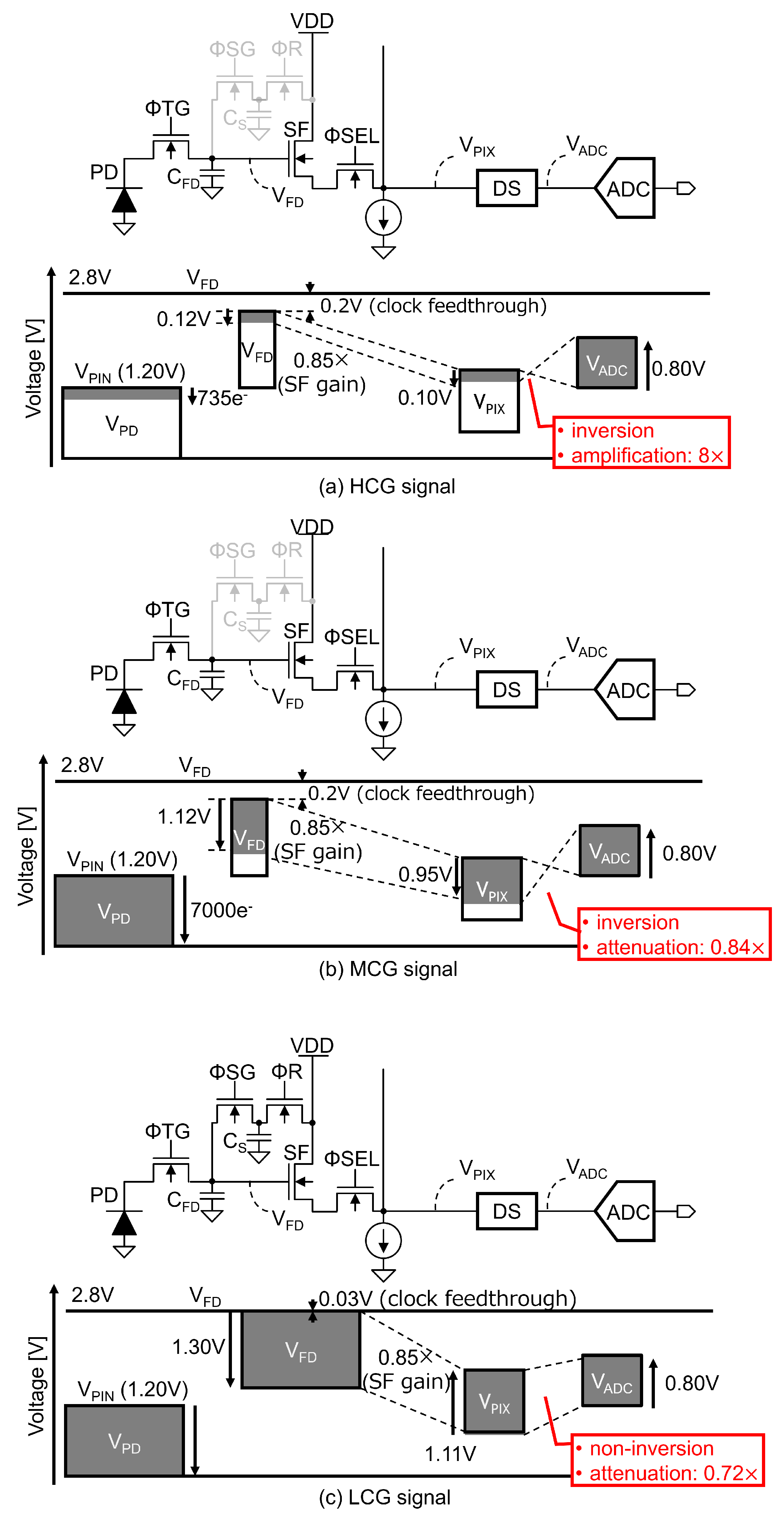
For the triple-gain LOFIC CIS employing the selected MCG configuration, combining the high pixel gain with the low circuit gain, a detailed voltage-level diagram was designed, as shown in Figure 2, including the pinning voltage of the photo-diode (PD) ( V P I N ), the signal voltage swing at the floating diffusion (FD) node ( V F D ) and at the pixel output ( V P I X ), and the input to an ADC ( V A D C ). For the HCG signal shown in Figure 2a, the voltage gain of the double-sampling (DS) circuit is selected as 8 × , such that the input-referred circuit noise can be decreased and a high dynamic range can be achieved. The input window of the DS circuit, which derives from the difference between the reset level and the signal level from the pixel output, is set to 0.10 V for the 0.80 V ADC input window [28], and the signal voltage swing at the FD node is limited to below 0.12 V with a 0.85 × SF gain. For the MCG signal shown in Figure 2b, the PD FWC and C F D are assumed to be 7000 e [16] and 1 fF, respectively, and the maximum signal voltage swing at the FD node is 1.12 V. Even though the clock feed-through on a small C F D can be as large as 0.20 V when the Φ S G is turned off, there is still a sufficient voltage margin to transfer the photo-electrons integrated in the PD to the FD node. The input window of the DS circuit is 0.95 V with an SF, and the voltage gain of the DS circuit is set to 0.84 × for the ADC input window. For the LCG signal shown in Figure 2c, the maximum voltage swing at the FD node is set to 1.30 V in order to read the photo-electrons integrated in the PD, FD, and C S . The input window of the DS circuit is set to 1.11 V with an SF, and the gain of the DS circuit is set to 0.72 × for the ADC input window. The clock feed-through on C F D and C S is as small as 0.03 V when the Φ R is turned off. Hence, the voltage margin required to transfer the photo-electrons integrated in the PD to the FD node remains even for large-FD voltage swings. These level diagrams show that the HCG and MCG signals are inverted, while the LCG signal is not, which enables sharing an ADC for the triple-gain signals.

3. Proposed Readout Circuit for a Triple-Gain LOFIC CIS

As the three-channel readout circuit [24] used to read HCG, MCG, and LCG signals in triple-gain LOFIC CIS leads to an increased chip size, we propose a single-channel readout circuit for the triple-gain LOFIC CIS. First, a baseline circuit is presented, followed by an enhanced design aimed at reducing circuit noise.

3.1. Baseline Readout Circuit

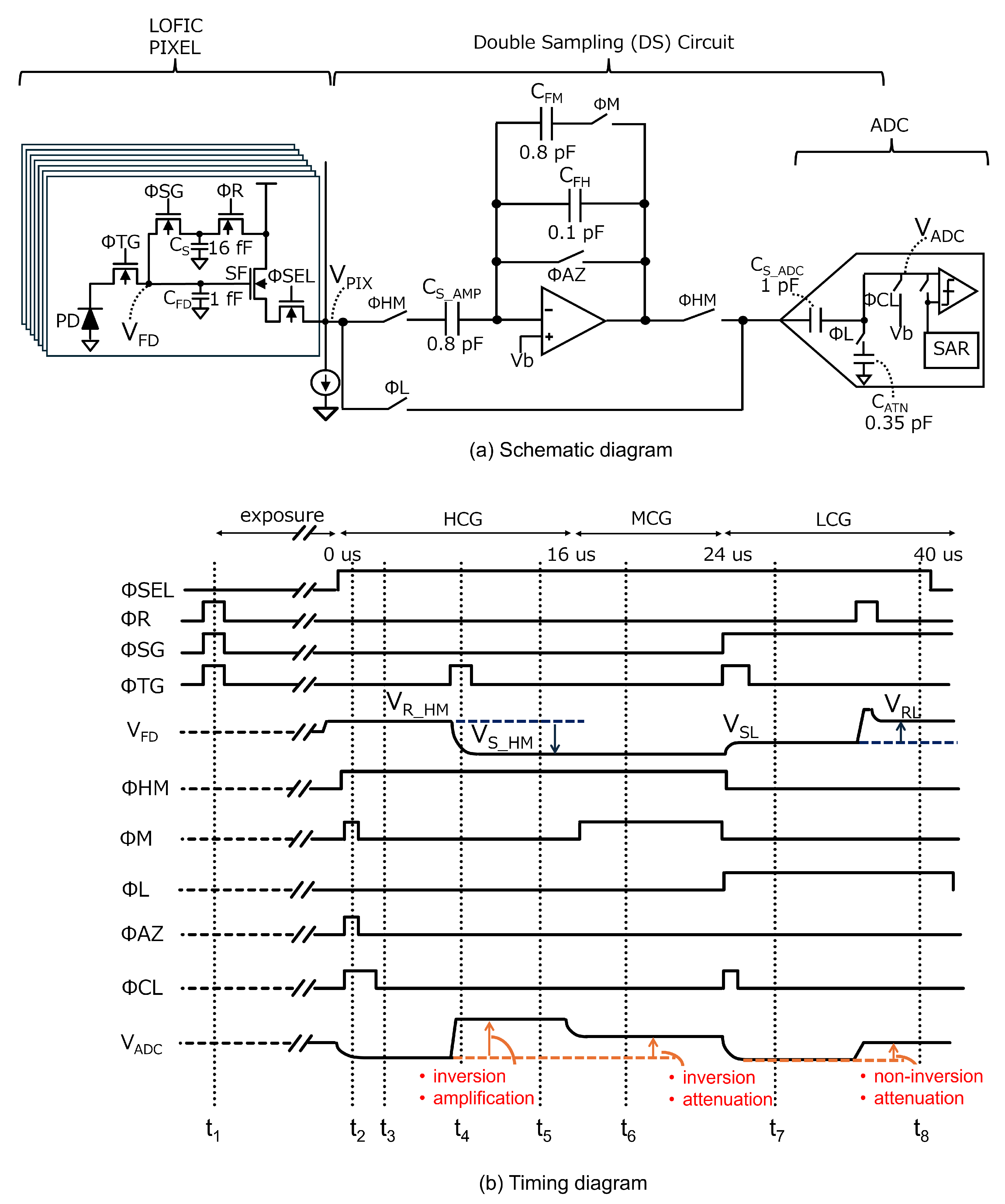
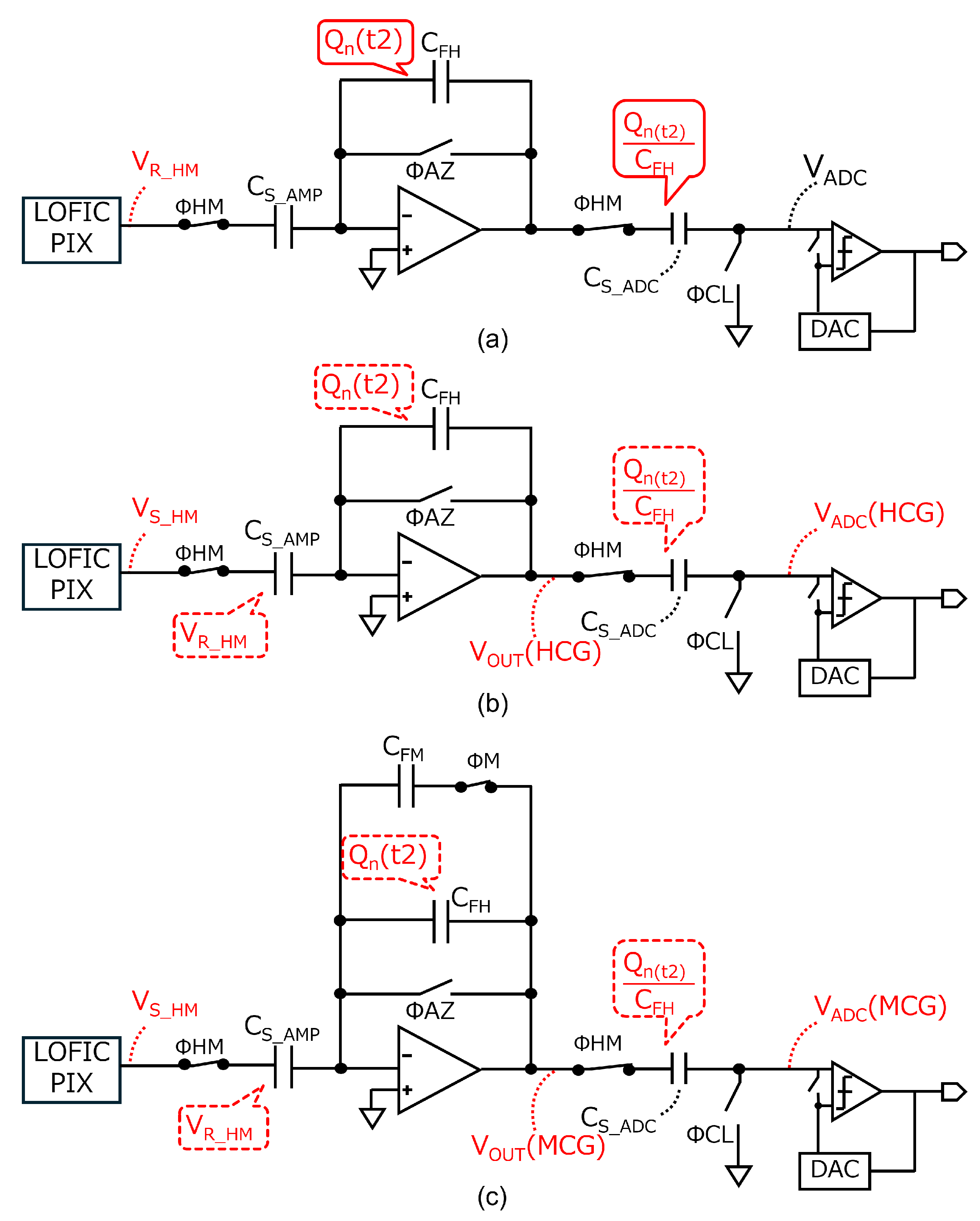
A baseline readout circuit for the triple-gain LOFIC CIS is shown in Figure 3. An amplifier and capacitor are shared for the HCG and MCG signals, and an attenuation capacitor for the LCG signal is shared with a sampling capacitor of an ADC, in which the ADC subsequently processes the HCG, MCG, and LCG signals. This baseline readout circuit is based on our previous design for a conventional dual-gain LOFIC CIS [25], with only one additional feedback capacitor C F M [29,30] introduced to implement the inverted attenuator for the MCG signal. Figure 3b shows a timing diagram of the baseline readout circuit. The total conversion period is 40 μ s and has increased by 8 μ s compared to dual-gain LOFIC CIS [25] but remains less than 1.5 times. First, Φ S G , Φ R , and Φ T G are all toggled to reset the PD, the floating diffusion capacitor C F D , and an overflow photo-electron integration capacitor C S at t 1 prior to starting the exposure. When the exposure is complete, Φ S E L becomes high in a given pixel row, and the pixel reset levels for HCG and MCG ( V R _ H M ) are output from the selected pixel at t 2 . At this time, Φ H M values are high to store A S F · ( V R _ H M V G S _ S F ) in C S _ A M P , where A S F and V G S _ S F are the pixel SF gain and the offset of the pixel SF transistor, respectively. The amplifier reset noise, Q n ( t 2 ) , is generated on the virtual ground node, and Q n ( t 2 ) / C F H is sampled in C S _ A D C after Φ A Z is turned off at t 3 . Figure 4a shows the equivalent circuits at t 3 , where the bias voltage V b and noise other than the amplifier reset noise are considered to be 0 for simplicity.
By toggling Φ T G at t 4 , the pixel signal levels for HCG and MCG ( V S _ H M ), provided by A S F · ( V R _ H M Q S I G / C F D V G S _ S F ) , where Q S I G is the signal charge transferred from the PD, are output from the pixel at t 5 . Figure 4b shows the equivalent circuits at t 5 . At this time, the output signal from the amplifier, V O U T ( H C G ) , is inverted and amplified using C S _ A M P and C F H , as provided by
V O U T ( H C G ) = A S F · C S _ A M P C F H · Q S I G C F D + Q n ( t 2 ) C F H .
The HCG signal input to the ADC, V A D C ( H C G ) , is thus provided by
V A D C ( H C G ) = V O U T ( H C G ) Q n ( t 2 ) C F H
= A S F · C S _ A M P C F H · Q S I G C F D ,
where the amplifier reset noise Q n ( t 2 ) / C F H is removed. Subtracting the pixel reset level from the pixel signal level also cancels the pixel reset noise and the offset of the pixel SF transistor V G S _ S F . After Φ M becomes high, where Figure 4c is the equivalent circuit, the output signal from amplifier, V O U T ( M C G ) , is provided by
V O U T ( M C G ) = A S F · C S _ A M P C F H + C F M · Q S I G C F D + Q n ( t 2 ) C F H + C F M ,
at t 6 . The MCG signal input to the ADC, V A D C ( M C G ) , is inverted and attenuated, as provided by
V A D C ( M C G ) = V O U T ( M C G ) Q n ( t 2 ) C F H
= A S F · C S _ A M P C F H + C F M · Q S I G C F D + Q n ( t 2 ) C F H + C F M Q n ( t 2 ) C F H .
As provided by Equation (6), the amplifier reset noise for the MCG signal is not canceled, which decreases its SNR, resulting in an SNR drop from HCG to MCG. After Φ L and Φ S G become high, the pixel signal level for LCG ( V S L ), provided by A S F · ( V R L Q S I G C F D + C S V G S _ S F ) , is directly stored in C S _ A D C at t 7 . After Φ R is toggled to reset C F D and C S , the pixel reset level for LCG, provided by A S F · ( V R L V G S _ S F ) , is output from the pixel array. The non-inverted and attenuated LCG signal, using C S _ A D C and C A T N , is input to the ADC at t 8 , as provided by
V A D C ( L C G )
= A S F · C S _ A D C C S _ A D C + C A T N · Q S I G C F D + C S + n P I X .
The voltage difference between V R L and V R L results in high pixel reset noise n P I X , provided by 2 k T C F D + C S . The pixel reset noise n PIX is estimated to be 867 μ V rms , assuming C F D = 1.0 fF and C S = 16 fF [16]. LCG pixel reset noise n P I X is not canceled. The SNR of LCG signal is high since LCG has a large signal electron, even if the pixel reset noise n P I X is not canceled. However, the impact of the pixel reset noise n P I X is significant with a small signal electron, leading to the SNR drop. By adding MCG signal, the switching point of the LCG signal shifts towards a higher signal level, resulting in suppression of the SNR drop.

3.2. Proposed Circuit

Although the baseline circuit is area-efficient, it does not cancel the amplifier reset noise for the MCG signal, as provided by Equation (6). This causes an SNR drop from HCG to MCG. To solve this problem, we propose a readout circuit, as shown in Figure 5a, consisting of the same capacitance as the baseline circuit. The changes from the baseline circuit are indicated by red lines. Figure 5b shows a timing diagram of the proposed readout circuit. At t 2 , Φ H and Φ M are high, and A S F · ( V R _ H M V G S _ S F ) is stored in C S H and C S M , respectively. The amplifier reset noise, Q n ( t 2 ) / C F , is sampled in C S _ A D C after Φ A Z is turned off at t 3 . Figure 6a shows the equivalent circuits at t 3 , where V b and noise other than the amplifier reset noise are considered to be 0 for simplicity.
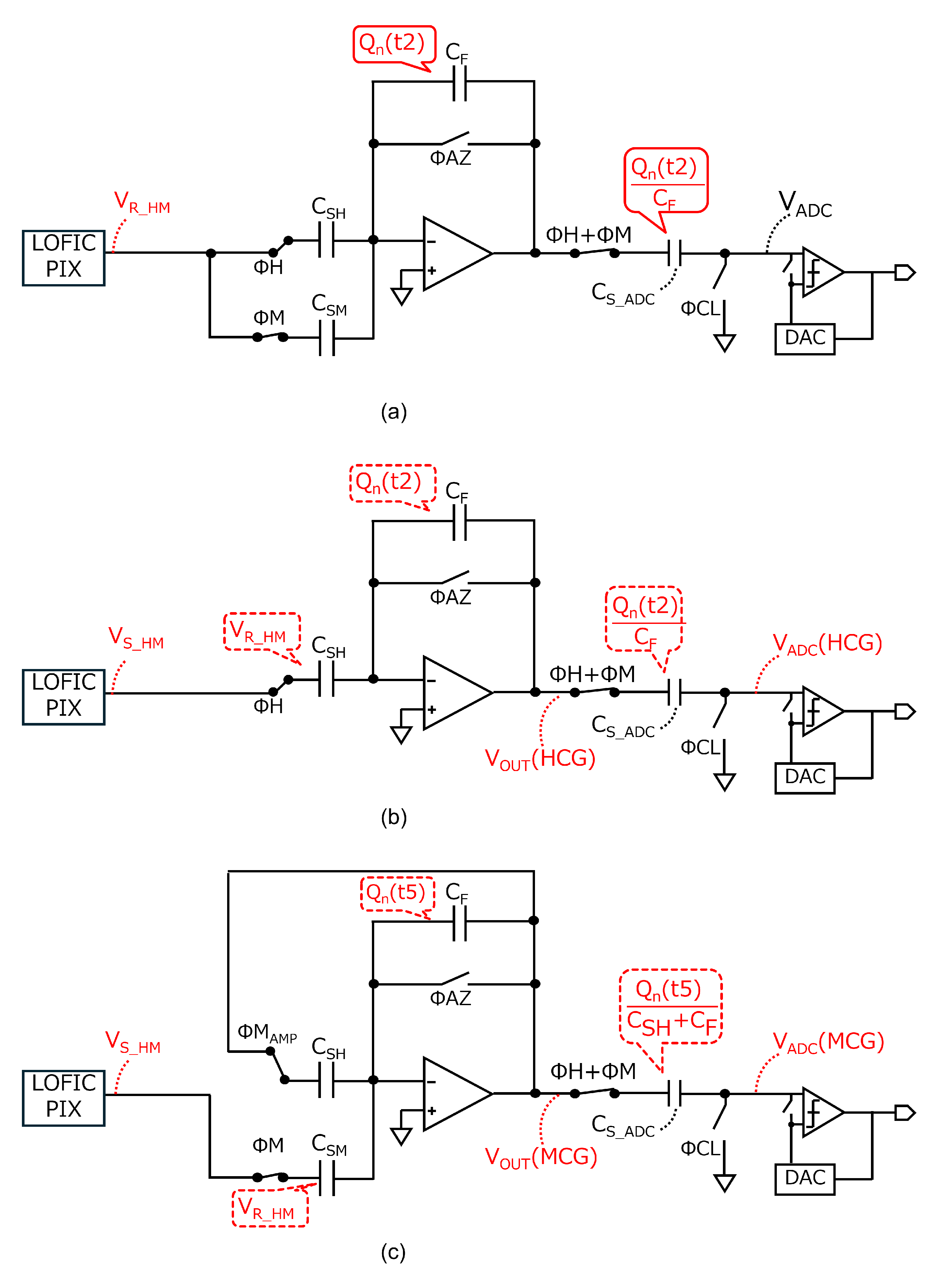
After Φ M becomes low and Q S I G is transferred from the PD at t 4 , the pixel signal levels for HCG and MCG ( V S _ H M ) are output from the pixel at t 5 , as shown in Figure 6b. At this time, the output signal from amplifier, V O U T ( H C G ) , is inverted and amplified using C S H and C F , as provided by
V O U T ( H C G ) = A S F · C S H C F · Q S I G C F D + Q n ( t 2 ) C F .
The HCG signal input to the ADC, V A D C ( H C G ) , is thus provided by
V A D C ( H C G ) = V O U T ( H C G ) Q n ( t 2 ) C F
= A S F · C S H C F · Q S I G C F D .
The amplifier reset noise is canceled for the HCG signal, as in the baseline circuit. Before reading out the MCG signal, Φ M A M P becomes high, and Φ A Z is toggled to reset the charge stored in C S H and C F at t 6 . At this time, the amplifier reset noise Q n ( t 6 ) is generated, and Q n ( t 6 ) / ( C S H + C F ) is sampled in C S _ A D C after Φ A Z is turned off at t 7 . At this time, Φ M is high to set C S M as a sampling capacitor and to reuse C S H as a feedback capacitor, respectively. The equivalent circuit at t 7 is shown in Figure 6c. The output signal from amplifier, V O U T ( M C G ) , is inverted and attenuated using C S M and C S H + C F , as provided by
V O U T ( M C G ) = C S M C S H + C F · A S F · Q S I G C F D + Q n ( t 6 ) C S H + C F .
The MCG signal input to the ADC, V A D C ( M C G ) , is thus provided by
V A D C ( M C G ) = V O U T ( M C G ) Q n ( t 6 ) C S H + C F
= C S M C S H + C F · A S F · Q S I G C F D .
Due to autozeroing before readout of the MCG signal, the amplifier reset noise is also canceled for the MCG signal. The operation from t 8 to t 9 is the same as that described for the baseline circuit from t 7 to t 8 .

4. Fabrication and Evaluation of a Test Chip

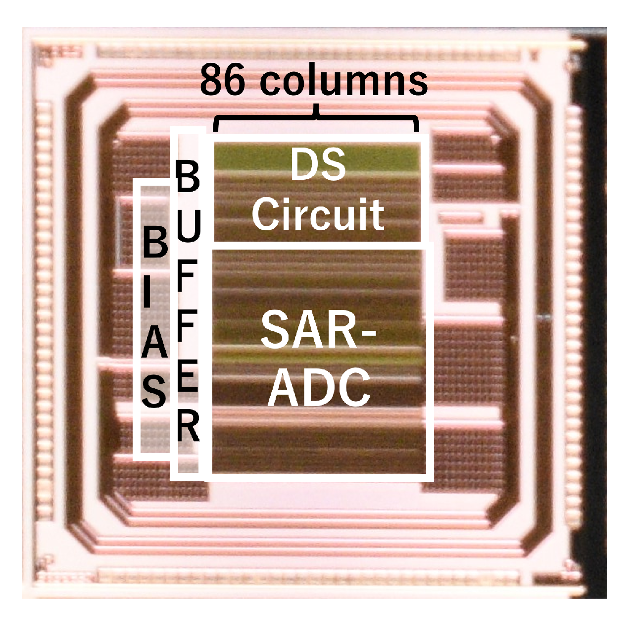
A test chip of the proposed readout circuit for the triple-gain LOFIC CIS was fabricated using a 0.18 μ m 1P5M CMOS process with MIM capacitors. A photo of the fabricated test chip is shown in Figure 7. The test chip contains the DS circuit, 10-bit SAR-ADC, BIAS, and BUFFER. The LOFIC pixel was not implemented in the test chip. There are 86 columns of DS circuits and ADCs with a pitch of 11.22 μ m laid out in parallel. The circuit area for the triple-gain LOFIC CIS increased by only 7.6 % compared to the readout circuit for the dual-gain LOFIC CIS [25].
Figure 8 shows the measured input and output characteristics of the HCG, MCG, and LCG signals when the power supply voltage V D D is set to 2.8 V. The X-axis represents the voltage difference between the pixel reset level and signal level, and the Y-axis represents the output voltage swing referred from the ADC output. The measured circuit gains of the HCG and MCG signals were 5.67 × and 0.76 × , respectively. These values were lower than the target values of 8.0 × and 0.84 × , respectively. The root cause is suspected to be parasitic capacitance. The measured gain of the LCG signal was 0.62 × , which was also lower than the target value of 0.72 × . Table 1 summarizes the measured circuit gain and the estimated total gain. The estimated total gain is provided by A c i r × A p i x × A S F , where A c i r represents the measured circuit gains, such as 5.67 for HCG, 0.76 for MCG, or 0.62 for LCG; A p i x represents the pixel conversion gains of 160 μ V / e for HCG and MCG and 10 μ V / e for LCG [16]; and A S F is the pixel SF gain of 0.85 × , respectively.
The measured input-referred circuit noise is 0.28 mV rms , 1.39 mV rms , and 0.75 mV rms for the HCG, MCG, and LCG signals, respectively, provided by N o u t p u t / A c i r / A S F , where N o u t p u t is the measured output noise from readout circuit, A c i r is the measured circuit gain, and A S F is pixel SF gain, respectively. The estimated input-referred noise is provided by N m / A p i x , where N m is the measured input-referred circuit noise and A p i x is pixel conversion gain [16], respectively. The input-referred circuit noise for the LOFIC pixel is also summarized in Table 2. For HCG, the input-referred circuit noise is minimized thanks to both high circuit gain and high pixel gain. Similarly, the input-referred circuit noise for MCG is lower than that for LCG thanks to its higher pixel gain even though the measured noise for MCG is greater than that for LCG because of the additional inverting attenuator.
Figure 9 shows the SNR, which takes into account the theoretical optical shot noise, the theoretical pixel reset noise, and the measured noise of the proposed readout circuit. It is noted that the 1/f noise generated by the pixel SF transistor is mitigated through double sampling for the HCG, MCG, and LCG signals.
At the switching point from HCG to MCG, the SNR drop is only 0.40 dB, which is very small, because the optical shot noise is dominant. The SNR drop at the switching point from MCG to LCG is 4.02 dB, but this will not be visible because the SNR exceeds 30 dB [27]. As the estimated SNR drop for the dual-gain LOFIC CIS is 12.07 dB, the proposed readout circuit improves the SNR drop by 8.05 dB for the triple-gain LOFIC CIS.

Discussion

In the test chip design, 10-bit ADC was implemented. For HCG signal, the total conversion gain is 0.72 e / LSB , which is based on the following parameters; a pixel conversion gain of 160 μ V / e [16], a circuit gain including a pixel SF gain of 6.8 × , and ADC input window of 0.8 V for 1024 LSB. Therefore, the quantization noise of the readout circuit is less than one electron. Although a 12-bit ADC is preferable, a 10-bit ADC remains acceptable to meet the performance requirements of our target LOFIC CIS.
Also in the test chip design, the conversion period is constrained by the A/D conversion period, which is limited by the maximum clock frequency of the test chip. However, it is estimated that a 2 Mpixel triple-gain LOFIC CIS can achieve a frame rate of approximately 45 fps when used with a high-speed ADC originally designed for a 2 Mpixel 60 fps dual-conversion-gain CMOS image sensor [31].
Although the readout circuit for the LOFIC pixel has rarely been addressed in the published literature, we have provided a specification and performance comparison, as shown in Table 3. The readout circuit for a triple-gain LOFIC CIS reported in [24] employs a three-channel architecture. The single-channel readout circuit used in a global-shutter CMOS image sensor with in-pixel dual storage [32] can be applied to LOFIC CIS. However, since autozeroing of the comparator in the ADC is not feasible for the LCG signal, offset errors may lead to column fixed-pattern noise at the switching point to the LCG signal. The proposed triple-gain readout circuit improves the signal-to-noise ratio (SNR) by 8.05 dB, with no increase in pixel area, a 7.6 % increase in circuit area, and a 25 % reduction in frame rate compared to the case of a dual-gain readout circuit. The triple-gain LOFIC CIS incorporating the proposed readcout circuit will be suitable for cost-sensitive applications such as dashboard cameras and surveillance cameras.

5. Summary

We proposed an area-efficient readout circuit for the triple-gain LOFIC CIS in order to achieve a high SNR. The proposed readout circuit consists of an inverting amplifier, an inverting attenuator, a non-inverting attenuator, and an ADC. By utilizing amplifier and capacitor sharing techniques throughout the readout circuit, the area overhead of the readout circuit for the triple-gain LOFIC CIS is only 7.6 % compared to that of the dual-gain LOFIC CIS. The SNR drops at the switching points from the HCG to MCG signals and from the MCG to LCG signals are 0.40 dB and 4.02 dB, respectively, representing an improvement of up to 8.05 dB. In future work, we will further evaluate the chip, including the LOFIC pixels.

Author Contributions

Conceptualization, S.O.; methodology, A.O. and S.O.; validation, A.O. and H.O. (Hiroaki Ogawa); investigation, Y.M. and H.O. (Hideki Owada); writing—original draft preparation, A.O.; writing—review and editing, K.M. and S.O.; supervision, K.M.; funding acquisition, I.T. All authors have read and agreed to the published version of the manuscript.

Funding

This research received no external funding.

Informed Consent Statement

Not applicable.

Data Availability Statement

The original contributions presented in this study are included in the article. Further inquiries can be directed to the corresponding author.

Acknowledgments

The VLSI chip in this study was fabricated in the chip fabrication program of VDEC, the University of Tokyo, in collaboration with Rohm Corporation and Toppan Printing Corporation.

Conflicts of Interest

Authors Ken Miyauchi, Yuki Morikawa, Hideki Owada and Isao Takayanagi were employed by the Brillnics Japan Inc. All authors declare that the research was conducted in the absence of any commercial or financial relationships that could be construed as a potential conflict of interest.

References

  1. Scheffer, D.; Dierickx, B.; Meynants, G. Random addressable 2048/spl times/2048 active pixel image sensor. IEEE Trans. Electron Devices 1997, 44, 1716–1720. [Google Scholar] [CrossRef]
  2. de Moraes Cruz, C.A.; de Lima Monteiro, D.W.; Souza, A.K.P.; da Silva, L.L.F.; de Sousa, D.R.; de Oliveira, E.G. Voltage Mode FPN Calibration in the Logarithmic CMOS Imager. IEEE Trans. Electron Devices 2015, 62, 2528–2534. [Google Scholar] [CrossRef]
  3. Komobuchi, H. 1/4 inch NTSC Format Hyper-D Range IL-CCD. In Proceedings of the 1995 IEEE Workshop on CCDs and AISs. SS-1, Dana Point, CA, USA, 20 April 1995. [Google Scholar]
  4. Yadid-Pecht, O.; Fossum, E. Wide intrascene dynamic range CMOS APS using dual sampling. IEEE Trans. Electron Devices 1997, 44, 1721–1723. [Google Scholar] [CrossRef]
  5. Takayanagi, I.; Fukunaga, Y.; Yoshida, T.; Nakamura, J. A four-transistor capacitive feedback reset active pixel and its reset noise reduction capability. In Proceedings of the IEEE Workshop on CCD and AIS, Lake Tahoe, NA, USA, 7–9 June 2001; pp. 118–121. [Google Scholar]
  6. Mase, M.; Kawahito, S.; Sasaki, M.; Wakamori, Y.; Furuta, M. A wide dynamic range CMOS image sensor with multiple exposure-time signal outputs and 12-bit column-parallel cyclic A/D converters. IEEE J. Solid-State Circuits 2005, 40, 2787–2795. [Google Scholar] [CrossRef]
  7. Fowler, B.; Liu, C.; Mims, S.; Balicki, J.; Li, W.; Do, H.; Vu, P. Wide dynamic range low light level CMOS image sensor. In Proceedings of the International Image Sensor Workshop, Bergen, Norway, 26–28 June 2009; pp. 1–4. [Google Scholar]
  8. Huggett, A.; Silsby, C.; Cami, S.; Beck, J. A dual-conversion-gain video sensor with dewarping and overlay on a single chip. In Proceedings of the 2009 IEEE International Solid-State Circuits Conference-Digest of Technical Papers, San Francisco, CA, USA, 8–12 February 2009; pp. 52–53. [Google Scholar]
  9. Meynants, G.; Beeckman, G.; Van Wichelen, K.; De Ridder, T.; Koch, M.; Schippers, G.; Bonnifait, M.; Diels, W.; Bogaerts, J. Backside illuminated 84 dB global shutter image sensor. In Proceedings of the International Image Sensor Workshop (IISS), Vaals, The Netherlands, 8–11 June 2015; pp. 220–224. [Google Scholar]
  10. Miyauchi, K.; Mori, K.; Isozaki, T.; Sawai, Y.; Yasuda, N.; Chien, H.C.; Fu, K.W.C.; Takayanagi, I.; Nakamura, J. 4.0 μm Stacked Voltage Mode Global Shutter Pixels with Single Exposure High Dynamic Range and Phase Detection Auto Focus Capability. ITE Trans. Media Technol. Appl. 2022, 10, 234–242. [Google Scholar] [CrossRef]
  11. Cremers, B.; Freson, T.; Esquenet, C.; Vroom, W.; Prathipati, A.K.; Okcan, B.; Luypaert, C.; Jiang, H.; Witters, H.; Compiet, J.; et al. A 5MPixel Image Sensor with a 3.45 μm Dual Storage Global Shutter Back-Side Illuminated Pixel with 90 dB DR . In Proceedings of the 2023 International Image Sensors Workshop, Crieff, UK, 21–25 May 2023; pp. 21–25. [Google Scholar]
  12. Gao, Z.; Park, G.; Fu, L.; Chapinal, G.; Yang, J.; Freson, T.; Qin, Q.; Guo, J.; Zhu, F.; Ding, S.; et al. A 2.2 μm 2-Layer Stacked HDR Voltage Domain Global Shutter CMOS Image Sensor with Dual Conversion Gain and 1.2 e-FPN. In Proceedings of the 2023 International Electron Devices Meeting (IEDM), San Francisco, CA, USA, 9–13 December 2023; pp. 1–4. [Google Scholar]
  13. Chamberlain, S.; Lee, J. A novel wide dynamic range silicon photodetector and linear imaging array. IEEE Trans. Electron Devices 1984, 31, 175–182. [Google Scholar] [CrossRef]
  14. Sakai, S.; Tashiro, Y.; Kawada, S.; Kuroda, R.; Akahane, N.; Mizobuchi, K.; Sugawa, S. Pixel Scaling in Complementary Metal Oxide Silicon Image Sensor with Lateral Overflow Integration Capacitor. Jpn. J. Appl. Phys. 2010, 49, 04DE03. [Google Scholar] [CrossRef]
  15. Sakano, Y.; Sakai, S.; Tashiro, Y.; Kato, Y.; Akiyama, K.; Honda, K.; Sato, M.; Sakakibara, M.; Taura, T.; Azami, K.; et al. 224-ke saturation signal global shutter CMOS image sensor with in-pixel pinned storage and lateral overflow integration capacitor. In Proceedings of the 2017 Symposium on VLSI Circuits, Kyoto, Japan, 5–9 June 2017; pp. C250–C251. [Google Scholar]
  16. Takayanagi, I.; Miyauchi, K.; Okura, S.; Mori, K.; Nakamura, J.; Sugawa, S. A 120-ke Full-Well Capacity 160 μV/e Conversion Gain 2.8-μm Backside-Illuminated Pixel with a Lateral Overflow Integration Capacitor. Sensors 2019, 19, 5572. [Google Scholar] [CrossRef] [PubMed]
  17. Shike, H.; Kuroda, R.; Kobayashi, R.; Murata, M.; Fujihara, Y.; Suzuki, M.; Harada, S.; Shibaguchi, T.; Kuriyama, N.; Hatsui, T.; et al. A Global Shutter Wide Dynamic Range Soft X-Ray CMOS Image Sensor with Backside- Illuminated Pinned Photodiode, Two-Stage Lateral Overflow Integration Capacitor, and Voltage Domain Memory Bank. IEEE Trans. Electron Devices 2021, 68, 2056–2063. [Google Scholar] [CrossRef]
  18. Oikawa, T.; Kuroda, R.; Takahashi, K.; Shiba, Y.; Fujihara, Y.; Shike, H.; Murata, M.; Kuo, C.C.; da Silva, Y.R.S.C.; Goto, T.; et al. A 1000 fps high SNR voltage-domain global shutter CMOS image sensor with two-stage LOFIC for in-situ fluid concentration distribution measurements. In Proceedings of the Proceedings IISW, Virtual, 20–23 September 2021; pp. 258–261. [Google Scholar]
  19. Oh, M.; Velichko, S.; Johnson, S.; Guidash, M.; Chang, H.C.; Tekleab, D.; Gravelle, B.; Nicholes, S.; Suryadevara, M.; Collins, D.; et al. Automotive 3.0 μm Pixel High Dynamic Range Sensor with LED Flicker Mitigation. Sensors 2020, 20, 1390. [Google Scholar] [CrossRef] [PubMed]
  20. Fujihara, Y.; Murata, M.; Nakayama, S.; Kuroda, R.; Sugawa, S. An Over 120 dB Single Exposure Wide Dynamic Range CMOS Image Sensor with Two-Stage Lateral Overflow Integration Capacitor. IEEE Trans. Electron Devices 2021, 68, 152–157. [Google Scholar] [CrossRef]
  21. Velichko, S.; Jasinski, D.; Guidash, M.; Tekleab, D.; Innocent, M.; Perkins, A.; Amanullah, S.; Suryadevara, M.; Silsby, C.; Beck, J. Automotive 3 μm HDR Image Sensor with LFM and Distance Functionality. IEEE Trans. Electron Devices 2022, 69, 2951–2956. [Google Scholar] [CrossRef]
  22. Takayanagi, I.; Kuroda, R. HDR CMOS Image Sensors for Automotive Applications. IEEE Trans. Electron Devices 2022, 69, 2815–2823. [Google Scholar] [CrossRef]
  23. Asatsuma, T.; Sakano, Y.; Iida, S.; Takami, M.; Yoshiba, I.; Ohba, N.; Mizuno, H.; Oka, T.; Yamaguchi, K.; Suzuki, A.; et al. Sub-pixel architecture of cmos image sensor achieving over 120 db dynamic range with less motion artifact characteristics. In Proceedings of the 2019 International Image Sensor Workshop, Snowbird, UT, USA, 23–27 June 2019; Volume 1. [Google Scholar]
  24. Wakashima, S.; Kusuhara, F.; Kuroda, R.; Sugawa, S. A linear response single exposure CMOS image sensor with 0.5e- readout noise and 76ke- full well capacity. In Proceedings of the 2015 Symposium on VLSI Circuits (VLSI Circuits), Kyoto, Japan, 16–19 June 2015; pp. C88–C89. [Google Scholar] [CrossRef]
  25. Otani, A.; Ogawa, H.; Miyauchi, K.; Han, S.; Owada, H.; Takayanagi, I.; Okura, S. An Area-Efficient up/down Double-Sampling Circuit for a LOFIC CMOS Image Sensor. Sensors 2023, 23, 4478. [Google Scholar] [CrossRef] [PubMed]
  26. Otani, A.; Ogawa, H.; Miyauchi, K.; Morikawa, Y.; Owada, H.; Takayanagi, I.; Okura, S. An Area-Efficient Readout Circuit for a High-SNR Triple-Gain LOFIC CMOS Image Sensor. In Proceedings of the 2025 IEEE International Symposium on Circuits and Systems (ISCAS), London, UK, 25–28 May 2025; pp. 1–5. [Google Scholar] [CrossRef]
  27. Akahane, N.; Adachi, S.; Mizobuchi, K.; Sugawa, S. Optimum Design of Conversion Gain and Full Well Capacity in CMOS Image Sensor with Lateral Overflow Integration Capacitor. IEEE Trans. Electron Devices 2009, 56, 2429–2435. [Google Scholar] [CrossRef]
  28. Takayanagi, I. A Study on Intra-Scene Single-Exposure High-Dynamic Range CMOS Image Sensor Technologies. Ph.D Thesis, Tohoku University, Sendai, Japan, 2020. [Google Scholar] [CrossRef]
  29. Fujimoto, Y.; Akada, H.; Ogawa, H.; Iizuka, K.; Miyamoto, M. A switched-capacitor variable gain amplifier for CCD image sensor interface system. In Proceedings of the 28th European Solid-State Circuits Conference, Florence, Italy, 24–26 September 2002; pp. 363–366. [Google Scholar]
  30. Takahashi, H.; Noda, T.; Matsuda, T.; Watanabe, T.; Shinohara, M.; Endo, T.; Takimoto, S.; Mishima, R.; Nishimura, S.; Sakurai, K.; et al. A 1/2.7-in 2.96 MPixel CMOS Image Sensor with Double CDS Architecture for Full High-Definition Camcorders. IEEE J. Solid-State Circuits 2007, 42, 2960–2967. [Google Scholar] [CrossRef]
  31. Takayanagi, I.; Yoshimura, N.; Mori, K.; Matsuo, S.; Tanaka, S.; Abe, H.; Yasuda, N.; Ishikawa, K.; Okura, S.; Ohsawa, S.; et al. An Over 90 dB Intra-Scene Single-Exposure Dynamic Range CMOS Image Sensor Using a 3.0 μm Triple-Gain Pixel Fabricated in a Standard BSI Process. Sensors 2018, 18, 203. [Google Scholar] [CrossRef] [PubMed]
  32. Sakakibara, M.; Oike, Y.; Takatsuka, T.; Kato, A.; Honda, K.; Taura, T.; Machida, T.; Okuno, J.; Ando, A.; Fukuro, T.; et al. An 83dB-dynamic-range single-exposure global-shutter CMOS image sensor with in-pixel dual storage. In Proceedings of the 2012 IEEE International Solid-State Circuits Conference, San Francisco, CA, USA, 19–23 February 2012; pp. 380–382. [Google Scholar] [CrossRef]
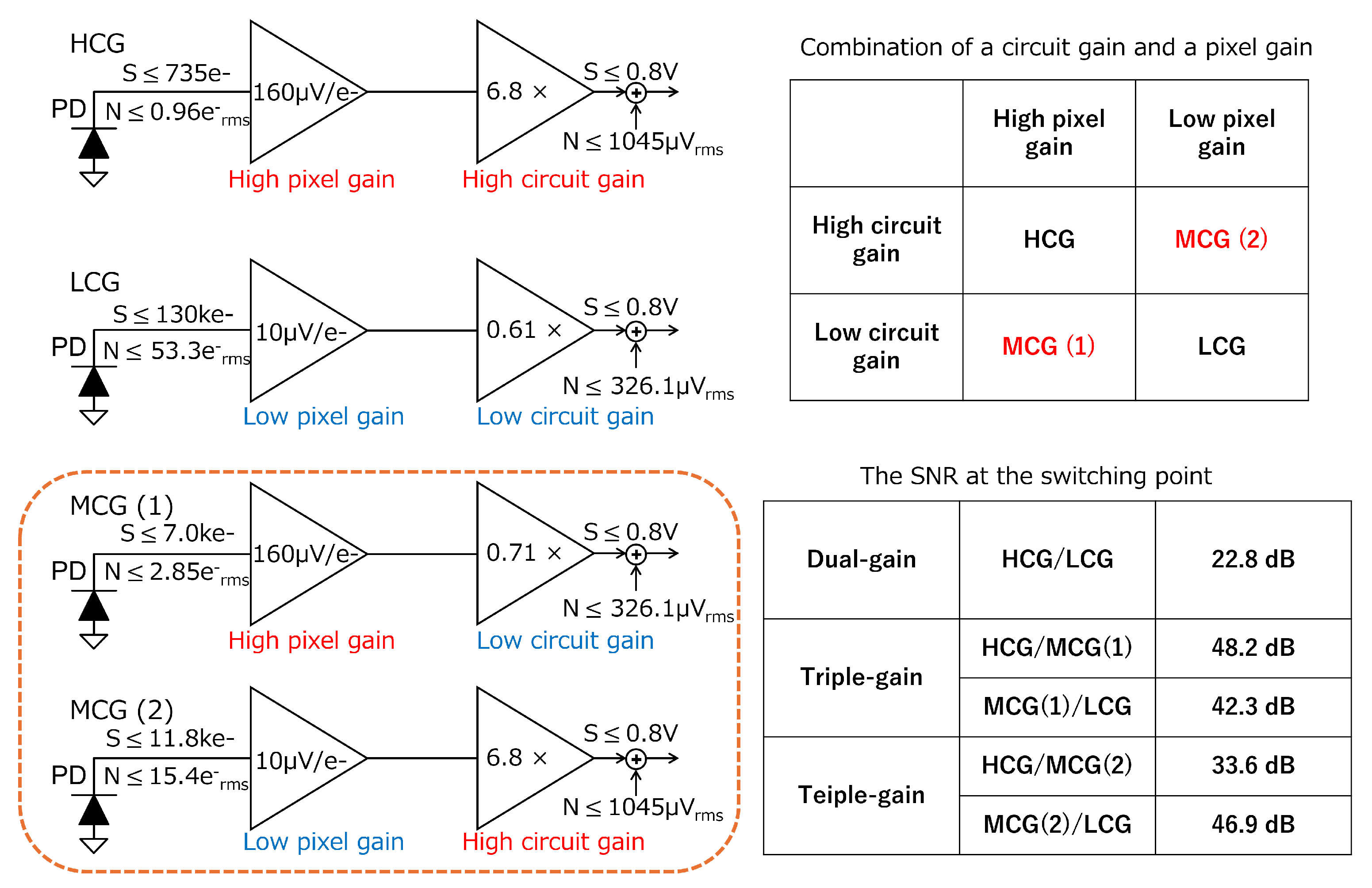
Figure 1. Concept of processing HCG, LCG, and MCG signals.
Sensors 25 06093 g001
Figure 2. The level diagram of LOFIC CIS: (a) HCG signal; (b) MCG signal; (c) LCG signal.
Sensors 25 06093 g002
Figure 3. (a) Schematic diagram and (b) timing diagram of the baseline readout circuit.
Sensors 25 06093 g003
Figure 4. Equivalent circuits of the baseline circuit (a) at t 3 , (b) at t 5 , and (c) at t 6 to analyze the HCG and MCG outputs.
Sensors 25 06093 g004
Figure 5. (a) Schematic diagram and (b) timing diagram of the proposed readout circuit.
Sensors 25 06093 g005
Figure 6. Equivalent circuits of the proposed readout circuit (a) at t 3 , (b) at t 5 , and (c) at t 7 to analyze the HCG and MCG outputs.
Sensors 25 06093 g006
Figure 7. A photo of the fabricated test chip.
Sensors 25 06093 g007
Figure 8. Measured input and output characteristics.
Sensors 25 06093 g008
Figure 9. The SNR taking into account the optical shot noise, the pixel reset noise, and the measured noise of the proposed readout circuit.
Sensors 25 06093 g009
Table 1. Measured circuit gain and estimated total gain.
HCGMCGLCG
Measured circuit gain [V/V] 5.67 0.76 0.62
Estimated total gain [ μ V / e ]771103 5.27
Table 2. Measured and estimated input-referred noise of the proposed readout circuit.
HCGMCGLCG
Measurement [ mV rms ] 0.28 1.39 0.75
Estimation [ e rms ] 1.75 8.69 75.5
Table 3. Performance comparison.
[24][32]This Work
Process180 nm 1P5M90 nm 1P4M180 nm 1P5M
Gaintripledualdualtriple
#Readout circuit311
ADC resolution [bit]N/A1210
LCG autozeroingN/ANoPossible
Readout period [ μ s ]N/AN/A3240
Circuit area [ μ m 2 ]N/AN/A16,21017,438
SNR drop [dB]N/AN/A12.074.02
Disclaimer/Publisher’s Note: The statements, opinions and data contained in all publications are solely those of the individual author(s) and contributor(s) and not of MDPI and/or the editor(s). MDPI and/or the editor(s) disclaim responsibility for any injury to people or property resulting from any ideas, methods, instructions or products referred to in the content.