Abstract
This paper discusses the design, manufacturing, and experimental characterization of a Ka-band fully dielectric reflectarray realized using Zetamix 7.5 ceramic material and additive manufacturing. Properly tuning the infill during the manufacturing process, it is possible to control the permittivity of the material, which can therefore be considered, to all intents and purposes, an additional degree of freedom for optimizing the unit cell and consequently the reflectarray performance. The optimal values of are determined through numerical analysis of the unit cell and experimental characterization of bricks manufactured with different printing parameters. Then, the unit cell is used to design a medium-sized reflectarray with an aperture of 207.4 and a thickness of 0.44, at the design frequency GHz. The full-wave simulations of the designed RA and experimental measurements of a prototype confirm the excellent performance of the antenna, which exhibits a broadband flat response from 28 to 31 GHz and an aperture efficiency exceeding 50%.
1. Introduction
High-gain antennas are essential for modern microwave and millimeter-wave communication systems, including applications such as radar, satellite communications, remote sensing, point-to-point terrestrial links, and deep-space missions. Among others, Reflectarrays (RAs) [1,2] represent a well-assessed solution for realizing such antennas, possessing over other alternatives the advantages of being non-bulky, easy to manufacture, and low-cost.
Although the first RAs were designed assuming their realization with microstrip technology [3,4], alternative fabrication methods have been explored more recently [5,6,7,8,9,10,11,12,13,14,15,16]. A particularly effective solution consists of using dielectric resonator antennas (DRAs) as RA elements. DRAs [17,18,19,20] offer several advantages compared to printed elements, including wider bandwidths, higher radiation efficiency, and lower mutual coupling between elements. Their compatibility with Additive Manufacturing (AM) technologies, also known as 3D printing, provides greater design flexibility and cost-efficiency, enabling rapid prototyping and customized geometries.
The choice of technique adopted for antenna manufacturing has several effects on its features, mainly related to two different aspects. The first one is process accuracy, which is higher for Polymer Jetting (PJ) printers, allowing for the manufacturing of objects with many details, such as RAs working in the Ka band. In contrast, the materials that could be used with these printers are generally characterized by a low relative dielectric constant and high losses. In contrast, printers based on the Fused Deposition Method (FDM) offer lower accuracy, but can work with a broader variety of dielectric materials with different properties. Recently, filaments with high relative permittivities have been introduced. These filaments are particularly suitable for the manufacturing of RF circuits and antennas, as they help to reduce their size [21,22,23,24,25,26,27,28]. Among them, there is Zetamix [29], a ceramic filament developed by Nanoe and available on the market in four different varieties, each characterized by a different value of relative permittivity varying between 2.2 and 10.
This work presents the design, fabrication, and experimental validation of a Ka-band dielectric RA, based on fully dielectric cylindrical Unit Cells (UCs) manufactured using Zetamix with . The novelty of this work lies not only in the design and experimental validation of the RA, but also in the rigorous characterization of the dielectric properties of Zetamix 7.5, which is fundamental when the porosity of the fused material compromises the high permittivity. The advantage of using a material with such a higher value for is that, through the variation of the infill during the manufacturing process, it is possible to tune the final permittivity, adapting it to the application or changing it from one zone to another of the structure under construction [30]. Here, this nice feature has been exploited to optimize the UC and its performance by actually introducing a further degree of freedom in the unit cell design. According to the authors’ knowledge, this is the first time that the permittivity of the dielectric material has been used to optimize the performance of an RA unit cell, in addition to its geometrical parameters. The optimization process was carried out in two steps. First, the numerical analysis of the unit cell was performed for different values of the selected geometrical parameters and . Then, different bricks of the same material, obtained with different printing parameters and, in particular, different infills, were manufactured and experimentally characterized. Through this process, a permittivity close to the value determined through the numerical analysis was obtained and then used to design the reflectarray. Both its full-wave analysis and the experimental characterization of a medium-sized prototype show the good performance of the antenna and confirm the effectiveness of the proposed approach.
2. Unit Cell Characterization
To design a high-performance reflectarray, the unit cell must satisfy several properties, such as the ability to provide a reflection coefficient with magnitude as close to 0 dB as possible and phase that varies smoothly and possibly linearly over a range close to 360 degrees, a low dependence on the incident field’s angle of arrival and frequency. When, as in the present case, a dielectric cell is designed, its performance strongly depends on the material and the manufacturing techniques. The advantage of using a material with a high permittivity is that the optimal values for relative permittivity can be obtained by appropriately controlling the infill [30]. For this reason, Zetamix 7.5 has been selected to enable the dielectric permittivity of the final structure to be tuned, keeping its value sufficiently high to reduce the UC dimensions as much as possible while maintaining the desired electromagnetic performance, contributing to the overall miniaturization and efficiency of the RA.
The geometry considered here for the UC is sketched in Figure 1. A square, uniform layer of dielectric material is deposited with thickness mm above a metallic ground plane. On top of the uniform layer, a cylindrical pillar with diameter d and height is printed in the center of the cell. For the electromagnetic characterization of the UC, this is considered embedded in a periodic lattice with periodicity equal to its dimension mm. Note that the periodicity is slightly less than at the upper end of the considered frequency band, which ranges from 28 GHz to 31 GHz. A full-wave periodic analysis was performed in the frequency domain by using CST Microwave Studio™ (CST 2024). Orthogonal and skew plane wave incidences were considered.

Figure 1.
Geometry of the unit cell: (a) side view; (b) top view.
The diameter d of the pillar is varied to control the phase of the reflection coefficient , while its height and the relative permittivity are used to optimize the UC performance and reduce its size. Three different analyses were performed: first, the height of the pillar was kept fixed and the variation of the magnitude and phase of the reflection coefficient versus the diameter d was obtained for several values of . Then, the effects on the UC performance of the pillar height and the direction of arrival of the incident field were considered.
Figure 2 plots the variation of the magnitude () and phase () of the reflection coefficient for different values of relative permittivity. Examining the curves associated with show that different values of affect both the range of variation and frequency dispersion. In particular, increasing the value of enlarges the phase range, whose minimum occurs for at 28 GHz, and also helps to keep its frequency dependence lower. This behavior seems to favor higher values of permittivity. However, examining the curves related to the magnitude (red curves), it becomes apparent that a second resonance, accompanied by a strong attenuation, appears for at 31 GHz, and therefore, it is advisable to discard that value for .
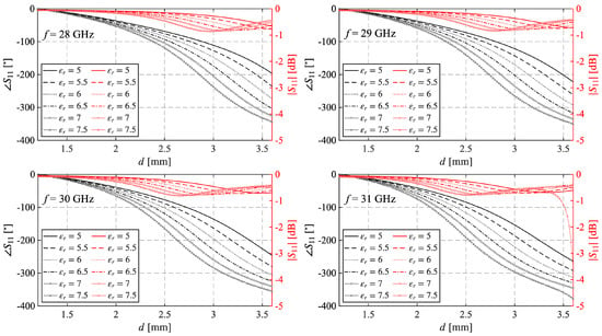
Figure 2.
Variation of and for different values of evaluated in correspondence of 4 frequencies, and inside the considered band mm.
The second analysis is focused on the evaluation of the effect of pillar height on UC performance. Figure 3 shows the variation of and versus d, evaluated at 31 GHz, to check if other resonances occur. Each plot shows results for a different value of , while the curves refer to different values of . As expected, increasing the height of the pillar increases the phase delay dynamics provided by the unit cell. When mm, the phase range varies from approximately for to a range greater than for . However, since the unit cell usually does not cover the full range, and a reasonable value to ensure an acceptable phase error on the RA surface is approximately , the plots in Figure 3 show that this range is never reached with the considered set of values when . Conversely, this range is provided by a pillar with mm and or mm and . Concerning , it never drops below −2 dB in any of the considered cases, even when the relative permittivity is and a second resonance appears at the highest values.
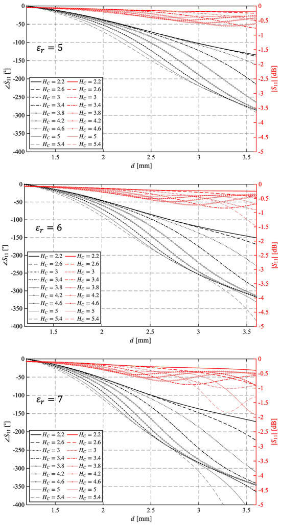
Figure 3.
Variation of and for different values of evaluated for at 31 GHz.
Finally, the curves in the three plots of Figure 4 show the effect of the angle of incidence of the incoming field on the behavior of the unit cell made of a dielectric material with relative permittivity equal to 5, 6, or 7. The results have been obtained at 31 GHz, with mm. In contrast to the previous results, the optimal value for in this case is 5, since the dependence on the direction of arrival of the incident field is minimal.
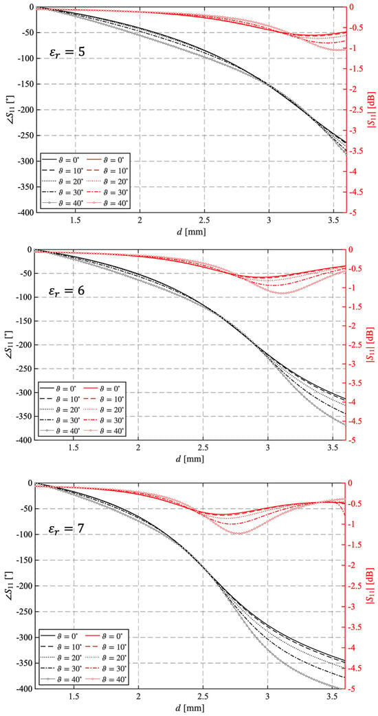
Figure 4.
Variation of and for different values of the angle of incidence evaluated for mm and = 5, 6, 7 at 31 GHz.
Based on these results, it was decided to select a relative permittivity of 6 and mm, as they appear to represent the best compromise between the unit cell’s performance and its size.
3D Printing Parameters Assessment and Material Experimental Characterization
Having fixed the optimal value for , it was necessary to assess the printer parameters to obtain it. To achieve this aim, various brick samples, with nominal dimensions 8.64 mm × 4.32 mm × 3.5 mm, have been manufactured using different configurations of the printing parameters as explained later. The fabrication of the bricks was performed using a Raise3D Pro3 printer [31], the same adopted for the manufacturing of the reflectarray. The nominal dimensions of the bricks match exactly the internal dimensions of the WR34 waveguide used for the permittivity evaluation.
Initially, standard printing parameters within the range provided by Nanoe for Zetamix were used. They are summarized in column 2 of Table 1. A first set of three bricks was manufactured using these parameters and experimentally characterized. A CNC optical measuring system has been employed to investigate their mechanical structure and determine their dimensions. Figure 5a shows a detailed view of a brick sample along the building direction, confirming that the brick exhibits a relatively uniform material distribution due to the 100% infill. However, there are slight variations in size among the bricks, as indicated by the values in Table 2. It is important to note that the samples do not completely fill the WR34 waveguide. Therefore, to eliminate any uncertainties regarding their position, the samples were consistently placed at one corner of the waveguide.

Table 1.
Comparison between recommended and adopted printing parameters for Zetamix 7.5.

Figure 5.
Detailed view of the WR34 samples along the building direction. (a) Sample 1 of the first set, manufactured using a typical printer setup. (b) Sample 1 of the second set, manufactured with values of the printer parameters adjusted for the specific case.

Table 2.
Dimensions of the samples manufactured with the standard printer setup.
The electromagnetic characterization of the samples was carried out by filling the sample into a WR34 waveguide, which was connected to the Vector Network Analyzer (VNA) through a pair of coaxial waveguide launchers. A classical through-reflection-line (TRL) technique has been exploited for accurate calibration. Figure 6 shows the measurement setup and the calibration planes. The material’s characterization in terms of complex dielectric constant is derived by best fitting between the simulated and measured reflection and transmission coefficients.
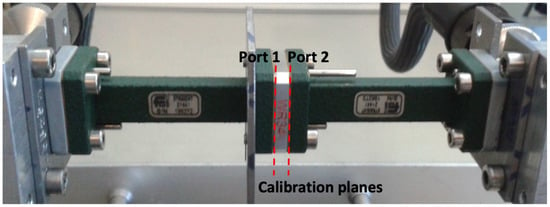
Figure 6.
Measurement setup.
It is well known that this procedure is quite effective when a single-mode operation can be exploited and the transmission curves present a significant peak. This can be generally emphasized by exploiting two irises [32]. Unfortunately, the high relative permittivity of the Zetamix samples on one side and the non-perfect dimensions of the samples on the other make the cited procedure much more complex. The measured curves, reported in Figure 7, present indeed different minima/peaks. They are related to the excitation of the higher-order modes (, with m = 2, 3…) in the loaded region. Moreover, the set of sample curves exhibits excellent dispersion due to dimensional variability. Despite these considerations, it would be possible to fix the relative permittivity to a value of around 7.6 with a dielectric loss tangent .
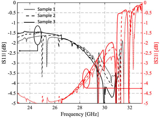
Figure 7.
Measured reflection and transmission coefficient of the three samples manufactured with the setup suggested by Nanoe and considering 100% infill. The curves in black refer to the reflection coefficient, while those in red show the transmission coefficient.
To target a relative permittivity close to , the guidelines provided by Nanoe were followed. In particular, in [30] a plot showing the variation of the equivalent versus the material porosity suggests setting the infill density to approximately 90%. This choice was combined with a tuning of the printing parameters (nozzle temperature, bed temperature, and speed), as reported in Table 1, to ensure both electromagnetic performance and successful manufacturability of the entire structure. The printing temperature was set to 285 °C with a heated bed temperature of 110 °C for proper adhesion. The extrusion width was 0.4 mm, with a layer height of 0.2 mm and a first layer height of 0.4 mm to enhance the foundation’s stability. To ensure uniform dielectric density and minimize inhomogeneities, an infill density of 90% with a gyroid pattern was used, providing consistent internal support and an optimized weight-to-strength ratio. A flow rate of 100% was maintained to minimize under-extrusion and ensure consistent density throughout the printed elements. The first layer was printed at 7 mm/s for better adhesion, while the subsequent layers were printed at 17 mm/s. To maintain a stable thermal environment, cooling was completely disabled (i.e., 0% fan speed). In addition, a brim of 12 lines was used to enhance bed adhesion and prevent warping.
One of the three samples obtained with this printer setup is shown in Figure 5b, and their sizes are summarized in Table 3. As can be seen in Figure 5b, this sample is less uniform than the one in Figure 5a. However, the size of the different bricks is more stable, as shown in Table 3, even if it is slightly lower than the waveguide dimensions.

Table 3.
Dimensions of the samples manufactured with the defined setup.
The results of the brick measurements are reported in Figure 8, where the frequency behavior of the reflection coefficient and the transmission coefficient is plotted. In this case, the set of blocks exhibits good repeatability, and the spikes due to higher-order mode resonances are less pronounced. The samples’ relative permittivity is confirmed to be around 5.9, which is very close to the desired value, while .
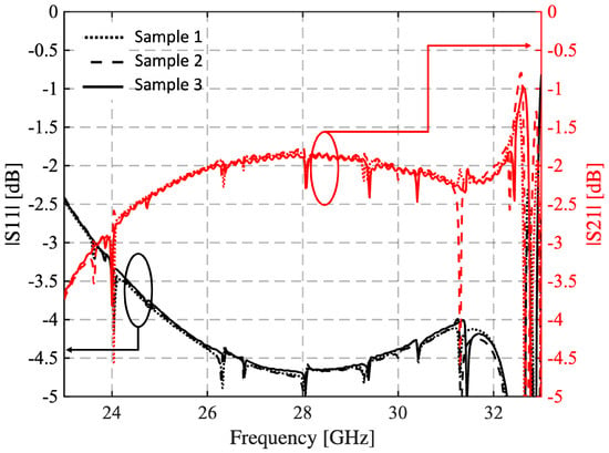
Figure 8.
Measured reflection and transmission coefficient of the three samples manufactured with the defined setup. The black curves refer to the reflection coefficient, while those in red show the transmission coefficient.
3. Reflectarray Antenna Design and Experimental Validation
3.1. UC Performance
In the previous section, the optimisation process and the results of the experimental characterisation of the material that led to the definition of the unit cell parameters were described. The final values for the UC geometrical parameters are: mm, mm, and mm, while the diameter of the cylindrical resonator, d, is varied in the range of to ensure the UC manufacturing still keeping a good range of variation for the phase of . The design frequency is GHz, and the UC performance is tested over the band 28 GHz–31 GHz.
Since the experimental characterization of the material returns a value for equal to none of those considered in the UC optimization process, its Floquet analysis was carried out one more time, and the plots in Figure 9 were obtained. They show the phase and magnitude of the reflection coefficient versus d for different angles of incidence and several frequencies in the band of interest. As expected, the phase response exhibits a smooth and monotonic variation with increasing diameter d, providing a wide phase tuning range. At the design frequency, the phase range covers , which is sufficient for the scope of the work, as already highlighted. Moreover, the phase curves corresponding to different incidence angles are nearly parallel, indicating a weak dependence on the angle of incidence. As concerns the magnitude , it remains above dB throughout the d variation range, indicating high reflection efficiency. Furthermore, the curves exhibit a consistent trend across all the frequencies evaluated, revealing the wide-band behavior of the UC. This frequency-independent response highlights the robustness of the design, ensuring stable performance over a broad operational bandwidth.
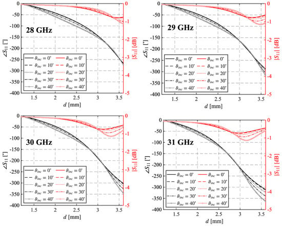
Figure 9.
Phase and magnitude of the reflection coefficient as a function of the diameter d for different frequencies computed for many angles of arrival.
3.2. RA Design and Experimental Characterization
Using the unit cell described above, a reflectarray operating at the center frequency has been designed.
In Figure 10a, the reflectarray geometry with the adopted coordinate system is sketched. The reflecting squared surface consists of UCs and has a side at . The RA is configured in an offset arrangement and the feeder is the circular horn introduced in [33], whose radiation pattern can be modeled as a function of with , and is located at a focal distance of 168 mm from the center of the RA. Both the incidence and the direction of maximum radiation are in the vertical plane (the plane in the coordinate system in Figure 10a). The incidence is characterized by angles , while the reflectarray is designed to point the reflected field in a direction characterized by and .
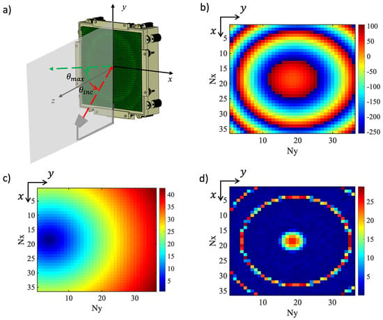
Figure 10.
(a) Sketch of the RA geometry with the coordinate system superimposed. (b) Required phase delay distribution for the designed RA at GHz. (c) Incidence angle map across the RA surface with respect to its normal vector. (d) Phase error map showing the residual discrepancies between the ideal and implemented phase distribution at GHz.
The required phase delay distribution is plotted in Figure 10b, calculated to compensate for the phase of the incident field on the RA surface, represented in Figure 10c. The phase error distribution, illustrated in Figure 10d, highlights the residual deviations between the required phase response and the one provided by the unit cell, which does not cover the entire range of , as already pointed out. From this, it emerges that the error introduced in the phase delay is, for most of the unit cell, lower than , and also in the worst case it is never larger than , and this confirms the proper design of the unit cell.
First, the RA was numerically analyzed using the time-domain solver of CST Microwave Studio™. A prototype was then manufactured and experimentally characterized. Figure 11 shows the manufactured RA, mounted inside the anechoic chamber at Politecnico di Torino, where the measurements were conducted. The antenna was tested in the spherical near-field test range, using an angular sampling of in both azimuth and elevation [34]. The near-field data were post-processed to obtain the far-field radiation patterns. The gain was estimated by comparing the measured field level of the reflectarray with that of a reference standard horn. The aperture efficiency was then computed as the ratio between the measured gain and the theoretical directivity of a uniformly illuminated aperture having the same physical size. The inset in Figure 11 displays a photo of the front view of the prototype.
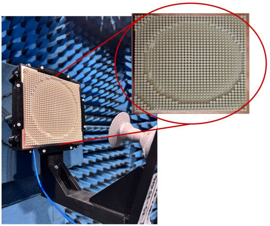
Figure 11.
Setup of the manufactured RA prototype in the anechoic chamber. Inset: front view of the RA prototype.
The principal results of the numerical and experimental characterization are summarized in Figure 12 and Figure 13. Figure 12 shows the normalized radiation patterns in the E-plane (vertical plane) of the manufactured RA at 28 GHz–31 GHz, compared with those obtained with the RA full-wave analysis. The main beam is successfully steered towards , as intended by the design specifications. The main lobe exhibits excellent agreement between measurements and simulations, validating the RA’s ability to achieve precise beam pointing. Minimal discrepancies can be observed, which can be primarily attributed to two factors: fabrication tolerances inherent in the 3D printing process and alignment inaccuracies during the measurement setup in the anechoic chamber. Despite these slight variations, the RA maintains a stable radiation pattern across the frequency range, demonstrating good frequency robustness with well-controlled side lobe levels (SLLs), consistently lower than −20 dB.
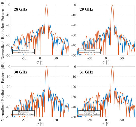
Figure 12.
Simulated and measured co-polar radiation patterns in the E-plane.
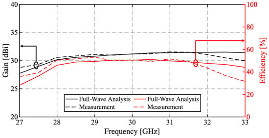
Figure 13.
Measured and simulated gain and aperture efficiency variation as a function of frequency.
Figure 13 shows the measured and simulated gain and aperture efficiency of the RA as functions of the frequency. The measured gain has a peak value of 31.6 dBi at 31 GHz. It exhibits a remarkably flat response within the considered frequency range of 28 GHz to 31 GHz, with a measured 1-dB bandwidth of 16%, highlighting the robust broadband performance of the RA. The measured aperture efficiency exceeds 50% throughout the band, reaching a maximum of 53.2% at 29 GHz.
Overall, the results validate the effectiveness of the proposed design approach, demonstrating excellent agreement between full-wave simulations and experimental data. Moreover, they confirm that the use of a material such as Zetamix , with a tunable value of equivalent introduces an additional degree of freedom that can be used to optimize the performance of the device to be built, as in this case the RA.
Finally, Table 4 summarizes the comparison with 3D-printed dielectric reflectarrays reported in the literature, spanning from 2017 to 2024 [24,25,26,27,28]. It can be observed that the solution in [28] exhibits the highest aperture efficiency. However, the RA is quite small and is center-fed, while the proposed one has an offset feed. The designs in [24,25,26,27] show dimensions larger than those in [28] with efficiencies below 35%. In contrast, the proposed RA combines a larger electrical aperture of with a compact thickness of and a measured gain above dBi in the 1-dB gain bandwidth, while maintaining an aperture efficiency above 50%. Regarding the concerns with the 1-dB gain bandwidth, the largest one is in [25] and comes at the cost of a lower gain. The solutions in [26,28] show a slightly larger bandwidth compared with the proposed RA, but it must be taken into account that their reflectarrays’ dimensions, and therefore the gain, are much smaller (see columns 4 and 6 of Table 4). This performance can be explained by considering that the unit cell presents an almost linear variation of the phase delay versus its geometrical dimensions, a significantly reduced sensitivity with respect to the incidence angle of the impinging plane wave, and a uniform global phase shift with the frequency (i.e., the phase delay curves versus d are almost parallel for different frequencies). These properties enable us to achieve a reasonable efficiency and bandwidth, albeit with the requirement for high gain and offset-center illumination.

Table 4.
Comparison with recent state-of-the-art Ka-band dielectric reflectarrays fabricated via additive manufacturing.
4. Conclusions
This work focuses on the design, manufacturing, and experimental validation of a fully dielectric RA operating in the Ka band that exploits Zetamix 7.5 ceramic-based material through additive manufacturing. The RA uses cylindrical UCs, with optimized 3D printing parameters tailored to address the unique challenges posed by the high-permittivity material. The possibility to control the value of the equivalent relative permittivity by varying the infill during the manufacturing process allows us to consider as a further degree of freedom that can be exploited to optimize the unit cell and consequently the RA performance. The excellent agreement between the full-wave analysis and the experimental results confirms the effectiveness of the proposed approach.
Author Contributions
The individual contributions of the authors to the realization of this work are as follows: Conceptualization, M.B., A.M., M.L., G.A., A.F. and P.P.; methodology, M.B., A.M., M.L., G.A., A.F. and P.P.; software, M.B., A.M., M.L. and G.A.; validation, M.B., A.M., M.L., G.A., A.F. and P.P.; formal analysis, M.B., A.M., M.L., G.A., A.F. and P.P.; investigation, M.B., A.M., M.L., G.A., A.F. and P.P.; resources, A.F. and P.P.; writing—original draft preparation, M.B., M.L. and G.A.; writing—review and editing, A.F. and P.P.; visualization, M.B.; supervision, P.P.; project administration, A.F. and P.P.; funding acquisition, A.F. and P.P. All authors have read and agreed to the published version of the manuscript.
Funding
This research received no external funding.
Institutional Review Board Statement
Not applicable.
Informed Consent Statement
Not applicable.
Data Availability Statement
All data generated or analysed during this study are included in this article.
Acknowledgments
The authors express their gratitude to Gianluca Dassano, for performing the experimental characterization of the reflectarray.
Conflicts of Interest
The authors declare no conflict of interest.
References
- Huang, J.; Encinar, J.A. Reflectarray Antennas; John Wiley & Sons: Hoboken, NJ, USA, 2007. [Google Scholar]
- Nayeri, P.; Yang, F.; Elsherbeni, A.Z. Reflectarray Antennas: Theory, Designs and Applications; John Wiley & Sons: Hoboken, NJ, USA, 2018. [Google Scholar]
- Pozar, D.; Targonski, S.; Syrigos, H. Design of millimeter wave microstrip reflectarrays. IEEE Trans. Antennas Propag. 1997, 45, 287–296. [Google Scholar] [CrossRef]
- Encinar, J. Design of two-layer printed reflectarrays using patches of variable size. IEEE Trans. Antennas Propag. 2001, 49, 1403–1410. [Google Scholar] [CrossRef]
- Kocia, C.; Hum, S.V. Design of an Optically Transparent Reflectarray for Solar Applications Using Indium Tin Oxide. IEEE Trans. Antennas Propag. 2016, 64, 2884–2893. [Google Scholar] [CrossRef]
- An, W.; Xu, S.; Yang, F. A Metal-Only Reflectarray Antenna Using Slot-Type Elements. IEEE Antennas Wirel. Propag. Lett. 2014, 13, 1553–1556. [Google Scholar] [CrossRef]
- Deng, R.; Yang, F.; Xu, S.; Li, M. A Low-Cost Metal-Only Reflectarray Using Modified Slot-Type Phoenix Element with 360° Phase Coverage. IEEE Trans. Antennas Propag. 2016, 64, 1556–1560. [Google Scholar] [CrossRef]
- Carluccio, G.; Mazzinghi, A.; Freni, A. Design and Manufacture of Cosecant-Squared Complementary Reflectarrays for Low-Cost Applications. IEEE Trans. Antennas Propag. 2017, 65, 5220–5227. [Google Scholar] [CrossRef]
- He, Y.; Gao, Z.; Jia, D.; Zhang, W.; Du, B.; Chen, Z.N. Dielectric Metamaterial-Based Impedance-Matched Elements for Broadband Reflectarray. IEEE Trans. Antennas Propag. 2017, 65, 7019–7028. [Google Scholar] [CrossRef]
- Da, W.M.; Li, B.; Zhou, Y.; Guo, D.L.; Liu, Y.; Wei, F.; Lv, X. Design and measurement of a 220 GHz wideband 3-D printed dielectric reflectarray. IIEEE Antennas Wirel. Propag. Lett. 2018, 17, 2094–2098. [Google Scholar]
- Mei, P.; Zhang, S.; Pedersen, G.F. A Wideband 3-D Printed Reflectarray Antenna With Mechanically Reconfigurable Polarization. IEEE Antennas Wirel. Propag. Lett. 2020, 19, 1798–1802. [Google Scholar] [CrossRef]
- Singh, A.; Andrello, M.; Einarsson, E.; Jornet, N.T.J.M. Design and Operation of a Smart Graphene–Metal Hybrid Reflectarray at THz Frequencies. In Proceedings of the 14th European Conference on Antennas and Propagation (EuCAP), Copenhagen, Denmark, 15–20 March 2020; pp. 1–5. [Google Scholar] [CrossRef]
- Chen, B.; Wu, B.; Zu, H.R.; Hou, J.Q.; Su, T. Experimental demonstration of high optically transparent reflectarrays using fine metal line structure. IEEE Trans. Antennas Propag. 2022, 70, 10504–10511. [Google Scholar] [CrossRef]
- Massaccesi, A.; Bertana, V.; Beccaria, M.; Marasso, S.L.; Cocuzza, M.; Dassano, G.; Pirinoli, P. Three-Dimensional-Printed Wideband Perforated Dielectric-Only Reflectarray in Ka-Band. IEEE Trans. Antennas Propag. 2023, 71, 7848–7859. [Google Scholar] [CrossRef]
- Jiang, P.; Jiang, W.; Hu, W.; Gong, S. A Mesh-Type Shared-Aperture Dual-Band Circularly Polarized Transmit- Reflect-Array Antenna. IEEE Trans. Antennas Propag. 2023, 71, 1590–1601. [Google Scholar] [CrossRef]
- Massaccesi, A.; Beccaria, M.; Bertana, V.; Marasso, S.L.; Cocuzza, M.; Dassano, G.; Pirinoli, P. 3D-printed wideband reflectarray antennas with mechanical beam-steering. Int. J. Microw. Wirel. Technol. 2023, 16, 21–29. [Google Scholar] [CrossRef]
- Sofokleous, P.; Paz, E.; Herraiz-Martínez, F.J. Design and Manufacturing of Dielectric Resonators via 3D Printing of Composite Polymer/Ceramic Filaments. Polymers 2024, 16, 2589. [Google Scholar] [CrossRef] [PubMed]
- Li, S.; Izquierdo, B.S.; Gao, S.; Chen, Z. Analysis of 3D Printed Dielectric Resonator Antenna Arrays for Millimeter-Wave 5G Applications. Appl. Sci. 2024, 14, 9886. [Google Scholar] [CrossRef]
- Hehenberger, S.P.; Caizzone, S.; Yarovoy, A.G. Additive Manufacturing of Linear Continuous Permittivity Profiles and Their Application to Cylindrical Dielectric Resonator Antennas. IEEE Open J. Antennas Propag. 2023, 4, 373–382. [Google Scholar] [CrossRef]
- Marrocco, V.; Basile, V.; Fassi, I.; Grande, M.; Laneve, D.; Prudenzano, F.; D’Orazio, A. Dielectric Resonant Antennas via Additive Manufacturing for 5G Communications. In Proceedings of the 2019 PhotonIcs & Electromagnetics Research Symposium-Spring (PIERS-Spring), Rome, Italy, 17–20 June 2019; pp. 174–180. [Google Scholar] [CrossRef]
- van Hoang, T.Q.; Bertrand, M.; Vandelle, E.; Loiseaux, B. Low-Profile Highly Directive 2D-Beam-Steering Antenna in Ka-band with 3D-printed All-dielectric Sub-wavelength Deflectors. In Proceedings of the 52nd European Microwave Conference (EuMC), Milan, Italy, 27–29 September 2022; pp. 852–855. [Google Scholar] [CrossRef]
- Malfajani, R.S.; Damansabz, R.; Bodkhe, S.; Therriault, D.; Laurin, J.-J.; Sharawi, M.S. 3-D-Printed Encapsulated Dielectric Resonator Antennas With Large Operation Frequency Ratio for Future Wireless Communications. IEEE Open J. Antennas Propag. 2024, 5, 1351–1364. [Google Scholar] [CrossRef]
- Nadeem, A.; Chatzichristodoulou, D.; Shoaib, N.; Vryonides, P.; Nikolaou, S. Gain Enhancement of a 5G mmWave 2 × 2 Antenna Array Using a 3D Printed Hemispherical Lens. In Proceedings of the 2023 IEEE International Symposium on Antennas and Propagation and USNC-URSI Radio Science Meeting (USNC-URSI), Portland, OR, USA, 23–28 July 2023; pp. 1697–1698. [Google Scholar] [CrossRef]
- Zhang, S. Three-dimensional printed millimetre wave dielectric resonator reflectarray. IET Microw. Antennas Propag. 2017, 11, 2005–2009. [Google Scholar] [CrossRef]
- Sun, Y.-X.; Leung, K.W. Millimeter-Wave Substrate-Based Dielectric Reflectarray. IEEE Antennas Wireless Propag. Lett. 2018, 17, 2329–2333. [Google Scholar] [CrossRef]
- Cui, Y.; Bahr, R.; Nauroze, S.A.; Cheng, T.; Almoneef, T.S.; Tentzeris, M.M. 3D Printed “Kirigami”-Inspired Deployable Bi-Focal Beam-Scanning Dielectric Reflectarray Antenna for mm-Wave Applications. IEEE Trans. Antennas Propag. 2022, 70, 7683–7690. [Google Scholar] [CrossRef]
- Chekkar, W.; Lanteri, J.; Malvaux, T.; Sourice, J.; Lizzi, L.; Migliaccio, C.; Ferrero, F. A 3D-Printed Bi-Material Bragg-Based Reflectarray Antenna. Sensors 2024, 24, 6512. [Google Scholar] [CrossRef]
- Tiwari, S.; Singh, A.K.; Dubey, A. Additively Manufactured Dielectric Reflectarray Antenna for Millimeter-Wave Satellite Communication. IEEE Antennas Wirel. Propag. Lett. 2024, 23, 1276–1280. [Google Scholar] [CrossRef]
- Available online: https://zetamix.fr/produit/filament-epsilon/ (accessed on 2 March 2025).
- Available online: https://zetamix.fr/wp-content/uploads/2024/09/guideline-epsilon.pdf (accessed on 15 February 2025).
- Available online: https://www.raise3d.com/pro3-series/ (accessed on 15 February 2025).
- Lumia, M.; Addamo, G.; Virone, G.; Peverini, O.A.; Paonessa, F.; Rabitsch, J.; Mele, M.; Calignano, F.; Manfredi, D.; Bouzekri, O. RF Characterization of 3D-Printed Dielectric Materials. In Proceedings of the 2023 IEEE Conference on Antenna Measurements and Applications (CAMA), Genoa, Italy, 15–17 November 2023; pp. 808–813. [Google Scholar] [CrossRef]
- Beccaria, M.; Addamo, G.; Orefice, M.; Peverini, O.; Manfredi, D.; Calignano, F.; Virone, G.; Pirinoli, P. Enhanced Efficiency and Reduced Side Lobe Level Convex Conformal Reflectarray. Appl. Sci. 2021, 11, 9893. [Google Scholar] [CrossRef]
- Available online: https://lace.polito.it/ (accessed on 23 August 2025).
Disclaimer/Publisher’s Note: The statements, opinions and data contained in all publications are solely those of the individual author(s) and contributor(s) and not of MDPI and/or the editor(s). MDPI and/or the editor(s) disclaim responsibility for any injury to people or property resulting from any ideas, methods, instructions or products referred to in the content. |
© 2025 by the authors. Licensee MDPI, Basel, Switzerland. This article is an open access article distributed under the terms and conditions of the Creative Commons Attribution (CC BY) license (https://creativecommons.org/licenses/by/4.0/).