4.1. Design of Data Transmission Scheme for Digital Twin System of Welding Robotic Arm
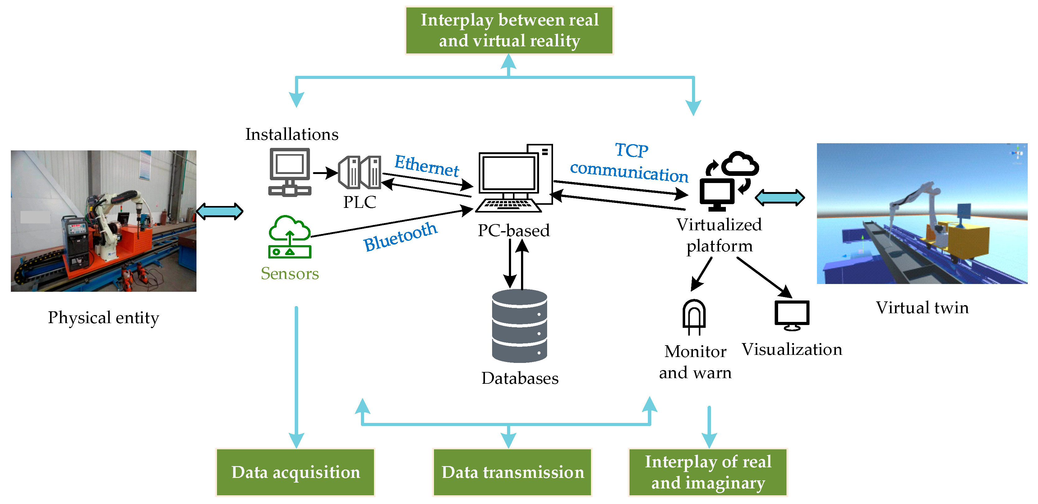
The data connection between the welding robotic arm digital twin system and the physical entity includes data acquisition, data transmission, virtual reflection of the real robotic arm, and real control of the virtual model. The specific process is shown in
Figure 23.
(1) Data Acquisition: Data acquisition refers to the organization and collection of the data of the welding robot arm workstation in the actual production process. The real-time acquisition of data is realized through a variety of data acquisition terminals, mainly based on sensors. According to the different types of actual on-site equipment, the appropriate communication protocol between the equipment is selected, such as Modbus, TCP, Ethernet, Bluetooth, or Wi-Fi.
(2) Data transmission: Data transmission is a key link in the realization of digital twins, and it is the basis that enables the virtual end to reflect the physical end. The data transmission part of the welding robot arm digital twin system involves two transmission processes. One is the data transmission between the digital twin system and the physical entity, and the other is the data transmission between the algorithm software on the PC side and the digital twin system.
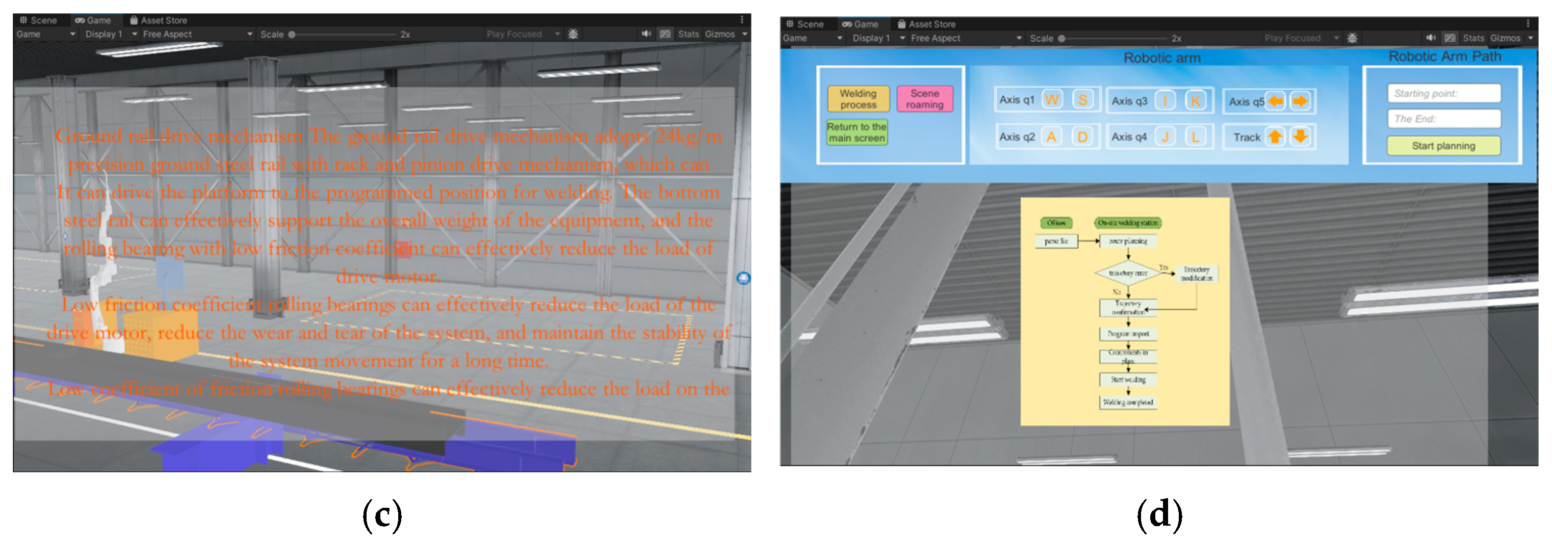
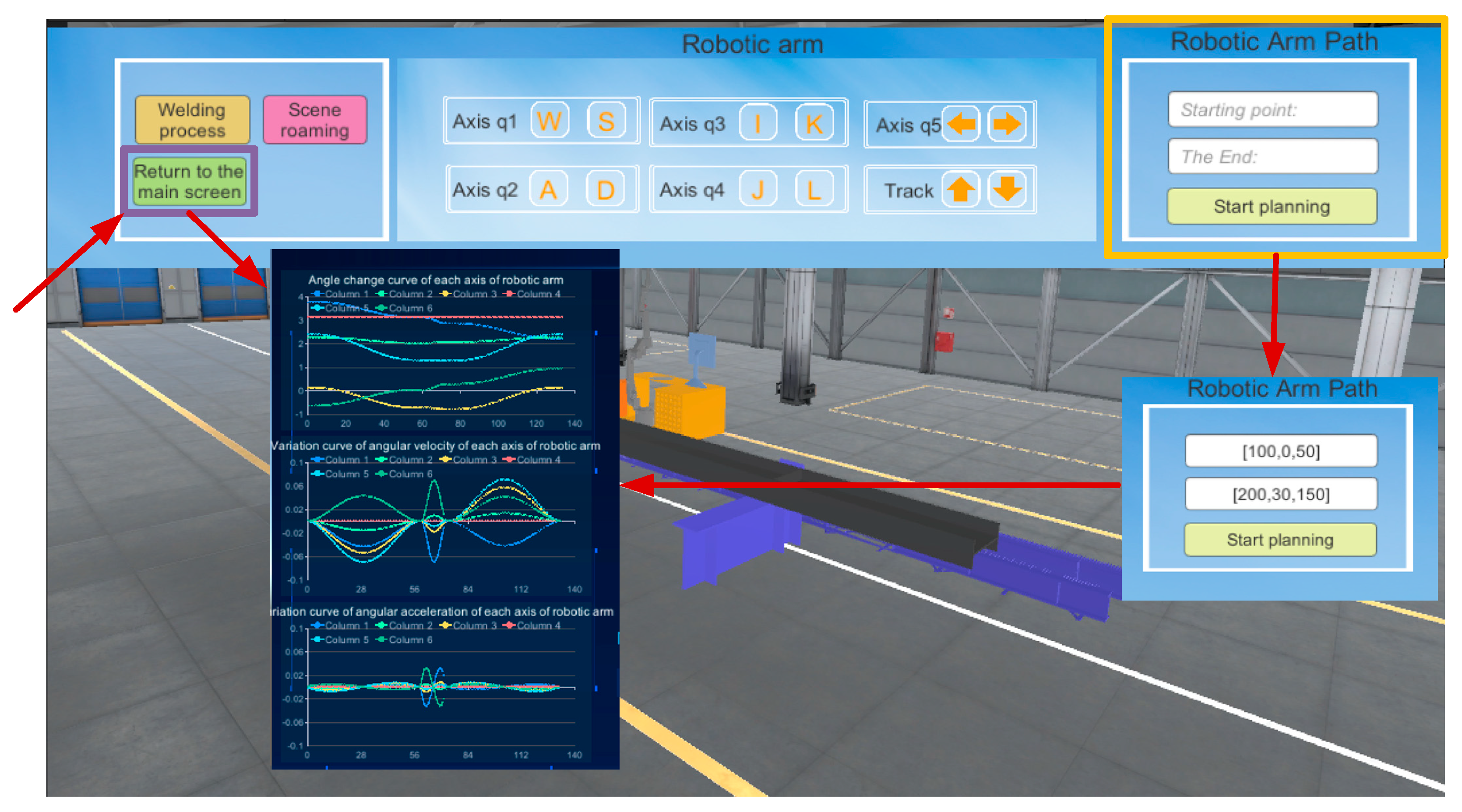
(3) Virtual image of real robotic arm: The data collected by the field equipment is transferred to the digital twin through various communication methods, and then the actions of each link of the welding robotic arm workstation are accomplished according to the data types, including the traveling and stopping of the ground rail, the rotation of each joint of the robotic arm, and so on.
(4) Virtual control of the real robotic arm: The ability of the welding robotic arm digital twin system to control the physical entity is key for realizing its remote-control operations. The data transmission channel will regulate the commands or information output to the physical entity, so as to control the field equipment to complete the specified command. The realization of virtual control meets the requirements of saving resources, and at the same time, prevents casualties due to operational errors, to ensure that the production site is safe and reliable.
Data transmission is the key to enabling the welding robotic arm digital twin system to connect to the physical entity. The data transmission between the virtual end and the physical entity needs to meet the following conditions:
(1) Real-Time Transmission: Real-time transmission can ensure that the system accepts the data from the physical end in real time, to ensure that the welding robotic arm’s physical entity sends the virtual twin real-time feedback. Real-time feedback between the virtual and real robotic arm can enable the digital twin system to quickly reflect the changes in the operating status of the equipment, and adjust the production strategy and operating parameters in a timely manner to optimize production efficiency and quality.
(2) Accuracy: The accuracy of data transmission directly affects the reliability of the welding robot arm digital twin system. This requires the actual collection of data to ensure that the data is accurate and complete, while ensuring that the data is not lost in the transmission process and is not affected by noise.
4.2. Welding Robot Arm Data Acquisition and Transmission
The entire welding process is a collaborative effort of mechanical and electrical systems, involving multiple data types. The process of data acquisition and transmission involves various layers, such as a physical layer, virtual layer, and data layer. Before collecting data for data type analysis, the following five points should be considered (
Figure 24) [
15].
(1) Data compatibility: Data compatibility refers to different communication methods in the transmission of data. The process of data formatting may be different, so the collection of data should be fully considered before the data is collected to ensure that it is compatible with the current system. Data format mismatch should be avoided to prevent data loss or failure to parse the situation.
(2) Data accuracy: First, the accuracy of each data type should be determined before data transmission. The required accuracy, compression, or streamlining of the data should be within the allowable range to avoid the problems of slow operation or system overload.
(3) Encrypted data security: Some of the data in the digital twin system may involve corporate secrets or private personal data. Analyze whether there is any private data before data transmission, use a separate data transmission channel for confidential data, and at the same time, through encryption of data, restrict access authorization. This is to ensure that the data is transmitted securely and privately.
(4) Data processing and analysis needs: In the digital twin system, different data types represent different information, and before data collection, it is necessary to understand the use and needs of each data type, so as to involve appropriate data processing processes. For example, depending on the frequency of data updates, some data types need to be analyzed and processed in real time, while certain types only need to be updated periodically or stored for backup.
(5) Network and bandwidth optimization: When transferring large amounts of data through the cloud or remote servers, network bandwidth requirements are extremely high. The frequency and magnitude of data transmission should be determined when categorizing the data, and data of the same frequency and magnitude can be transmitted together to reduce costs and improve efficiency.
By analyzing the workflow of the welding robot arm and combining the above requirements for data classification, the data information involved is divided into the following categories, as shown in
Figure 25.
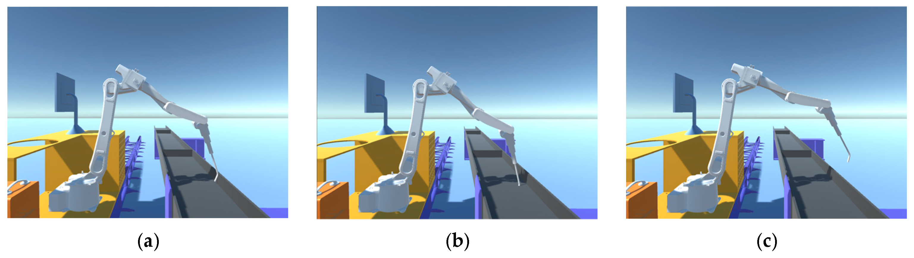
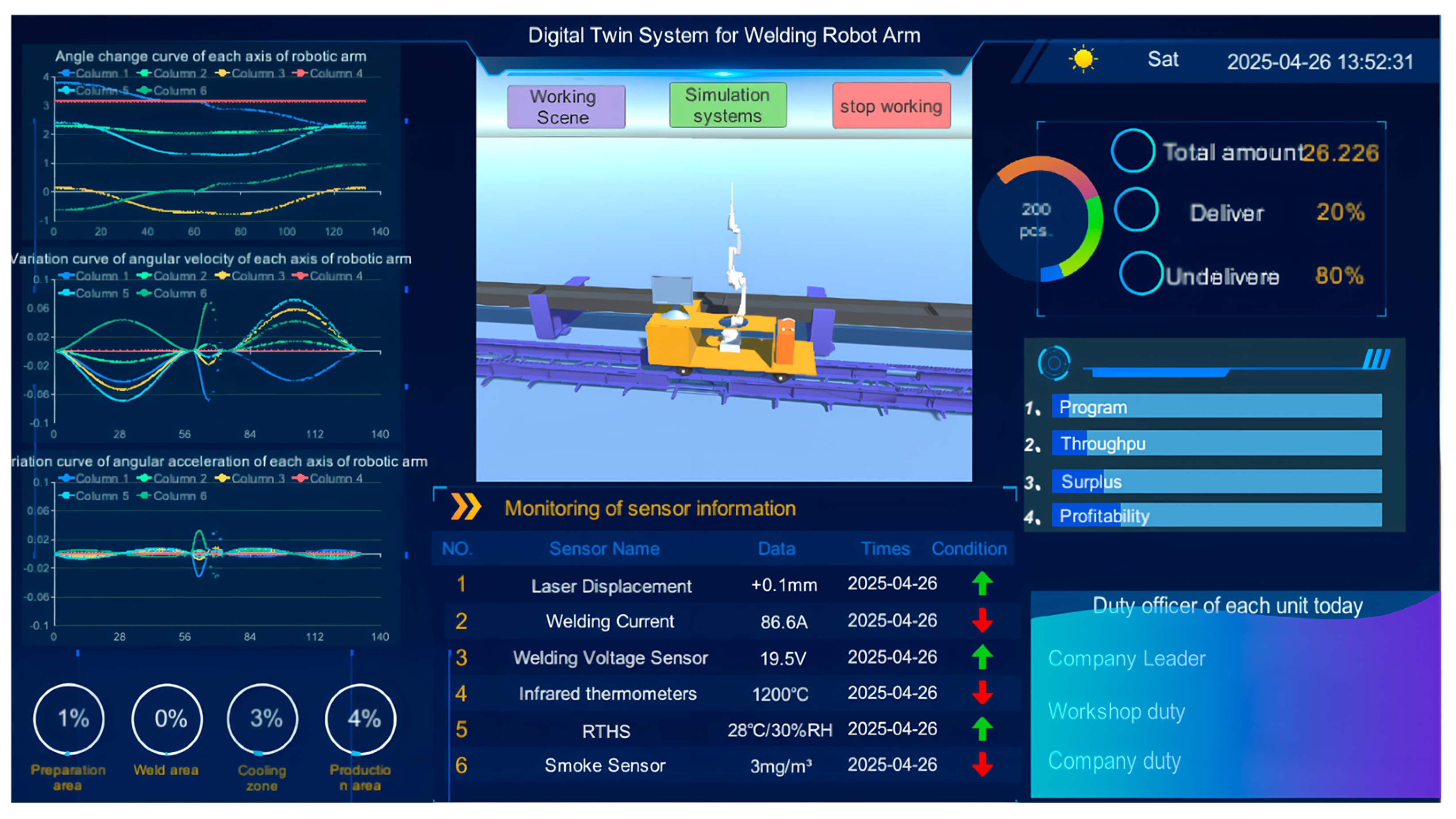
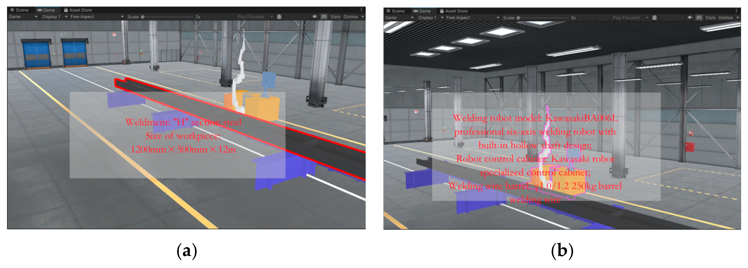
The welding process of “H” section steel components consists of the following steps: alignment, welding, and cooling. The use of different types of sensors ensures data acquisition for each step and visualization of the entire welding process. Position sensors are used to ensure that the “H” sections are correctly positioned before welding. Welding current, voltage, and temperature are monitored during the welding process. Current and voltage sensors are used to ensure that the welding parameters are within the set range, and temperature sensors are used to monitor the temperature of the weld point. In addition, temperature sensors are used to monitor the cooling rate. In terms of weld quality monitoring, the company currently uses manual ultrasonic flaw detection, so no sensors are placed in this area. Environmental sensors are also arranged throughout the whole workshop. Temperature and humidity sensors are used to ensure the welding environment is stable and prevent humidity from affecting the welding quality. Smoke sensors and flame sensors are used to prevent fires, protect personnel, and ensure equipment safety. Specific information is shown in
Table 5.
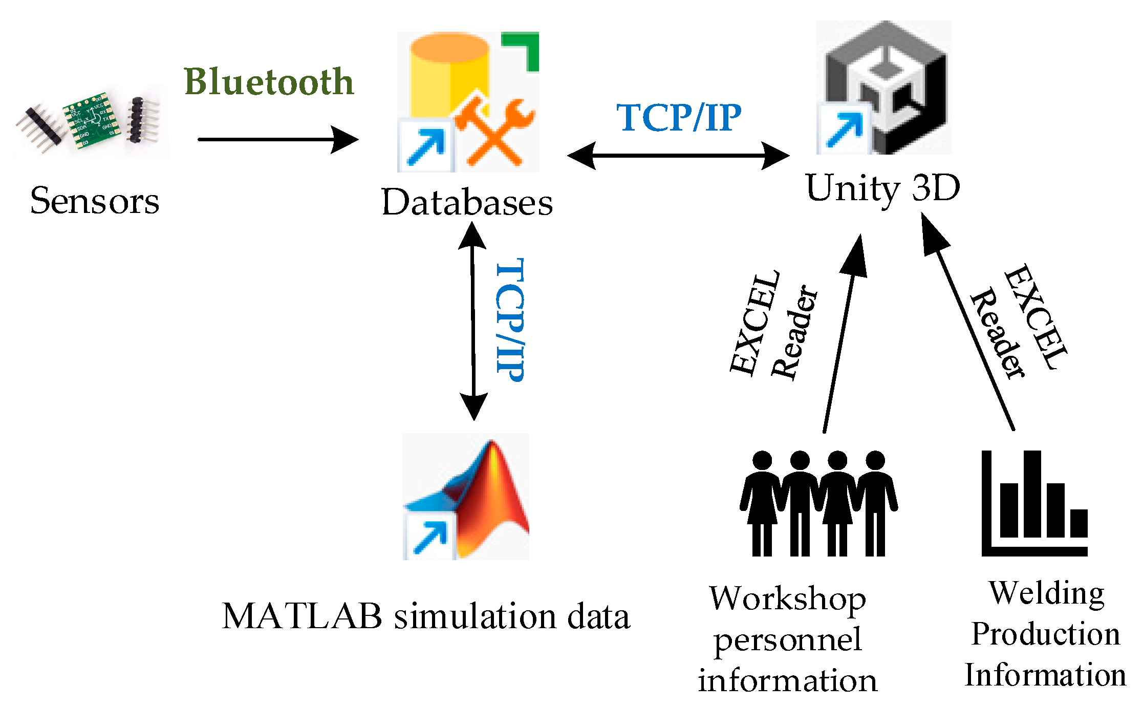
The data transmission routes and communication methods are shown in
Figure 26. The inclusion of data transmission between MATLAB and Unity3D in the data transmission network is because MATLAB serves as the platform for path planning of the welding robotic arm, and the path-planning data is directly simulated through Unity3D. This approach avoids the loss of manpower and financial resources that would otherwise occur when testing path planning on actual equipment.
In the development of the welding robotic arm digital twin system, Unity 3D, as a lightweight 3D development engine, can only be used as a visualization platform and does not have data storage capabilities. Therefore, during data collection and transmission, an intermediate medium is required for organizing, storing, and exchanging data. This medium is the database. Database systems support the storage of data types that fall into two broad categories: structured data and unstructured data. Database types in back-end development can be categorized into two types: relational and non-relational databases. All the data involved in the welding robot arm digital twin system is structured data, i.e., data stored in tabular form. Therefore, a relational database is chosen when selecting a database. Common database software includes the following: the Oracle database, MongoDB database, MySQL database, DB2 database, and SQL Server database. Considering the data type, the database needs to support data transfer with Unity 3D and MATLAB, so we finally choose the SQL Server database that can satisfy all data transfer [
16].
In terms of data transmission technology, we combine TCP/IP with Bluetooth communication. This is because parallel transmission of multi-source data is faster and has a higher data integration rate. It enhances real-time monitoring and dynamic response capabilities, enabling synchronous collection of multidimensional data and rapid alerts for abnormal conditions, such as synchronous monitoring of current and welding gun temperature during welding, thereby reducing the rate of missed equipment abnormalities. It optimizes production efficiency and process stability, and supports dynamic optimization of welding parameters and coordinated scheduling of multiple devices, improving equipment operational efficiency. Additionally, it enhances system scalability and cost control capabilities, enabling flexible integration of heterogeneous devices and data-driven predictive maintenance, thereby reducing equipment integration and maintenance costs.
(1) TCP/IP Communication Protocol
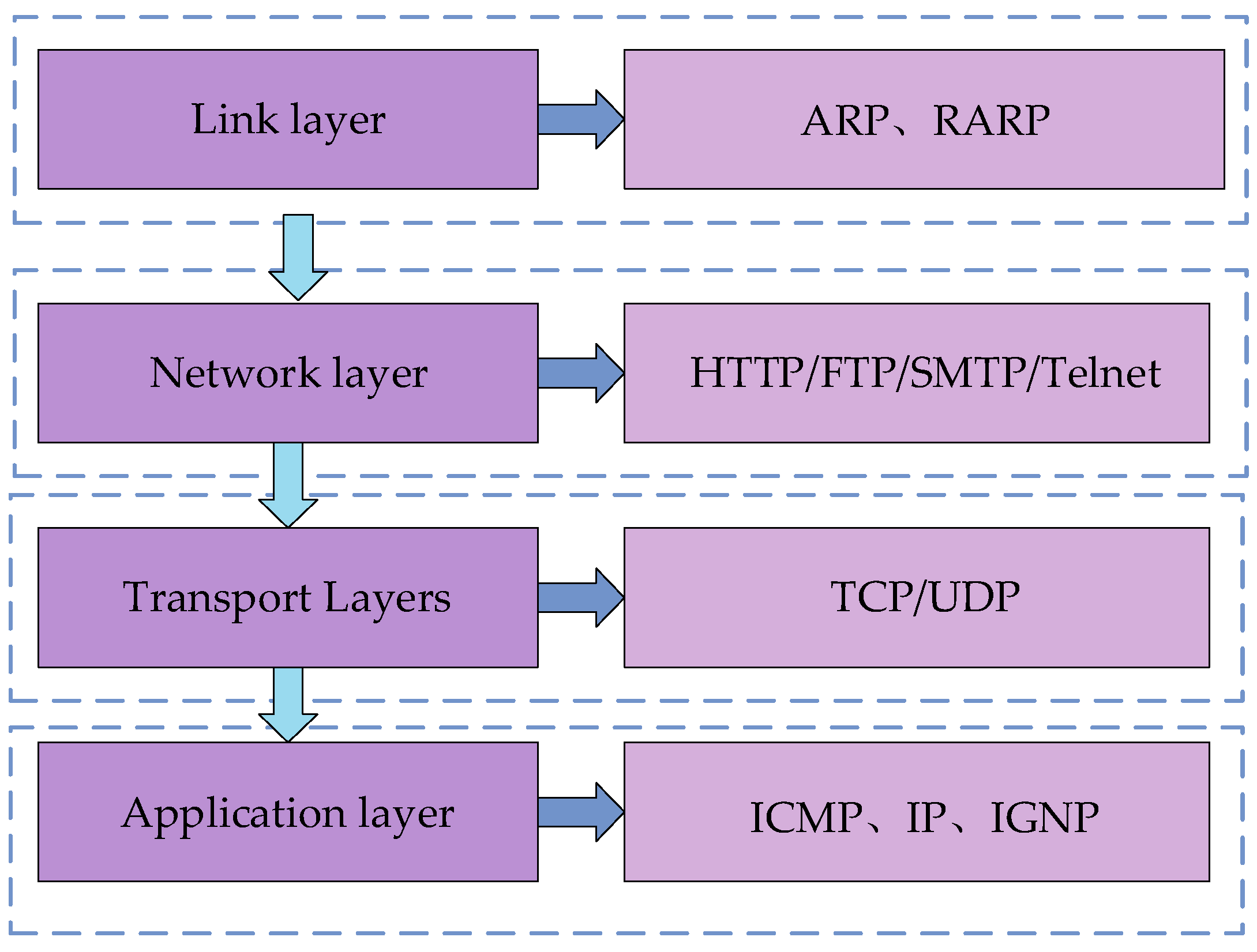
The TCP/IP (Transmission Control Protocol/Internet Protocol) communication protocol is the basis for communication on the Internet and most LANs. The TCP/IP communication model consists of four layers: the application layer, transport layer, network layer, and link layer. The various protocols in the TCP/IP model are divided into these four layers according to the functions they fulfill. The transmission and processing of data are then realized through the interfaces of the two adjacent layers. As shown in
Figure 27, the model of the TCP/IP communication protocol and the protocols contained in each layer are illustrated. The application layer, which is built on top of TCP or UDP, is used to define how applications exchange data and communicate; the reliability of the data transmission and whether the data reaches the receiving layer in the correct order is ensured by the transport layer. The IP address of the destination determines the next path of the transmitted data, which is then forwarded by the network layer. A hardware device—a router—is involved in this process. It can determine the transmission path based on the IP address and then transmit the data to the receiving host through the link layer, thus enabling the transmission of packets across different networks. The link layer refers to the hardware that handles the connection to the network.
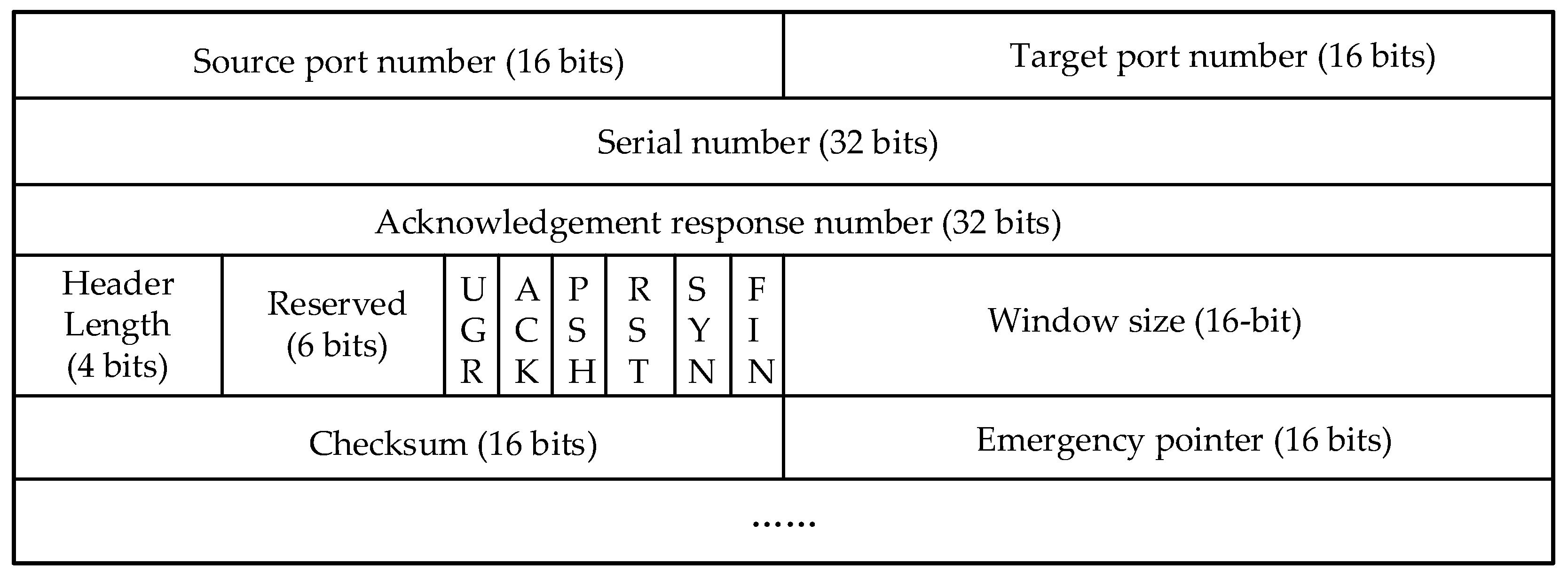
The TCP header format contains key information used to establish, maintain, and terminate connections as well as to ensure the reliability of TCP communications.
Port numbers, serial numbers, acknowledgement numbers, control flags, and window sizes are used to ensure reliable data transmission, traffic control, and connection management. Check digits are used for error detection, and emergency pointers are used to handle emergencies. Together, this information ensures a clear connection orientation, and the TCP header format is shown in
Figure 28.
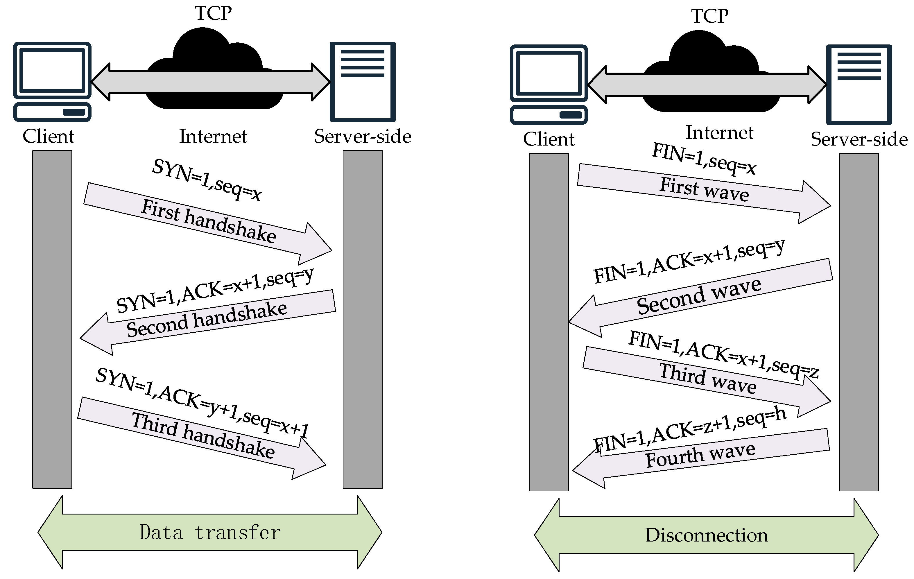
The realization of the TCP protocol communication process includes “three handshakes” and “four handshakes”. The former is used to establish a connection, and the latter is used to terminate it. The steps to establish a connection are as follows:
(1) The first handshake: The client will send a special TCP segment to the server. This TCP segment not only carries the client that identifies the beginning of the data flow to the beginning of the sequence number (INS), but also initiates a request for the SYN flag bit, that is, the synchronization flag bit. The initial sequence number is seq = x, where x is a randomly generated value to ensure that the sequence number of each connection is unique, thus avoiding duplication or confusion of old connections.
(2) Second handshake: When the server receives the SYN segment from the client, if it decides to accept the connection request, it responds with a TCP segment that has both the SYN and ACK flag bits set. This response segment not only contains the server’s own initial sequence number (ISN), which identifies the starting point of its data stream, but also acknowledges the ISN previously sent by the client, i.e., ACK = x + 1, indicating the next sequence number expected to be received. In this segment, the SYN flag bit is likewise set to 1, indicating that the server is also in a synchronized state, while seq=y is the initial sequence number randomly generated by the server, ensuring the uniqueness and security of the connection.
(3) Third handshake: When the client receives the SYN-ACK segment from the server, it sends a TCP segment with the ACK flag bit as a final confirmation. This segment contains an acknowledgement of the server’s sequence number (ACK=y+1), indicating that the client has successfully received the server’s initial sequence number and is ready to start receiving data. At this point, the three-handshake process of the TCP connection is complete, and the two parties have established a reliable communication channel and can begin formal data transmission.
Since TCP connections are full-duplex, i.e., data can be transmitted in both directions at the same time, each direction needs to be closed independently when disconnecting. This bidirectional closure mechanism results in a four-wave process for disconnecting, as shown in
Figure 29.
(1) First wave: The client indicates completion of data transfer and decides to close the connection when it sends a TCP segment with a FIN flag bit (end flag) to the server.
(2) Second wave: When the server receives the TCP segment with the FIN segment sent by the client, it then responds with a TCP segment with the ACK flag bit, indicating that it has confirmed that the client is ready to close the connection request.
(3) Third wave: When the client completes all data transmission, it sends a TCP segment with the FIN flag bit to the server, indicating that all data transmission from the client has been completed.
(4) Fourth wave: When the server receives the FIN segment sent by the client, it sends the last TCP segment with an ACK segment and then closes the connection. The client will also close the connection immediately after receiving the last TCP segment. At this point, the “four waves” are completed, and TCP communication is completely terminated.
(2) Bluetooth communication
When collecting sensor data information, the Bluetooth module is selected to send the data information to the upper computer database. Similar to the TCP/IP communication protocol, the implementation of Bluetooth communication relies on the Bluetooth protocol stack (BPS). This protocol stack specifies how data transfer and communication between Bluetooth devices take place.
The Bluetooth protocol stack consists of multiple layers, each of which bears different functions and responsibilities, and the specific hierarchical structure and the contents contained in each layer are shown in
Figure 30 [
17,
18]. The application layer, as the top layer of the Bluetooth protocol stack, interacts directly with the application program interface (API) and provides functions such as file transfer, audio transmission, etc. The physical layer, as the bottom layer of the Bluetooth protocol stack, is responsible for radio-frequency data transmission by defining the wireless transmission rate, frequency, etc. The link layer is built between the application layer and the physical layer. The physical layer is the bottom layer of the Bluetooth stack, which is responsible for radio-frequency data transmission by defining the radio transmission rate, frequency, etc. The link layer is established between the application layer and the physical layer, which is responsible for transmitting and receiving data packets between layers. In addition, it also contains error detection and correction mechanisms, which can segment and reorganize the packets. The HC-05 Bluetooth module was finally selected by synthesizing the field equipment. This Bluetooth module is suitable for remote control, data logging applications, robotics, and monitoring systems. Based on the Bluetooth 2.0 protocol, it is able to support data transmission between two microcontrollers with serial communication capability, as well as control and manage other Bluetooth devices through the microcontroller.
(3) ExcelDataReader Library
Workshop operators, shift conditions, order profitability, and other related data are stored directly in the form of Excel tables in the host computer, so one can write C# scripts in Unity 3D to call the ExcelDataReader library to read Excel table information. The ExcelDataReader library is used to read Excel files, and it is open source. The NET library supports reading a variety of Excel file formats. It also provides a simple API to extract data from Excel files. Welding robot arm data stored in the Excel table format is in “.xls” format.
4.3. Validation of Data Transmission Results
(1) Data transfer between sensors and database
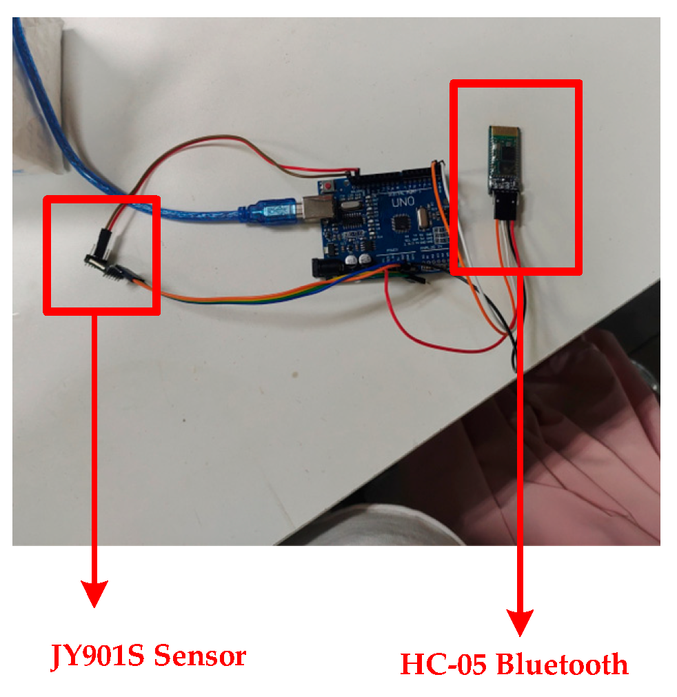
Take the JY901S sensor as an example to introduce the sensor and the data transmission in the database. The sensor is placed at the end of the robotic arm actuator, responsible for the collection of the angle at the end of the robotic arm execution, angular acceleration, and so on. Before the data collection, it is necessary to connect the sensor with the Bluetooth module with the help of an Arduino Uno development board, as shown in
Figure 31 and
Figure 32. Since the sensor cannot transmit the data to the PC alone, it is necessary to use a microcontroller for signal processing and converting the sensor’s signal into a digital signal. In addition, the microcontroller can control the Bluetooth module to send data. After the Bluetooth module receives the digital signal, the digital information is written into the SQL Server database remotely with the help of the Bluetooth communication protocol. Thus, data transfer between the sensor and the database is achieved.
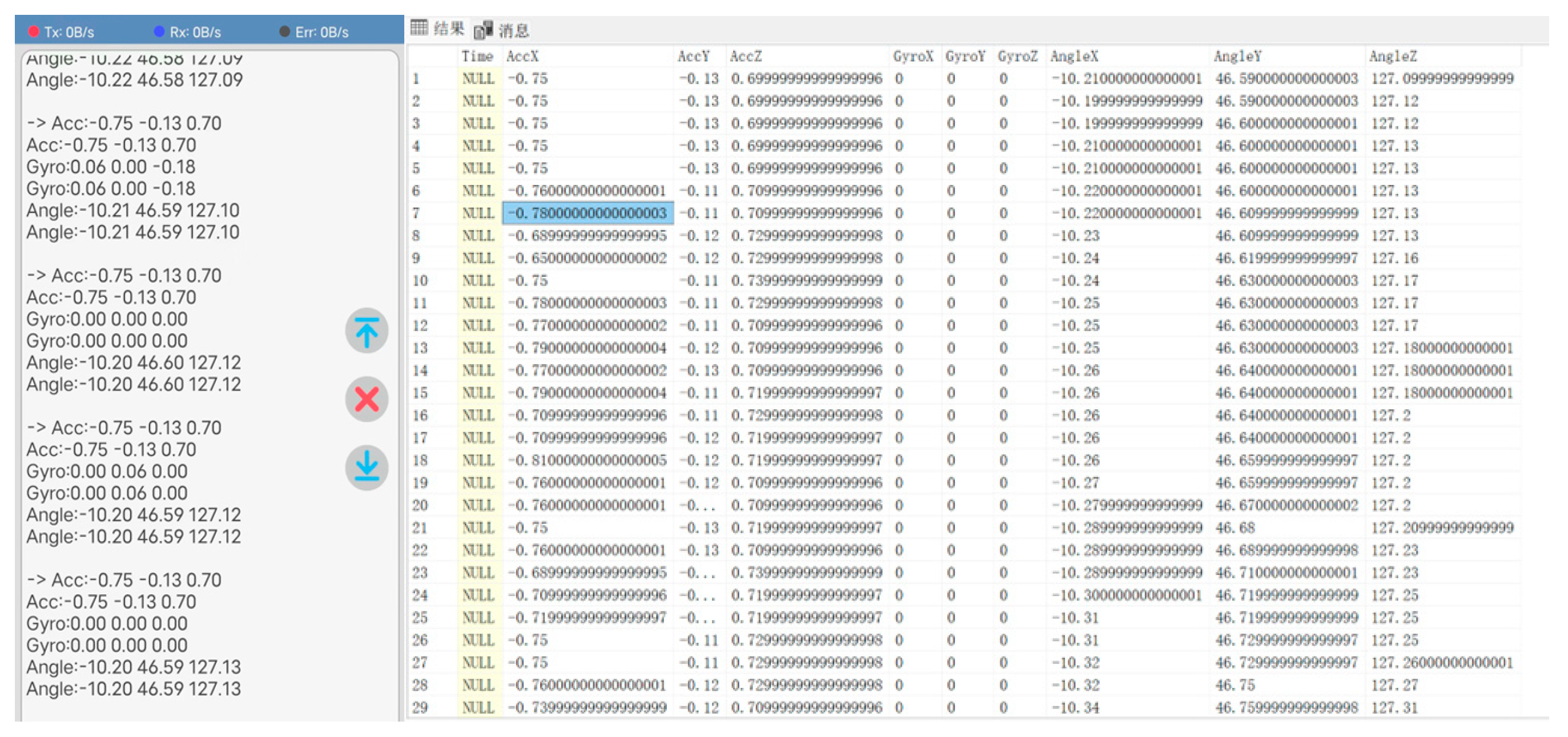
The collected JY901S sensor angle data and acceleration data are shown in
Figure 33 (left), and the sensor data obtained from the mobile end is stored in the corresponding SQL Server database table. The storage result is shown in
Figure 33 (right).
(2) Data transfer between MATLAB and database
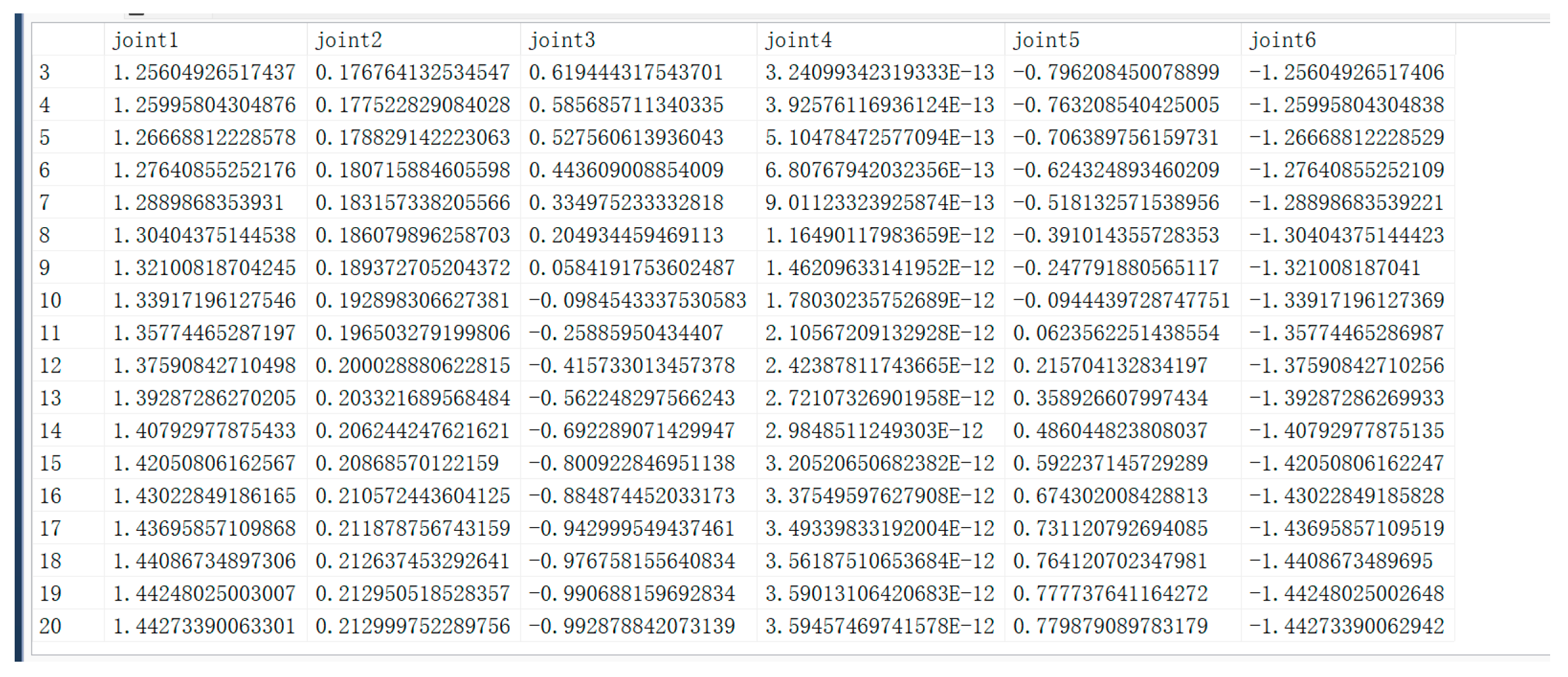
The configuration of the development environment between MATLAB and the database needs to be established before data transfer, i.e., establishing ODBC (Open Database Connectivity) communication. ODBC (Open Database Connectivity) is a standardized interface. Its main use is to establish communication between the database and the application program. Because it allows applications to access various databases using SQL statements, it is no longer necessary to write specific code programs for each database. ODBC simplifies the cumbersome process of database–application interaction by providing an interface layer under a unified standard. After completing the configuration of the development environment, we tested the data transfer function. The output of the algorithm is the path points after path planning, and these path points are written in the “JointAngle” table in the SQL Server database. Each time the algorithm recalculates the path points, the data in the database needs to be synchronized and updated to ensure that the latest path point information can be uploaded and replace the old data in time. This process not only requires an efficient data transfer mechanism but also must ensure the consistency and accuracy of the data, so as to provide a reliable basis for subsequent operations. The results of data transmission are shown in
Figure 34.
(3) Data transfer between Unity 3D and the database
Before realizing the data transfer between Unity 3D and the database, the environment of the software must be configured at both ends. Unity 3D realizes the data transfer between Unity 3D and the database with the help of Visual Studio programming software and the C# language. Unity 3D software needs to configure the I18N.CJK.dll, I18N.dll, I18N.West.dll, and System.Data.dll files of the project in the Plugins file. CJK.dll, I18N.dll, and I18N.West.dll are used by Unity 3D to handle text display, character encoding, sorting, etc. System.Data.dll ensures that Unity 3D accesses the call data. The Visual Studio side needs to be configured with System.IO.Ports and System.Data.SqlClient, as shown in
Figure 35. The System.IO.Ports assembly provides developers with the ability to manipulate serial ports, enabling them to transfer and control data with hardware devices through serial communication. The System.Data.SqlClient assembly is primarily used to interact with Microsoft SQL Server databases. SqlClient defines some functions to help users connect to SQL Server databases, as well as perform data queries, calls, and so on.
Next, the TCP/IP communication protocol is enabled in the SQL Server Database Configuration Manager to ensure that the database can communicate over the network.
After the configuration of the environment files required above is completed, a corresponding C# script is written to control the access and invocation of the SQL Server database information by Unity 3D. A small section of the path planned by the circular interpolation of the robotic arm was selected in this test phase, and the result of reading data is shown in
Figure 36a. The script controls the robotic arm to assign the read rotation angles of each joint to reproduce the trajectory of the robotic arm, and the result of the reproduced trajectory is shown in
Figure 36b.
(4) Unity 3D reading Excel table information
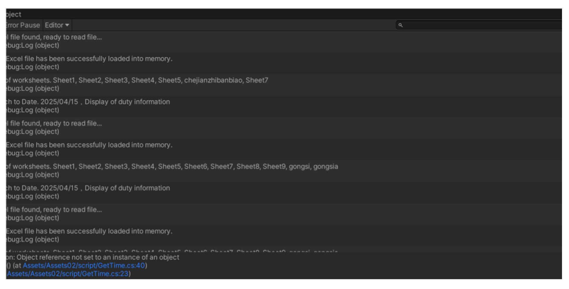
The library file in Unity 3D is configured, and the ExcelDataReader.dll and ExcelDataReader.DataSet.dll files are imported into the Plugins file. Then, a C# script is written to realize the reading of the corresponding table content. The process of reading data after successful connection is shown in
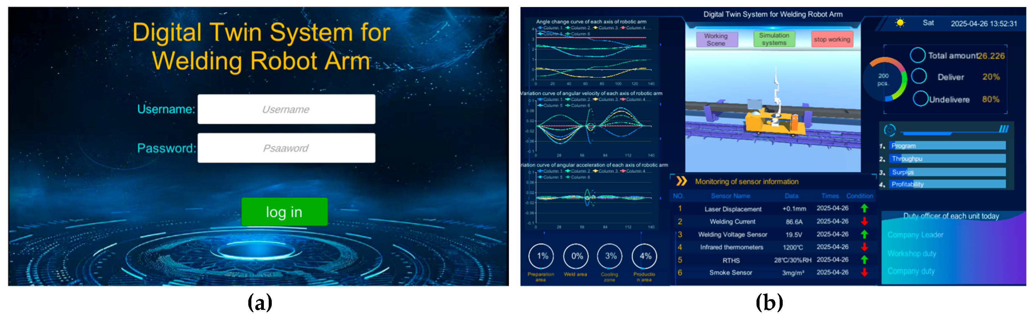
Figure 37. Data visualization will be described in detail in the UI section later in this chapter.
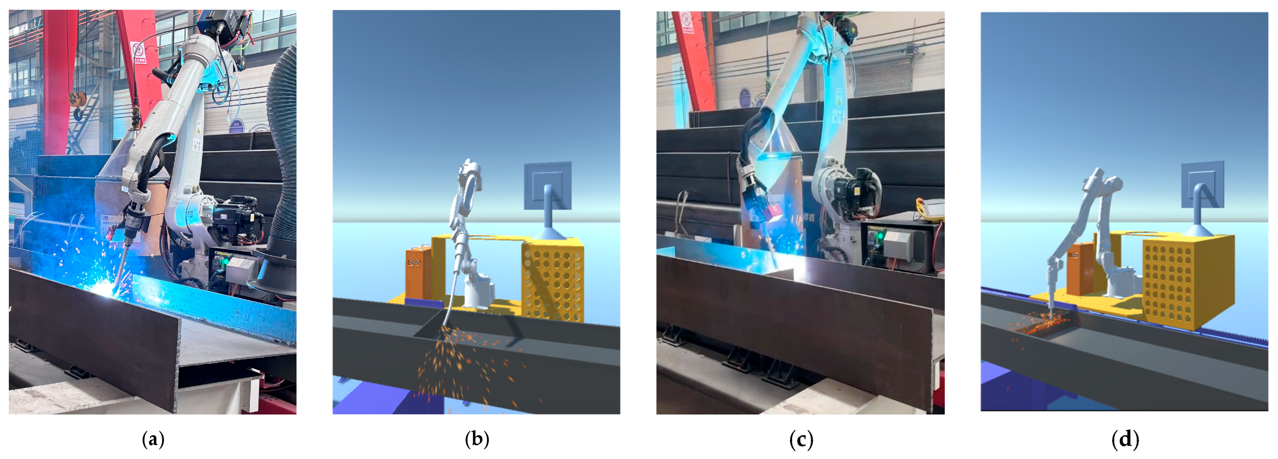
(5) Synchronized validation of Unity 3D side with physical side
In the previous section, the JY901S sensor was used to complete the data acquisition of the end-effector of the welding robot arm, and it was confirmed that the data can be properly transferred into the SQL Server database. It also completed the reading and writing of data between Unity 3D and the database. Now, an inverse kinematic function script is written in Unity 3D using C# to calculate the joint angle of the end-effector to reach the target position and attitude according to the position and attitude of the welding robot arm end-effector. Then, according to the calculation results, the welding robot arm joints are controlled to rotate to the specified angle to achieve synchronization with the physical end of the welding robot arm. The verification results are shown in
Figure 38.


 and
and 


