
Research on a Visually Assisted Efficient Blind-Guiding System and an Autonomous Shopping Guidance Robot Arm Adapted to the Complex Environment of Farmers’ Markets

 , , ,
, , ,  ,
,
Abstract
1. Introduction
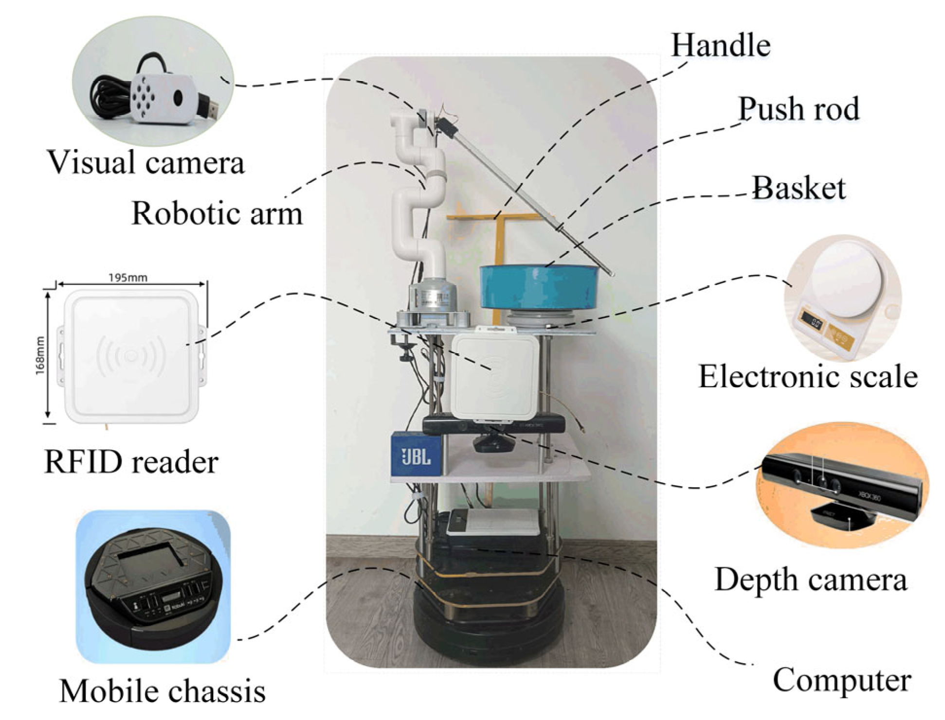
2. Experimental Equipment
3. High-Precision Mapping and Intelligent Navigation Strategy
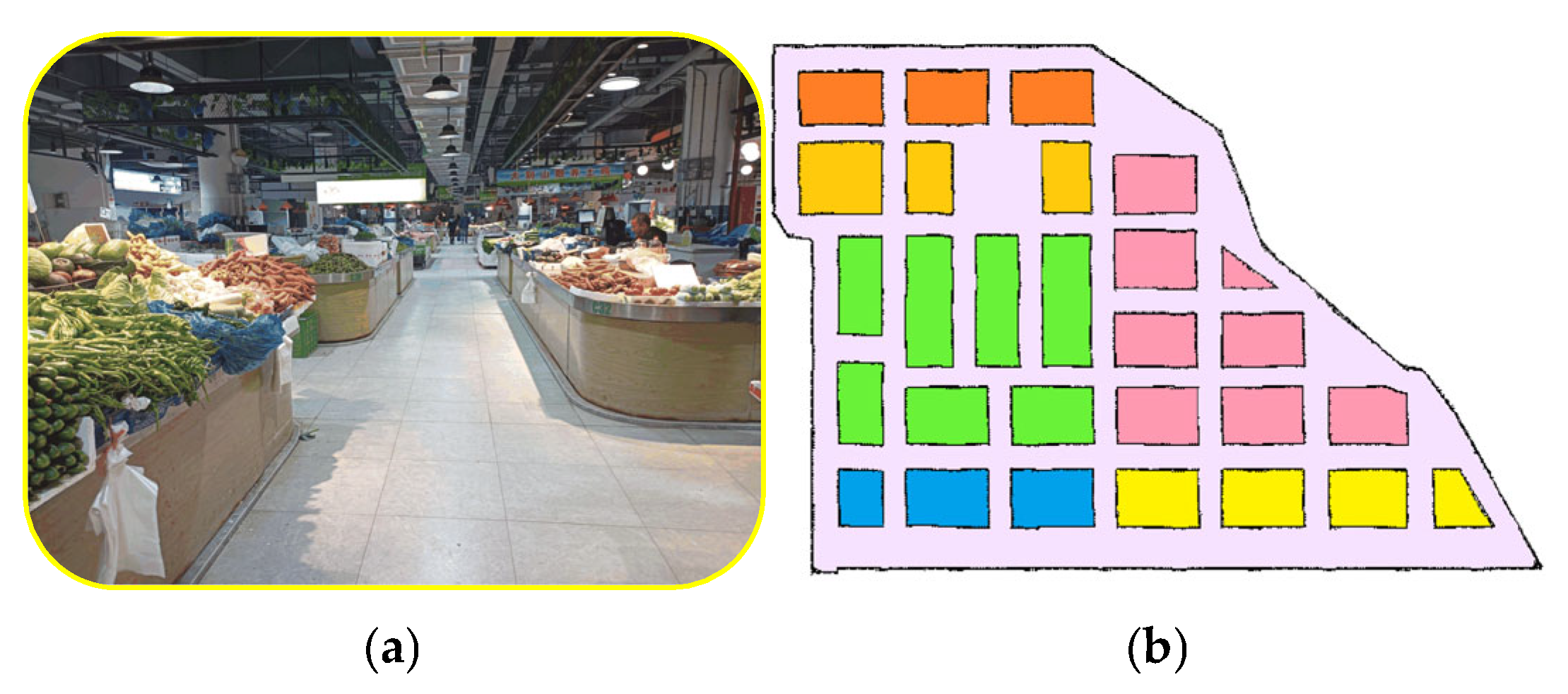
3.1. Synchronous High-Precision Mapping and Automatic Product Detection
3.1.1. Position Calibration Method Based on RFID Tags
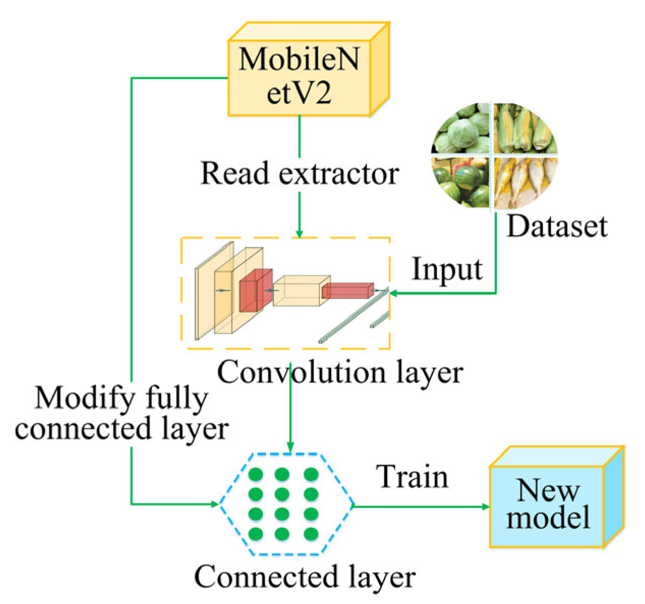
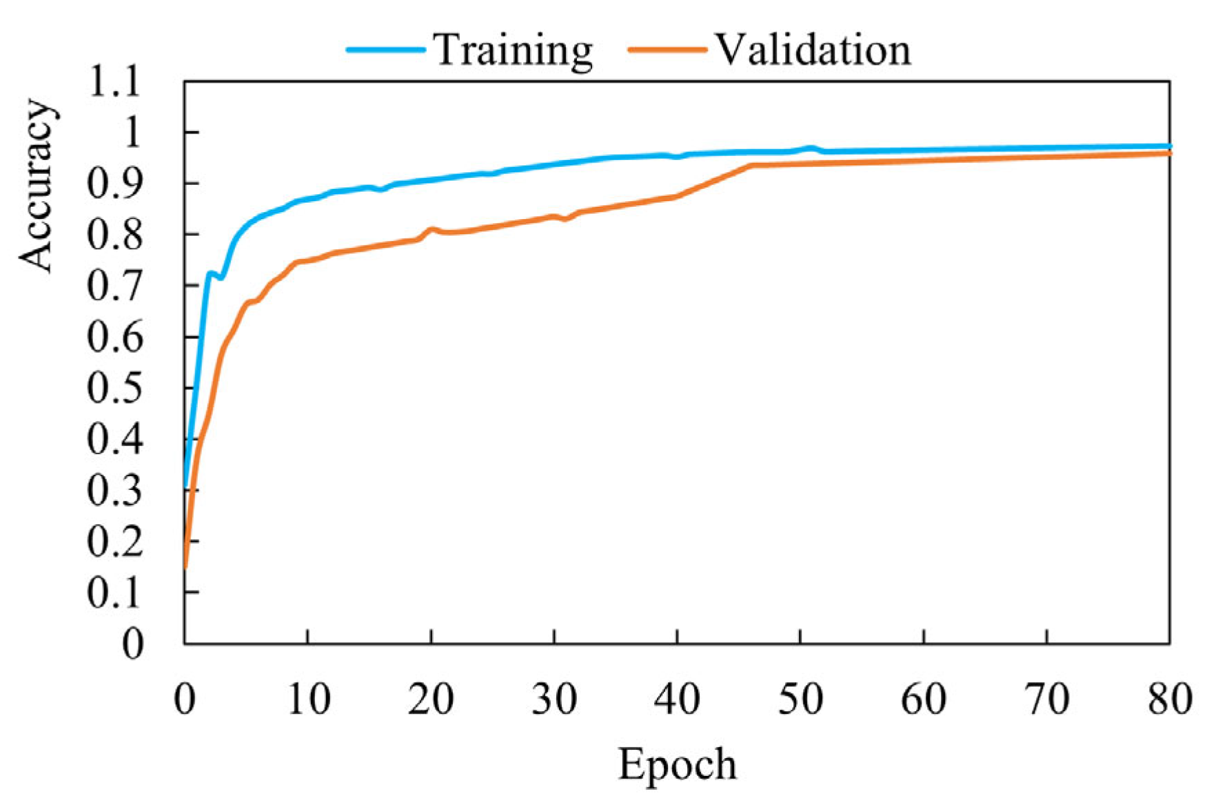
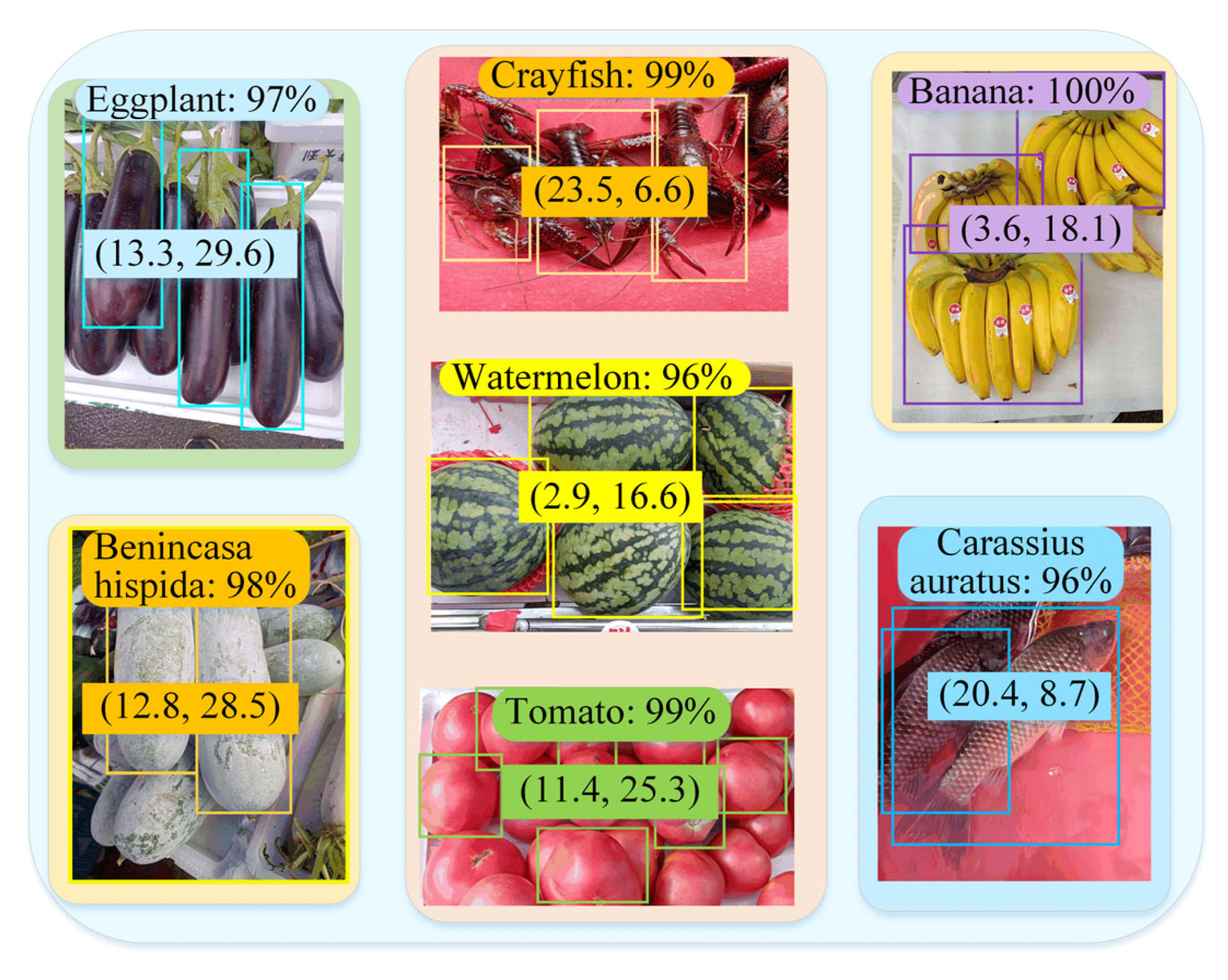
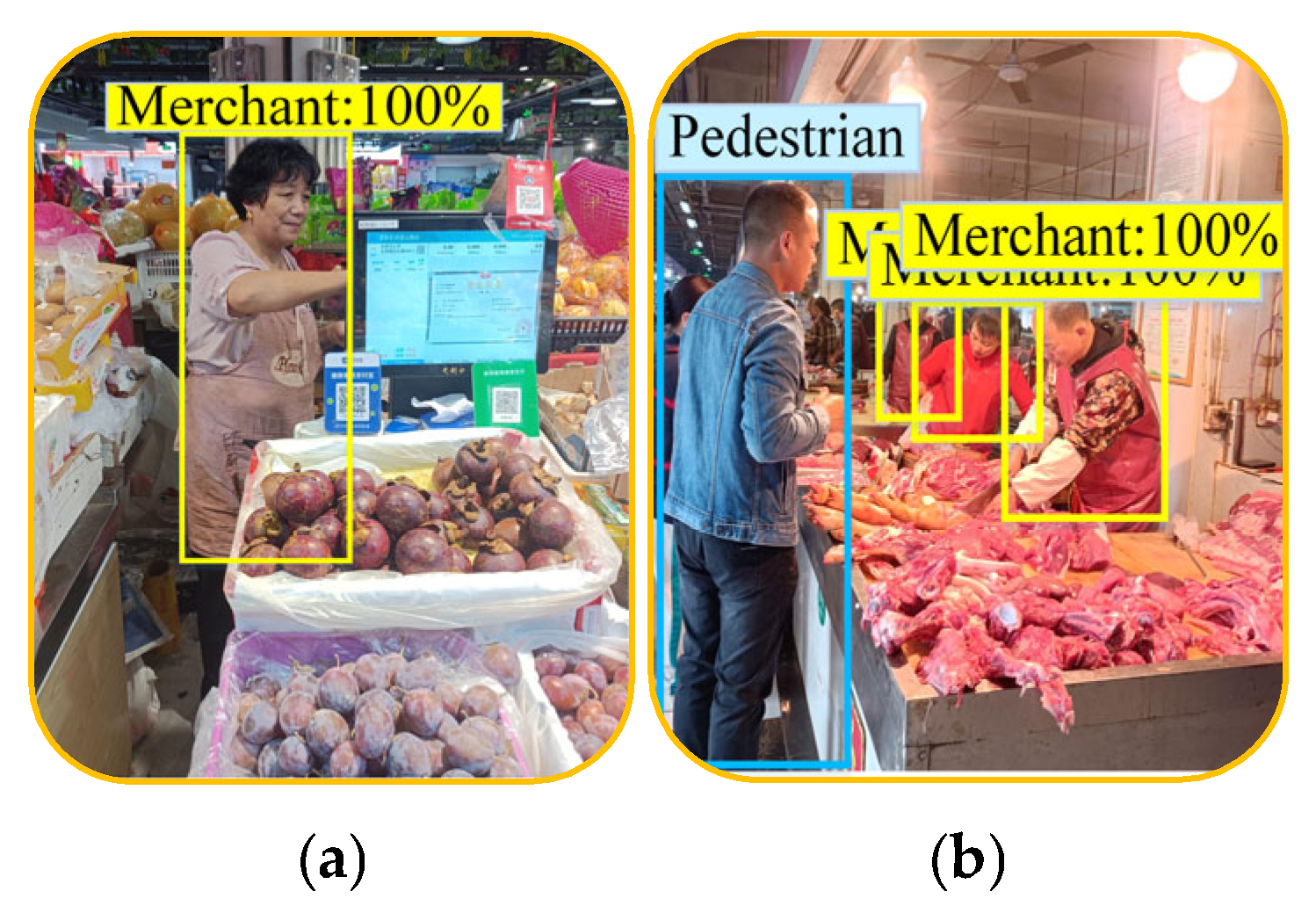
3.1.2. Detection of Product Information Based on Transfer Learning
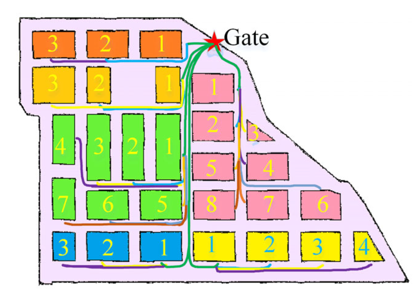
3.2. Fixed-Route Navigation Strategy Based on A*-FRN Method
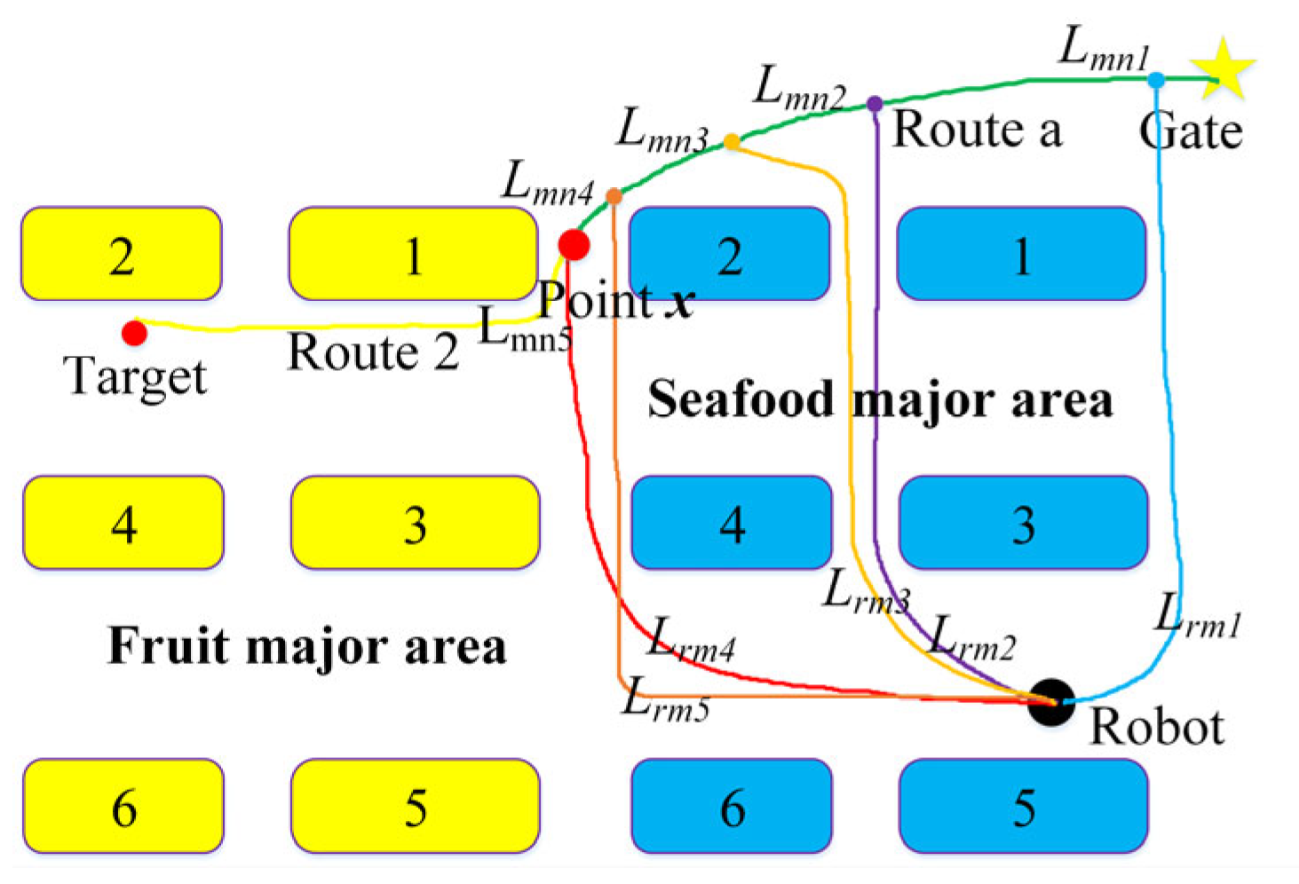
3.2.1. A*-FRN Algorithm
- 1.
- Calculate the route length Lrm from the robot to any point m on fixed route a with the A* method;
- 2.
- Then, calculate the route length Lmn from point m along route a and route 2 to target stall 2;
- 3.
- Add Lrm and Lmn to obtain the total length Lsmn = Lrm + Lmn;
- 4.
- Compare Lsmn with the smallest value. The corresponding point m is optimal point x.
3.2.2. A* Method
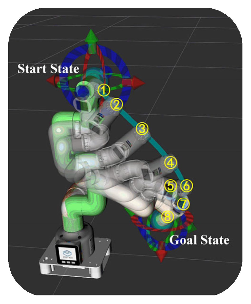
3.3. Intelligent Guidance and Autonomous Shopping Strategy Based on Robotic Arm
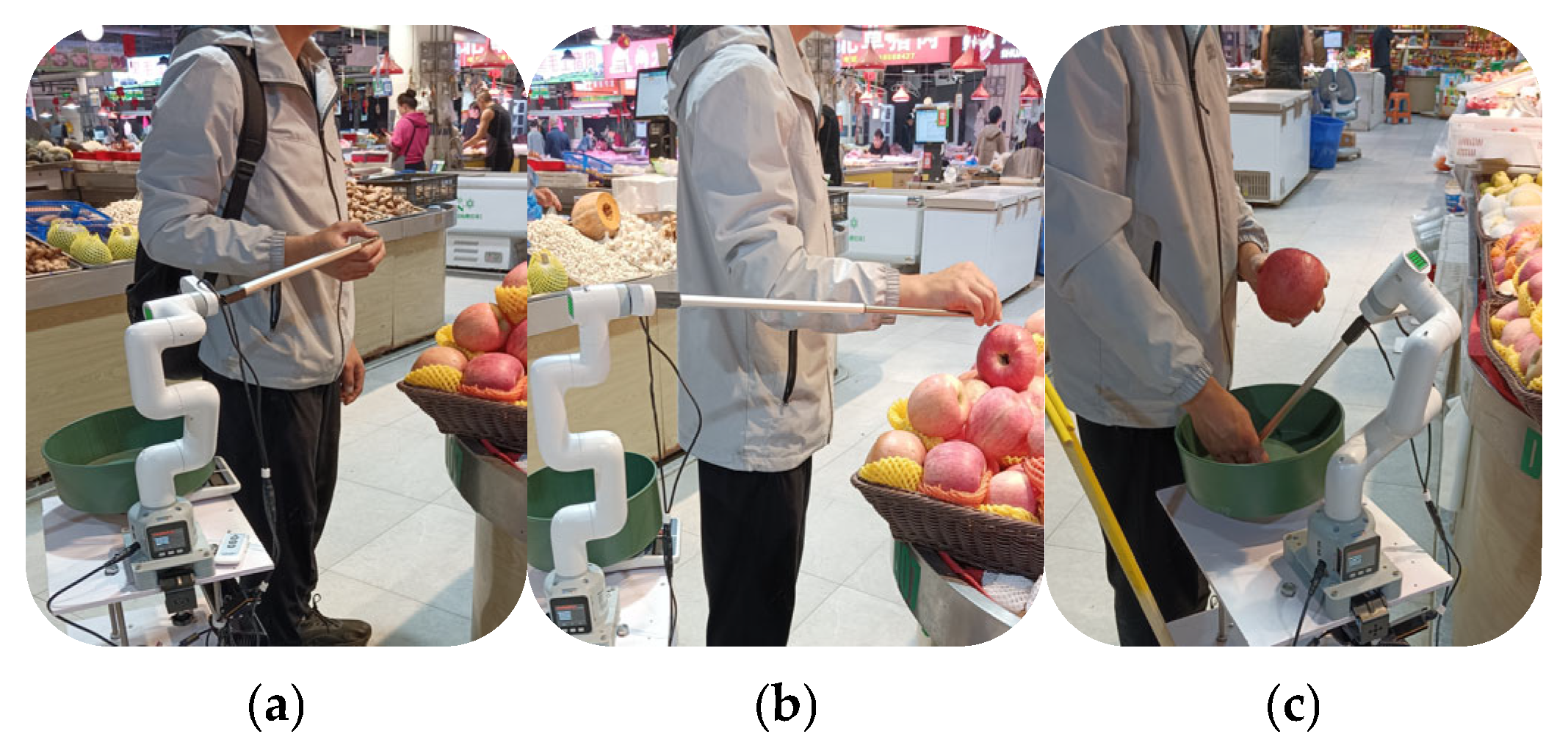
3.3.1. Intelligent Guidance for VI People to Select Fresh Products
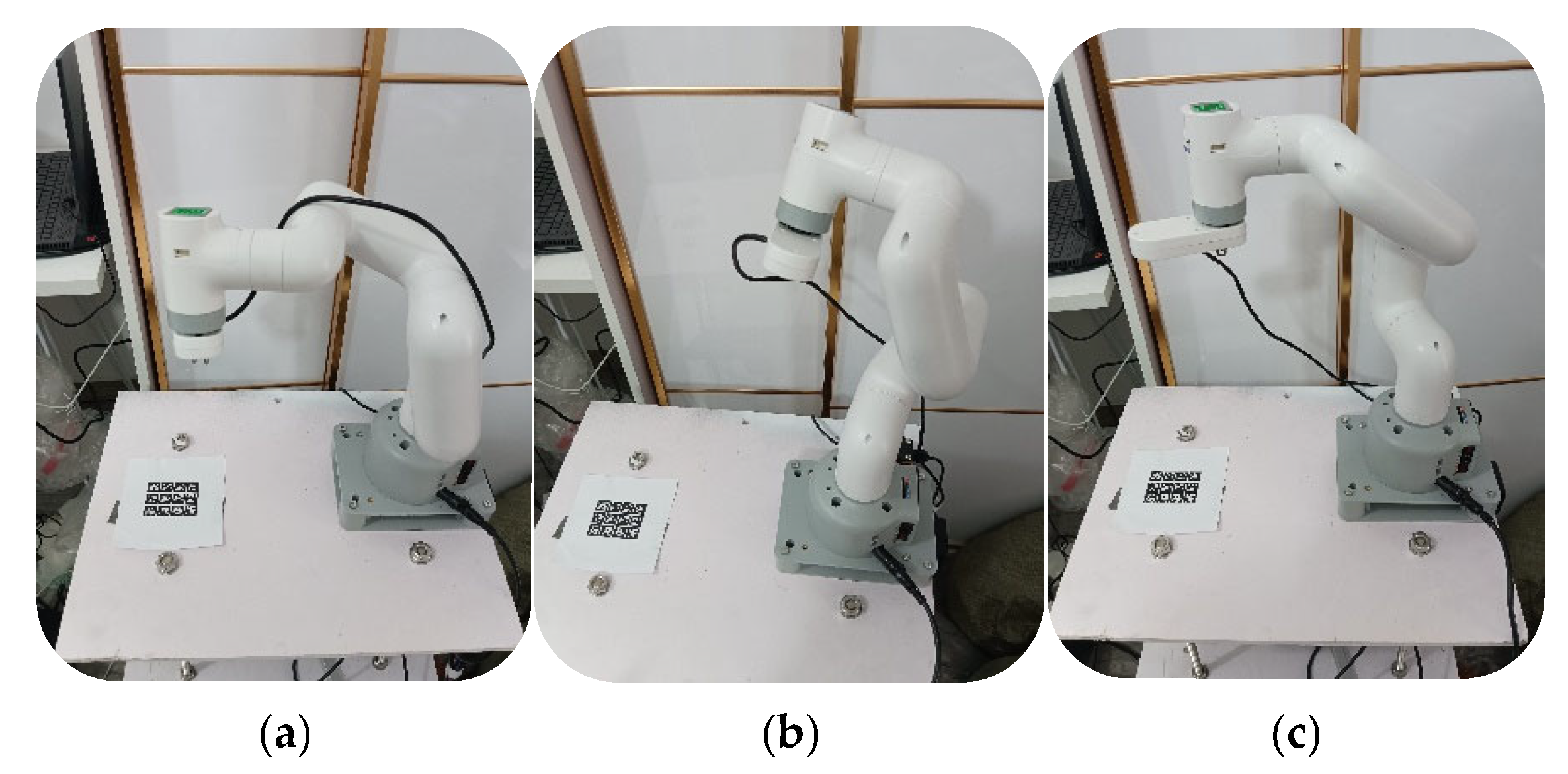
- (a)
- Control the motion of the robotic arm
- (b)
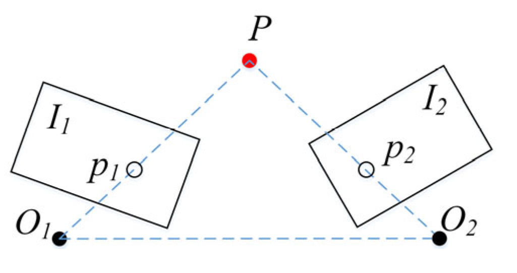
- Locating products and VI people’s fingers based on monocular visuals
- (c)
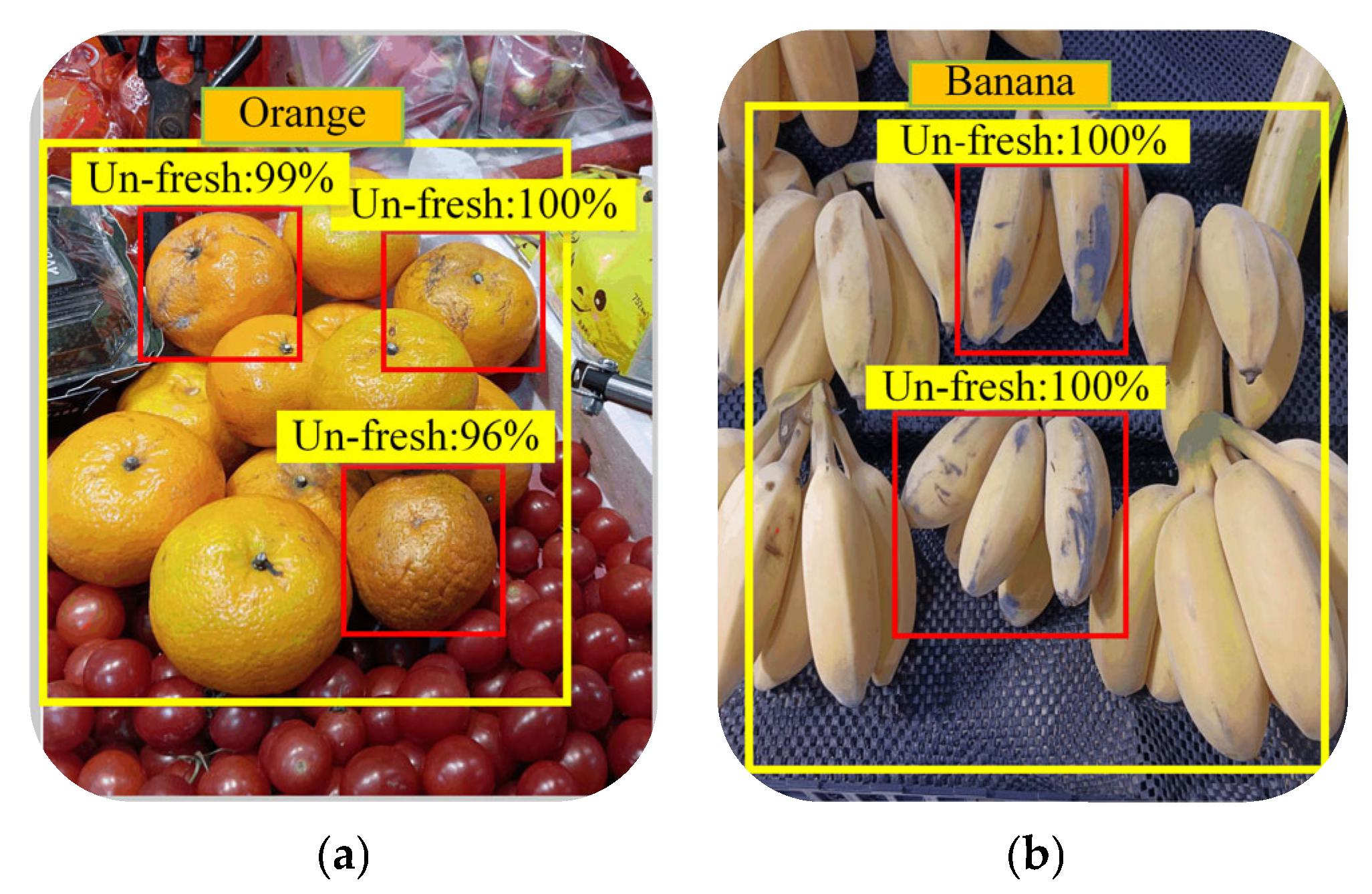
- Identify fresh products based on transfer learning
3.3.2. Robot Autonomous Shopping Strategy
4. Experiment and Discussion
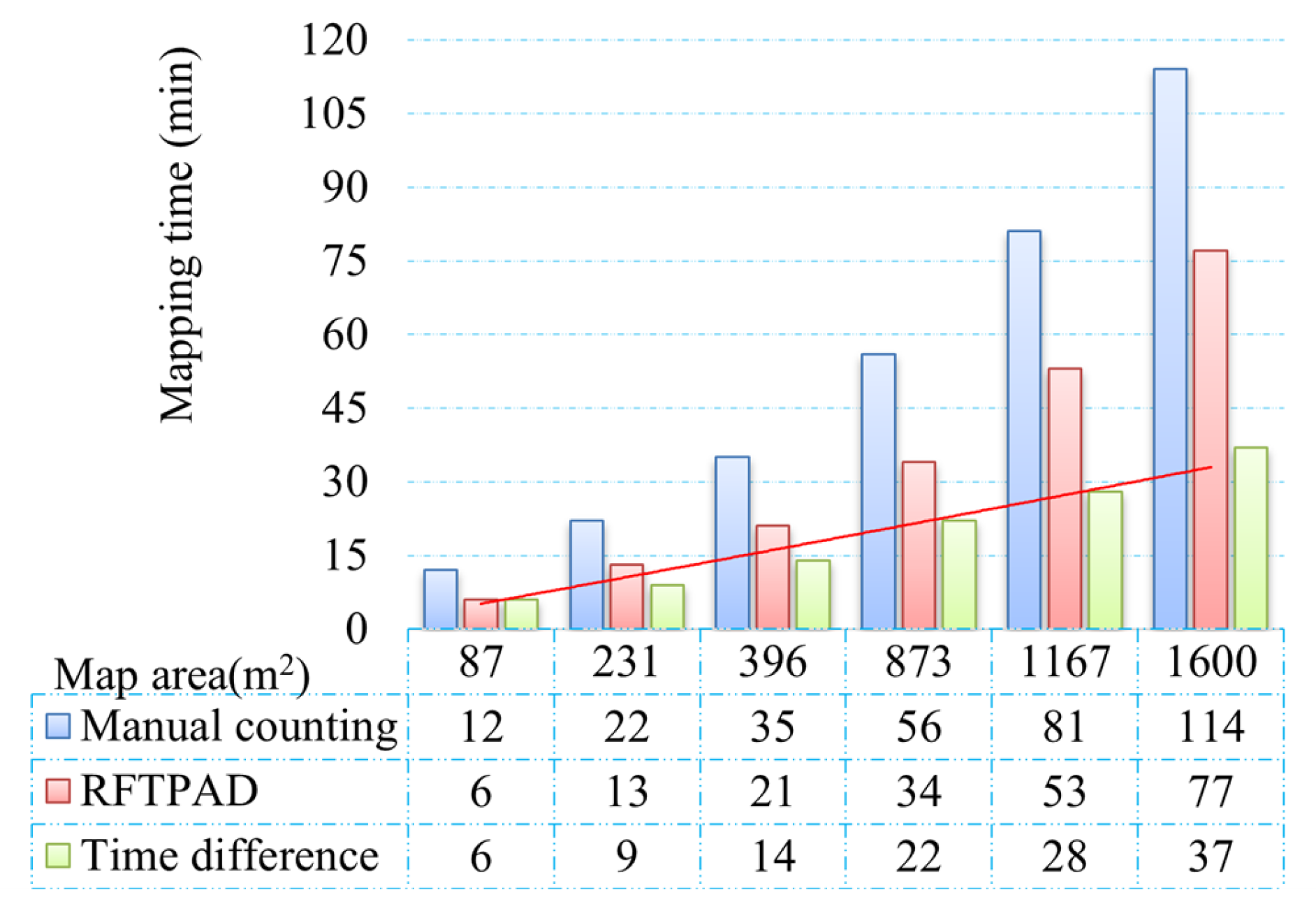
4.1. Comparative Analysis of Mapping Accuracy and Efficiency with RFTPAD
4.1.1. Accuracy Analysis Between RFTPAD and Cartographer Algorithm
4.1.2. Synchronize Detection of Product Information
4.2. Fixed-Route Navigation Trial with A*-FRN Algorithm
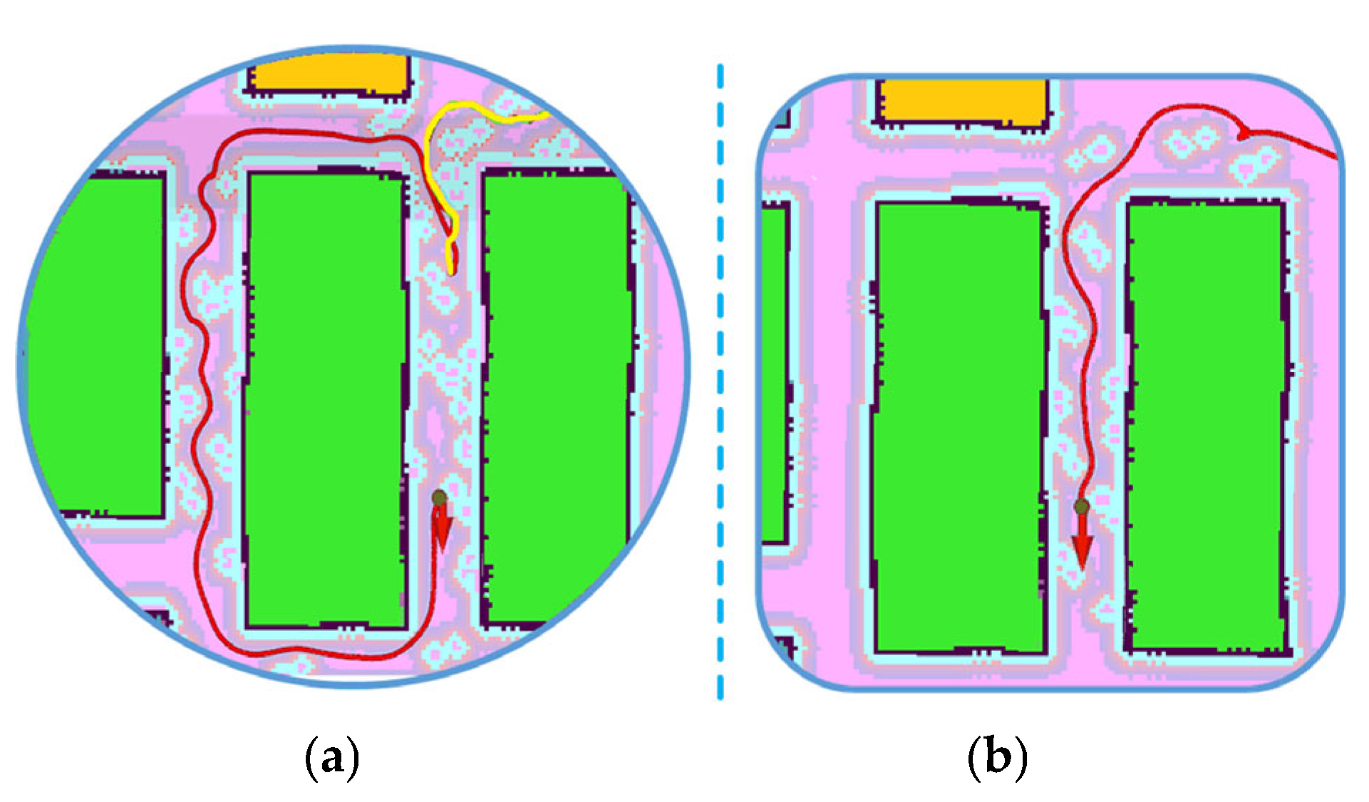
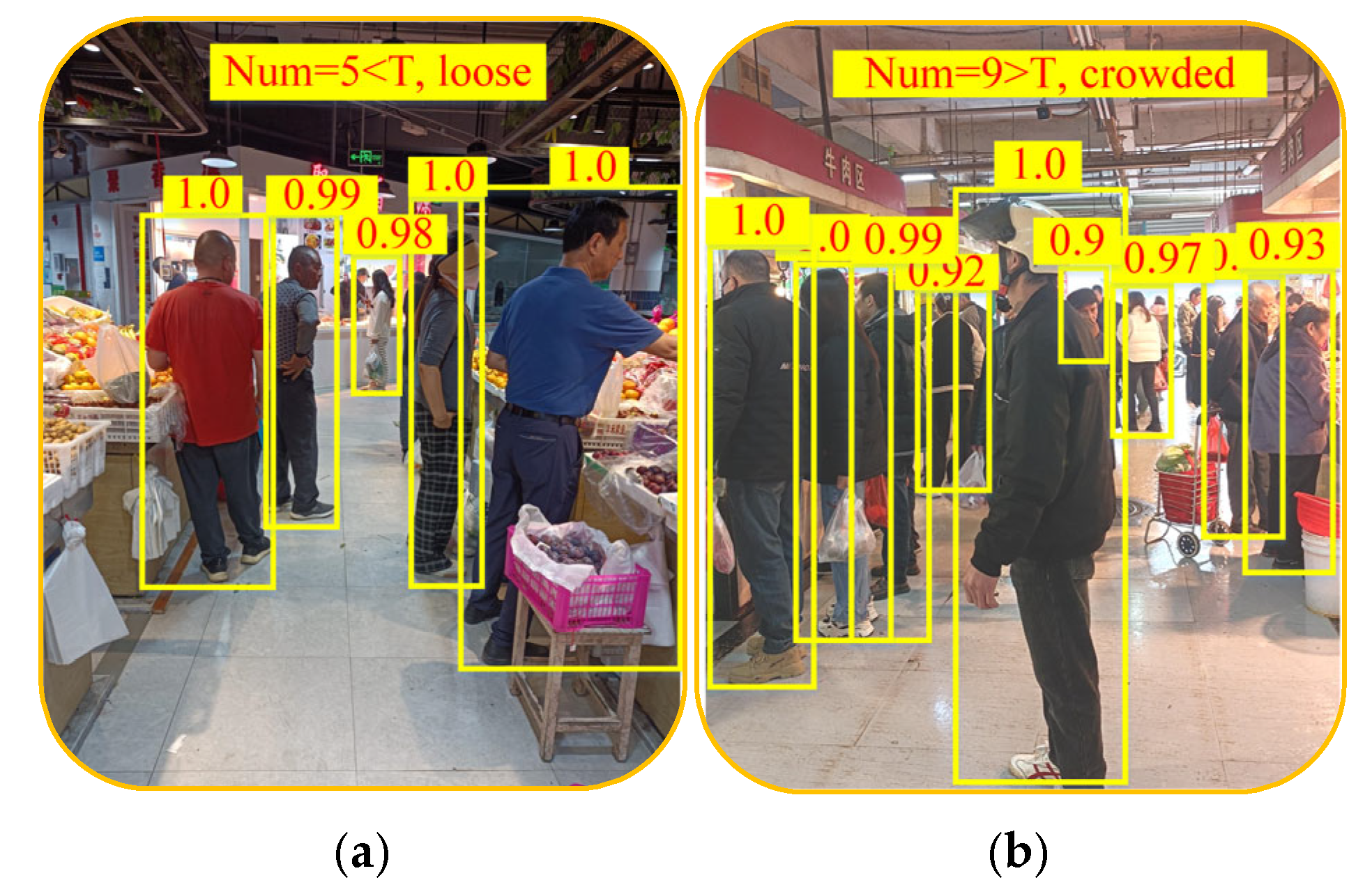
4.2.1. Analysis of Robot’s Detour Behavior When Aisle Is Crowded
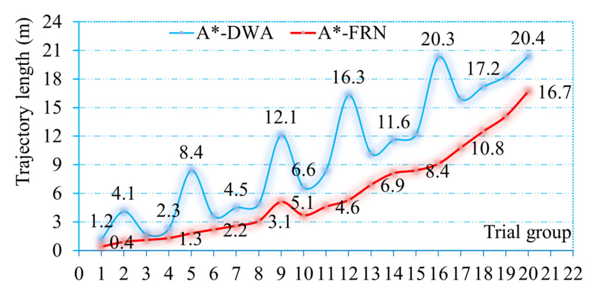
4.2.2. Analysis of Robot’s Driving Trajectory Length When Aisle Is Crowded
4.3. Intelligent Guided and Autonomous Shopping Based on Robotic Arm
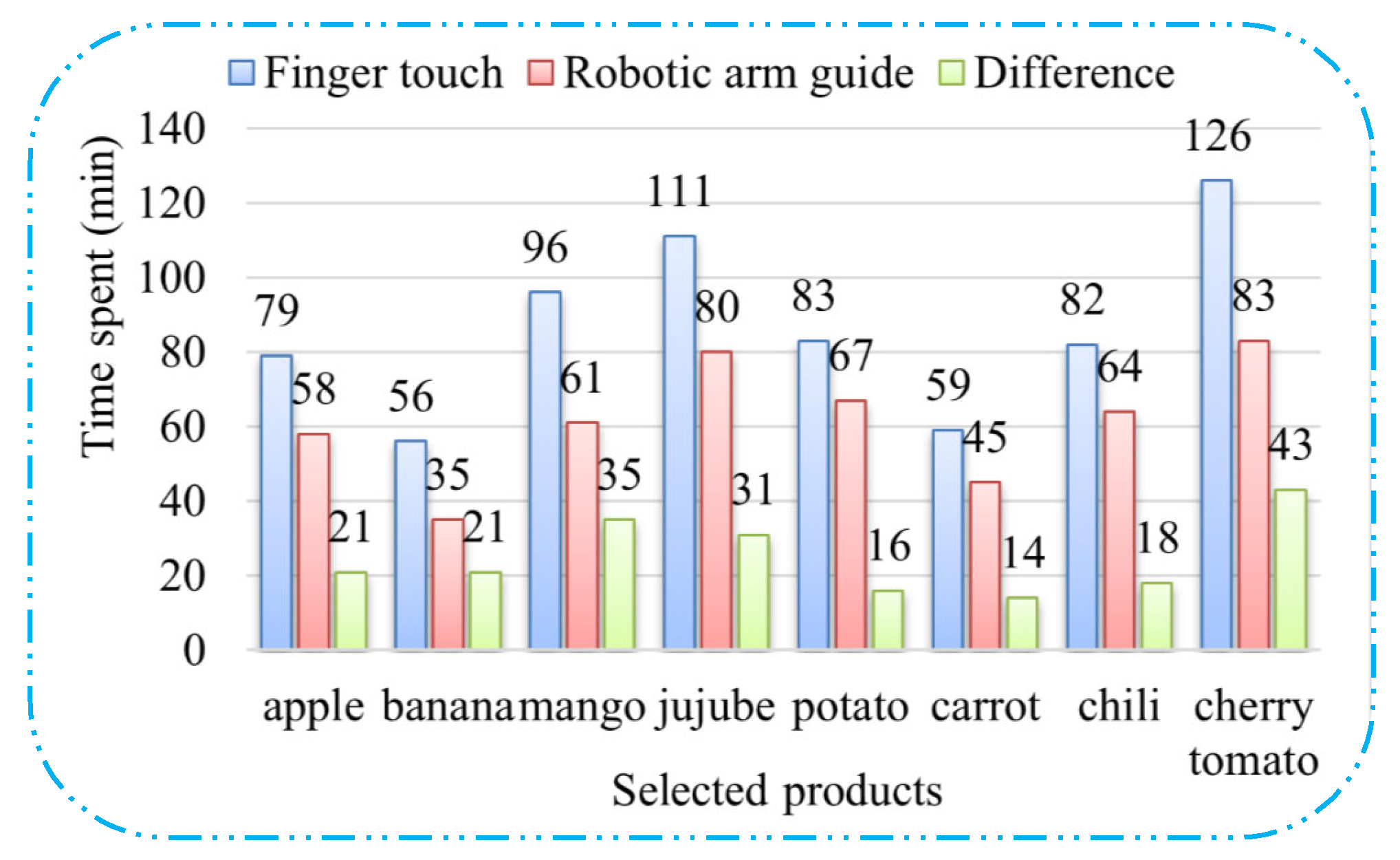
4.3.1. Intelligent Selection of Fresh Products with the Assistance of a Robotic Arm
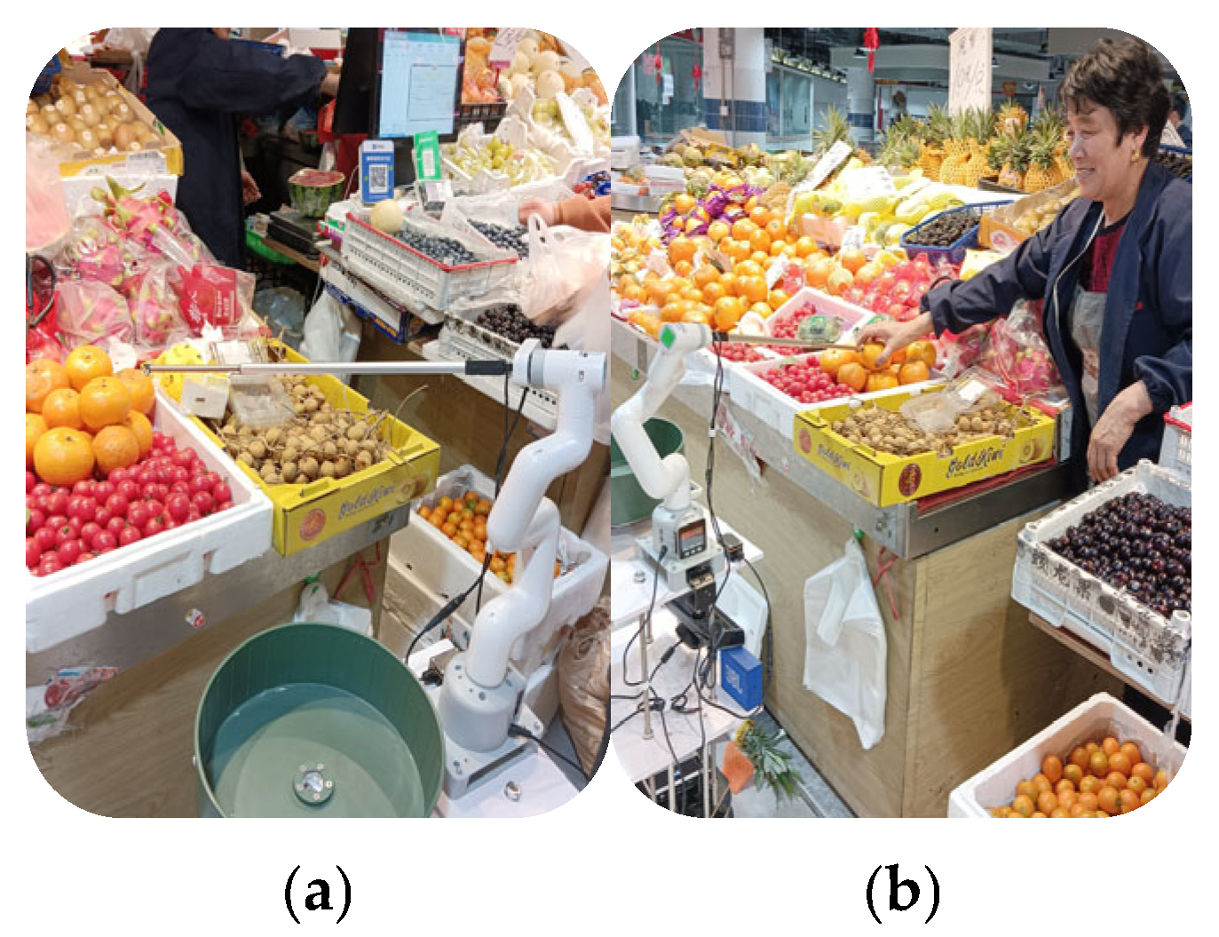
4.3.2. Autonomous Shopping Based on Robotic Arm
5. Conclusions
Author Contributions
Funding
Institutional Review Board Statement
Informed Consent Statement
Data Availability Statement
Acknowledgments
Conflicts of Interest
References
- Zou, W.; Hua, G.; Zhuang, Y.; Tian, S. Real-time passable area segmentation with consumer RGB-D cameras for the Visually Impaired. IEEE Trans. Instrum. Meas. 2023, 72, 2513011. [Google Scholar] [CrossRef]
- Plikynas, D.; Žvironas, A.; Gudauskis, M.; Budrionis, A.; Daniušis, P.; Sliesoraitytė, I. Research advances of indoor navigation for blind people: A brief review of technological instrumentation. IEEE Instrum. Meas. Mag. 2020, 23, 22–32. [Google Scholar] [CrossRef]
- Wang, J.; Liu, E.; Geng, Y.; Qu, X.; Wang, R. A survey of 17 indoor travel assistance systems for blind and visually impaired people. IEEE Trans. Hum.-Mach. Syst. 2022, 52, 134–148. [Google Scholar] [CrossRef]
- Berka, J.; Balata, J.; Mikovec, Z. Optimizing the number of bluetooth beacons with proximity approach at decision points for intermodal navigation of blind pedestrians. In Proceedings of the 2018 Federated Conference on Computer Science and Information Systems (FedCSIS), Poznan, Poland, 9–12 September 2018. [Google Scholar]
- Kunhoth, J.; Karkar, A.G.; Al-Maadeed, S.; Al-Attiyah, A. Comparative analysis of computer-vision and BLE technology based indoor navigation systems for people with visual impairments. Int. J. Health Geogr. 2019, 18, 29. [Google Scholar] [CrossRef]
- AL-Madani, B.; Orujov, F.; Maskeliūnas, R.; Damaševičius, R.; Venčkauskas, A. Fuzzy logic type-2 based wireless indoor localization system for navigation of visually impaired people in buildings. Sensors 2019, 19, 2114. [Google Scholar] [CrossRef]
- Ahmetovic, D.; Gleason, C.; Ruan, C.; Kitani, K.; Asakawa, C. NavCog: A navigational cognitive assistant for the blind. In Proceedings of the 18th International Conference on Human Computer Interaction with Mobile Devices and Services, New York, NY, USA, 6 September 2016. [Google Scholar]
- Ivanov, R. Indoor navigation system for visually impaired. In Proceedings of the 11th International Conference on Computer Systems and Technologies and Workshop for PhD Students in Computing on International Conference on Computer Systems and Technologies, Sofia, Bulgaria, 17–18 June 2010. [Google Scholar]
- Gomes, J.P.; Sousa, J.P.; Cunha, C.R.; Morais, E.P. An indoor navigation architecture using variable data sources for blind and visually impaired persons. In Proceedings of the 2018 13th Iberian Conference on Information Systems and Technologies (CISTI), Caceres, Spain, 13–16 June 2018. [Google Scholar]
- Zhang, J.; Yang, X.; Wang, W.; Guan, J.; Ding, L.; Lee, V. Automated guided vehicles and autonomous mobile robots for recognition and tracking in civil engineering. Autom. Constr. 2023, 146, 104699. [Google Scholar] [CrossRef]
- Škrabánek, P.; Vodička, P. Magnetic strips as landmarks for mobile robot navigation. In Proceedings of the 2016 International Conference on Applied Electronics (AE), Pilsen, Czech Republic, 6–7 September 2016. [Google Scholar]
- Cruz, J.D.; Domingo, C.B.; Garcia, R.G. Automated service robot for catering businesses using arduino mega 2560. In Proceedings of the 2023 15th International Conference on Computer and Automation Engineering (ICCAE), Sydney, Australia, 3–5 March 2023. [Google Scholar]
- Pauly, L.; Baiju, M.V.; Viswanathan, P.; Jose, P.; Paul, D.; Sankar, D. CAMbot: Customer assistance mobile manipulator robot. In Proceedings of the 2015 IEEE Bombay Section Symposium (IBSS), Mumbai, India, 10–11 September 2015. [Google Scholar]
- Nechyporenko, N.; Morales, A.; Cervera, E.; Pobil, A.P.D. A practical approach for picking items in an online shopping warehouse. Appl. Sci. 2021, 11, 5805. [Google Scholar] [CrossRef]
- Liu, J. Application of RFID technology in SLAM. South-Cent. Univ. Natl. 2008, 27, 84–87. [Google Scholar]
- DiGiampaolo, E.; Martinelli, F.; Romanelli, F. Exploiting the Orientation of Trilateration UHF RFID Tags in Robot Localization and Mapping. In Proceedings of the 2022 IEEE 12th International Conference on RFID Technology and Applications (RFID-TA), Cagliari, Italy, 12–14 September 2022. [Google Scholar]
- Kroumov, V.; Okuyama, K. Localisation and Position Correction for Mobile Robot using Artificial Visual Landmarks. Int. J. Adv. Mechatron. Syst. 2012, 4, 212–217. [Google Scholar] [CrossRef]
- Dwijotomo, A.; Rahman, M.A.A.; Ariff, M.H.M.; Zamzuri, H.; Azree, W.M.H.W. Cartographer SLAM method for optimization with an adaptive multi-distance scan scheduler. Appl. Sci. 2020, 10, 347. [Google Scholar] [CrossRef]
- Gao, Q.; Jia, H.; Liu, Y.; Tian, X. Design of mobile robot based on cartographer slam algorithm. In Proceedings of the 2019 2nd International Conference on Informatic, Hangzhou, China, 6 May 2019. [Google Scholar]
- Zhang, F.; Zheng, S.; He, Y.; Shao, X. The research on attitude correction method of robot monocular vision positioning system. In Proceedings of the 2016 IEEE International Conference on Robotics and Biomimetics (ROBIO), Qingdao, China, 3–7 December 2016. [Google Scholar]
- Venkateswara, H.; Chakraborty, S.; Panchanathan, S. Deep learning system for domain adaptation in computer vision: Learning transferable feature representations. IEEE Signal Process. Mag. 2017, 34, 117–129. [Google Scholar] [CrossRef]
- Sandler, M.; Howard, A.; Zhu, M.; Zhmoginov, A.; Chen, L.C. MobileNetV2: Inverted Residuals and Linear Bottlenecks. In Proceedings of the 2018 IEEE/CVF Conference on Computer Vision and Pattern Recognition, Salt Lake City, UT, USA, 18–23 June 2018. [Google Scholar]
- Gul, F.; Rahiman, W.; Alhady, S.S.N. A comprehensive study for robot navigation techniques. Cogent Eng. 2019, 6, 1632046. [Google Scholar] [CrossRef]
- Peng, J.; Huang, Y.; Luo, G. Robot path planning based on improved A* algorithm. Cybern. Inf. Technol. 2015, 15, 171–180. [Google Scholar] [CrossRef]
- Ayawli, B.B.K.; Chellali, R.; Appiah, A.Y.; Kyeremeh, F. An overview of nature-inspired, conventional, and hybrid methods of autonomous vehicle path planning. J. Adv. Transp. 2018, 2018, 8269698. [Google Scholar] [CrossRef]
- Canadas-Aranega, F.; Moreno, J.C.; Blanco-Claraco, J.L. A PID-based control architecture for mobile robot path planning in greenhouses. IFAC Pap. 2024, 58, 503–508. [Google Scholar] [CrossRef]
- Lin, J.; Zheng, R.; Zhang, Y.; Feng, J.; Li, W.; Luo, K. CFHBA-PID algorithm: Dual-loop PID balancing robot attitude control algorithm based on complementary factor and honey badger algorithm. Sensors 2022, 22, 4492. [Google Scholar] [CrossRef] [PubMed]
- Molinos, E.J.; Llamazares, A.; Ocaña, M. Dynamic window based approaches for avoiding obstacles in moving. Robot. Auton. Syst. 2019, 118, 112–130. [Google Scholar] [CrossRef]
- Guruji, A.K.; Agarwal, H.; Parsediya, D.K. Time-efficient A* algorithm for robot path planning. Procedia Technol. 2016, 23, 144–149. [Google Scholar] [CrossRef]
- Prabhu, S.G.R.; Kyberd, P.; Wetherall, J. Investigating an A-star Algorithm-based Fitness Function for Mobile Robot Evolution. In Proceedings of the 2018 22nd International Conference on System Theory, Control and Computing (ICSTCC), Sinaia, Romania, 10–12 October 2018. [Google Scholar]
- Singh, A.; Singla, A.; Soni, S. Extension of DH parameter method to hybrid manipulators used in robot-assisted surgery. Proc. Inst. Mech. Eng. Part H J. Eng. Med. 2015, 229, 703–712. [Google Scholar] [CrossRef]
- Mohammed, A.; Abdul Ameer, H.R.; Abdul-Zahra, D.S. Design of a Linear Mathematical Model to Control the Manipulator of a Robotic Arm with a Hexagonal Degree of Freedom. In Proceedings of the 2022 3rd Information Technology to Enhance e-Learning and Other Application (IT-ELA), Baghdad, Iraq, 27–28 December 2022. [Google Scholar]
- Khan, A.; Xiangming, C.; Xingxing, Z.; Quan, W.L. Closed form inverse kinematics solution for 6-DOF underwater manipulator. In Proceedings of the 2015 International Conference on Fluid Power and Mechatronics (FPM), Harbin, China, 5–7 August 2015. [Google Scholar]
- Huang, Y.; Jin, C. Path Planning Based on Improved RRT Algorithm. In Proceedings of the 2023 2nd International Symposium on Control Engineering and Robotics (ISCER), Hangzhou, China, 17–19 February 2023. [Google Scholar]
- Konyashov, V.V.; Sergeev, A.S.; Kolganov, O.A.; Fedorov, A.V.; Konyashova, K.A.; Bychenok, V.V. Study of the Applicability of the Method of Optical Triangulation for Evaluation of the Geometric Parameters and Cleanliness of the Surface of Products of Complex Shapes. In Proceedings of the 2023 7th International Conference on Information, Control, and Communication Technologies (ICCT), Astrakhan, Russian Federation, 2–6 October 2023. [Google Scholar]
- Fang, S.; Huang, X.; Chen, H.; Xi, N. Dual-arm robot assembly system for 3C product based on vision guidance. In Proceedings of the 2016 IEEE International Conference on Robotics and Biomimetics (ROBIO), Qingdao, China, 3–7 December 2016. [Google Scholar]
- Min, F.; Wang, Y.; Zhu, S. People counting based on multi-scale region adaptive segmentation and depth neural network. In Proceedings of the 2020 3rd International Conference on Artificial Intelligence and Pattern Recognition, Xiamen, China, 26–28 June 2020. [Google Scholar]
- Zhang, Z. A flexible new technique for camera calibration. IEEE Trans. Pattern Anal. Mach. Intell. 2000, 22, 1330–1334. [Google Scholar] [CrossRef]
- Yuan, F.; Xia, Z.; Tang, B.; Yin, Z.; Shao, X.; He, X. Calibration accuracy evaluation method for multi-camera measurement systems. Measurement 2025, 242, 116311. [Google Scholar] [CrossRef]


| Equipment Name | Model Number | Manufacturer | City and Country |
|---|---|---|---|
| Mobile chassis | Kobuki | Yujin Robot Co., Ltd. | Seoul, Republic of Korea |
| Depth camera | Kinect V1 | Microsoft Corporation | Redmond, WA, USA |
| Computer | MN50 | EVOC Intelligent Co., Ltd. | Shenzhen, China |
| RFID reader | NRD909 | WYUA Co., Ltd. | Guangzhou, China |
| Robotic arm | mycobot_280_M5 | Elephant Robotics Co., Ltd. | Shenzhen, China |
| Visual camera | cameraHolder_J6 | Elephant Robotics Co., Ltd. | Shenzhen, China |
| Electric push rod | MNTL | LONGXIANG Co., Ltd. | Changzhou, China |
| Input | Operator | t | c | n | s |
|---|---|---|---|---|---|
| 2242 × 3 | conv2d | - | 32 | 1 | 2 |
| 1122 × 32 | bottleneck | 1 | 16 | 1 | 1 |
| 1122 × 16 | bottleneck | 6 | 24 | 2 | 2 |
| 562 × 24 | bottleneck | 6 | 32 | 3 | 2 |
| 282 × 32 | bottleneck | 6 | 64 | 4 | 2 |
| 142 × 64 | bottleneck | 6 | 96 | 3 | 1 |
| 142 × 96 | bottleneck | 6 | 160 | 3 | 2 |
| 72 × 160 | bottleneck | 6 | 320 | 1 | 1 |
| 72 × 320 | conv2d 1 × 1 | - | 1280 | 1 | 1 |
| 72 × 1280 | avgpool 7 × 7 | - | - | 1 | - |
| 1 × 1 × 1280 | conv2d 1 × 1 | - | k | - |
| Joint i | Joint Angle θi (°) | Link Offset di (mm) | Link Length ai (mm) | Link Twist αi (°) |
|---|---|---|---|---|
| 1 | θ1 | 131.56 | 0 | 90 |
| 2 | θ2 | 0 | −110.4 | 0 |
| 3 | θ3 | 0 | −96 | 0 |
| 4 | θ4 | 64.62 | 0 | 90 |
| 5 | θ5 | 73.18 | 0 | −90 |
| 6 | θ6 | 48.6 | 0 | 0 |
| Group | Sm (m) | SnC (m) | SnR (m) | σ1C (m) | σ1R (m) |
|---|---|---|---|---|---|
| 1 | 15.121 | 15.152 | 15.097 | 0.031 | 0.024 |
| 2 | 22.353 | 22.396 | 22.389 | 0.043 | 0.036 |
| 3 | 29.468 | 29.419 | 29.429 | 0.049 | 0.039 |
| 4 | 34.644 | 34.583 | 34.597 | 0.061 | 0.047 |
| 5 | 38.517 | 38.595 | 38.456 | 0.078 | 0.061 |
| 6 | 41.376 | 41.460 | 41.439 | 0.084 | 0.063 |
| 7 | 46.243 | 46.154 | 46.178 | 0.089 | 0.065 |
| 8 | 55.689 | 55.587 | 55.723 | 0.102 | 0.074 |
Disclaimer/Publisher’s Note: The statements, opinions and data contained in all publications are solely those of the individual author(s) and contributor(s) and not of MDPI and/or the editor(s). MDPI and/or the editor(s) disclaim responsibility for any injury to people or property resulting from any ideas, methods, instructions or products referred to in the content. |
© 2025 by the authors. Licensee MDPI, Basel, Switzerland. This article is an open access article distributed under the terms and conditions of the Creative Commons Attribution (CC BY) license (https://creativecommons.org/licenses/by/4.0/).
Share and Cite
Liu, M.; Chen, Y.; Rao, J.; Giernacki, W.; Wang, Z.; Chen, J. Research on a Visually Assisted Efficient Blind-Guiding System and an Autonomous Shopping Guidance Robot Arm Adapted to the Complex Environment of Farmers’ Markets. Sensors 2025, 25, 3785. https://doi.org/10.3390/s25123785
Liu M, Chen Y, Rao J, Giernacki W, Wang Z, Chen J. Research on a Visually Assisted Efficient Blind-Guiding System and an Autonomous Shopping Guidance Robot Arm Adapted to the Complex Environment of Farmers’ Markets. Sensors. 2025; 25(12):3785. https://doi.org/10.3390/s25123785
Chicago/Turabian StyleLiu, Mei, Yunhua Chen, Jinjun Rao, Wojciech Giernacki, Zhiming Wang, and Jinbo Chen. 2025. "Research on a Visually Assisted Efficient Blind-Guiding System and an Autonomous Shopping Guidance Robot Arm Adapted to the Complex Environment of Farmers’ Markets" Sensors 25, no. 12: 3785. https://doi.org/10.3390/s25123785
APA StyleLiu, M., Chen, Y., Rao, J., Giernacki, W., Wang, Z., & Chen, J. (2025). Research on a Visually Assisted Efficient Blind-Guiding System and an Autonomous Shopping Guidance Robot Arm Adapted to the Complex Environment of Farmers’ Markets. Sensors, 25(12), 3785. https://doi.org/10.3390/s25123785