A Dual-Band Flexible MIMO Array Antenna for Sub-6 GHz 5G Communications

 ,
,  ,
,  , ,
, ,  ,
,  , ,
, ,
Abstract
1. Introduction
2. Single-Element Antenna
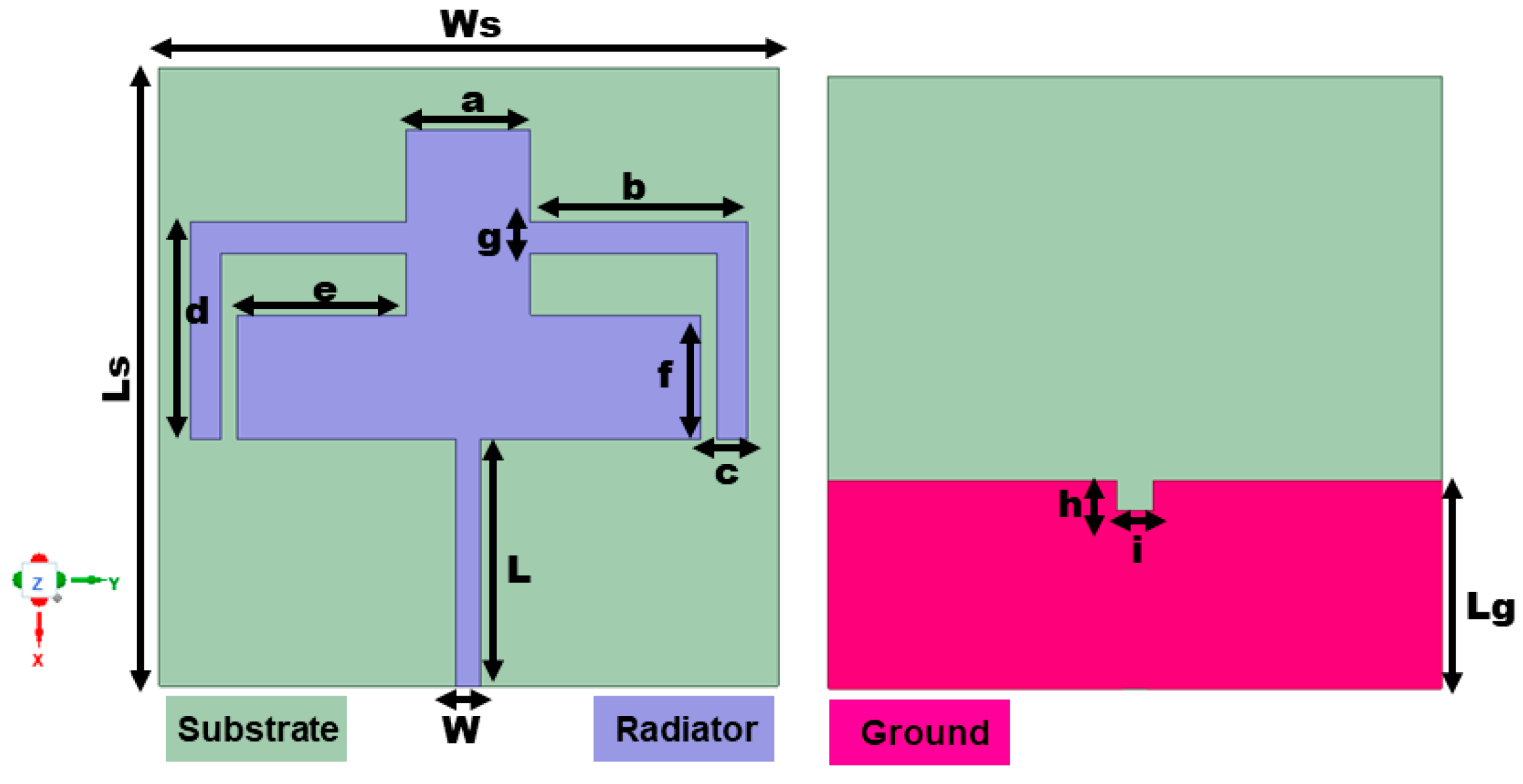
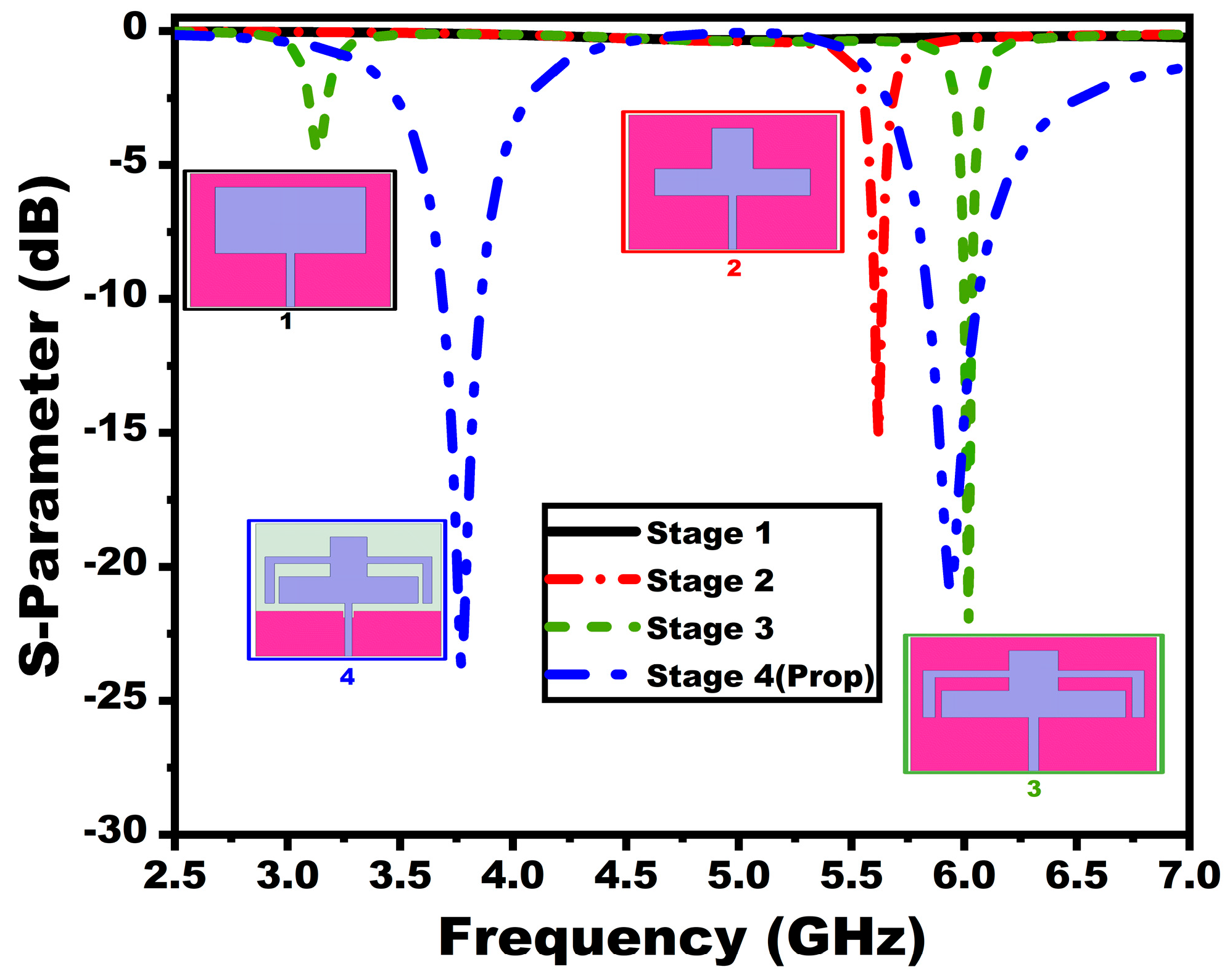
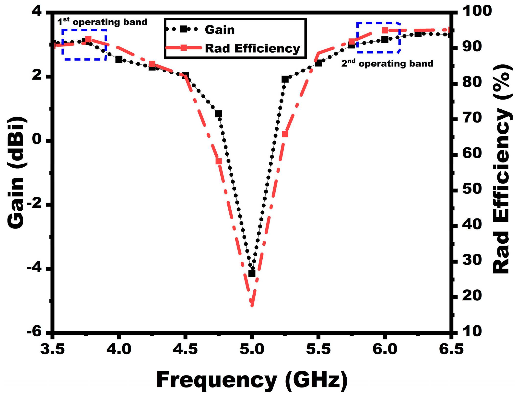
2.1. Design Methodology
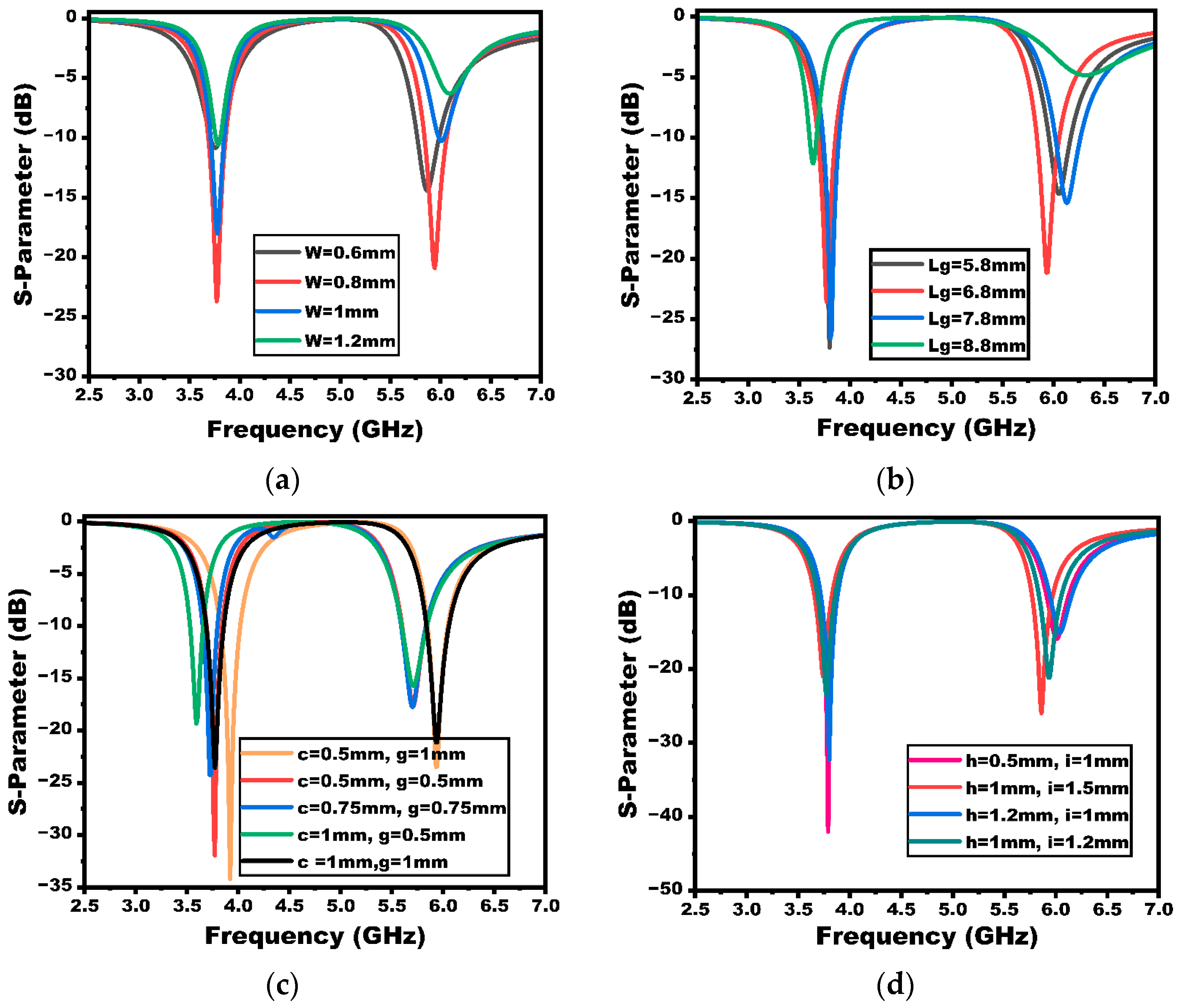
2.2. Parametric Study
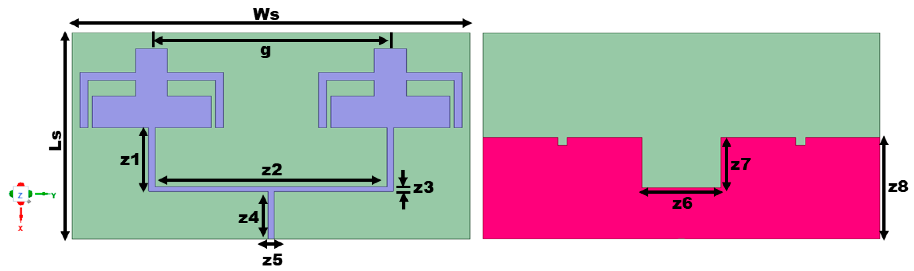
3. 1 × 2 Array Antenna
3.1. Design Methodology
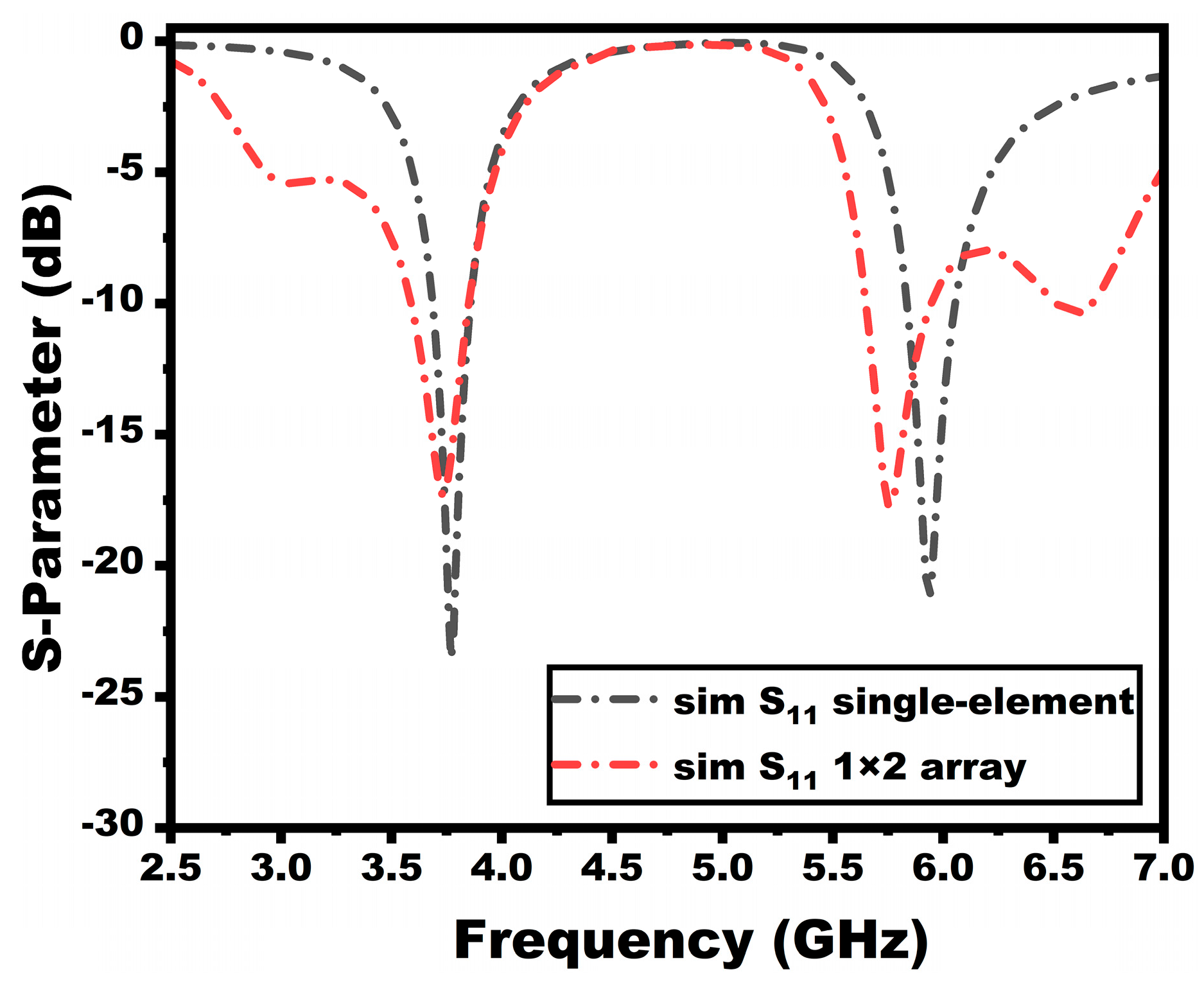
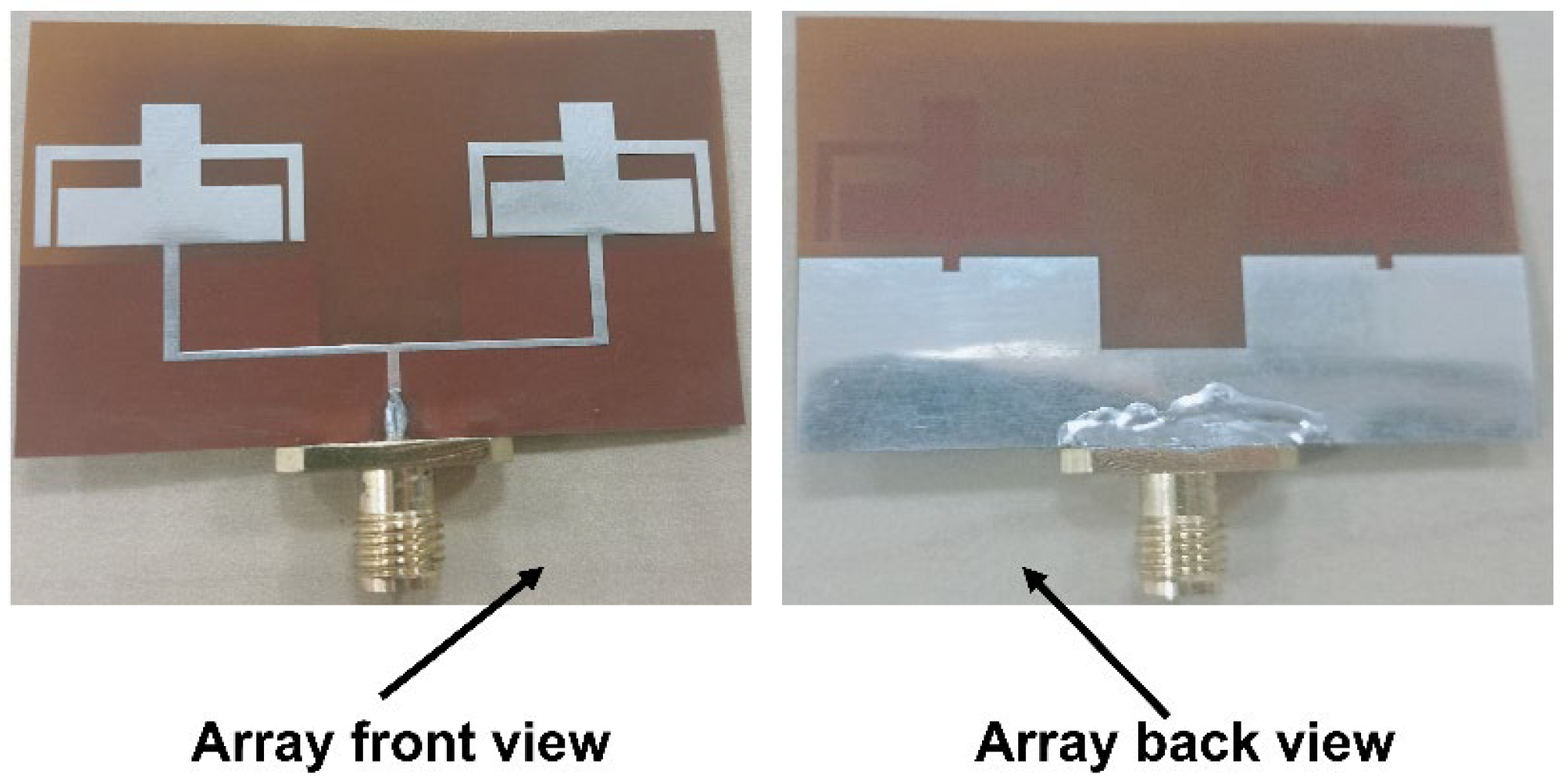
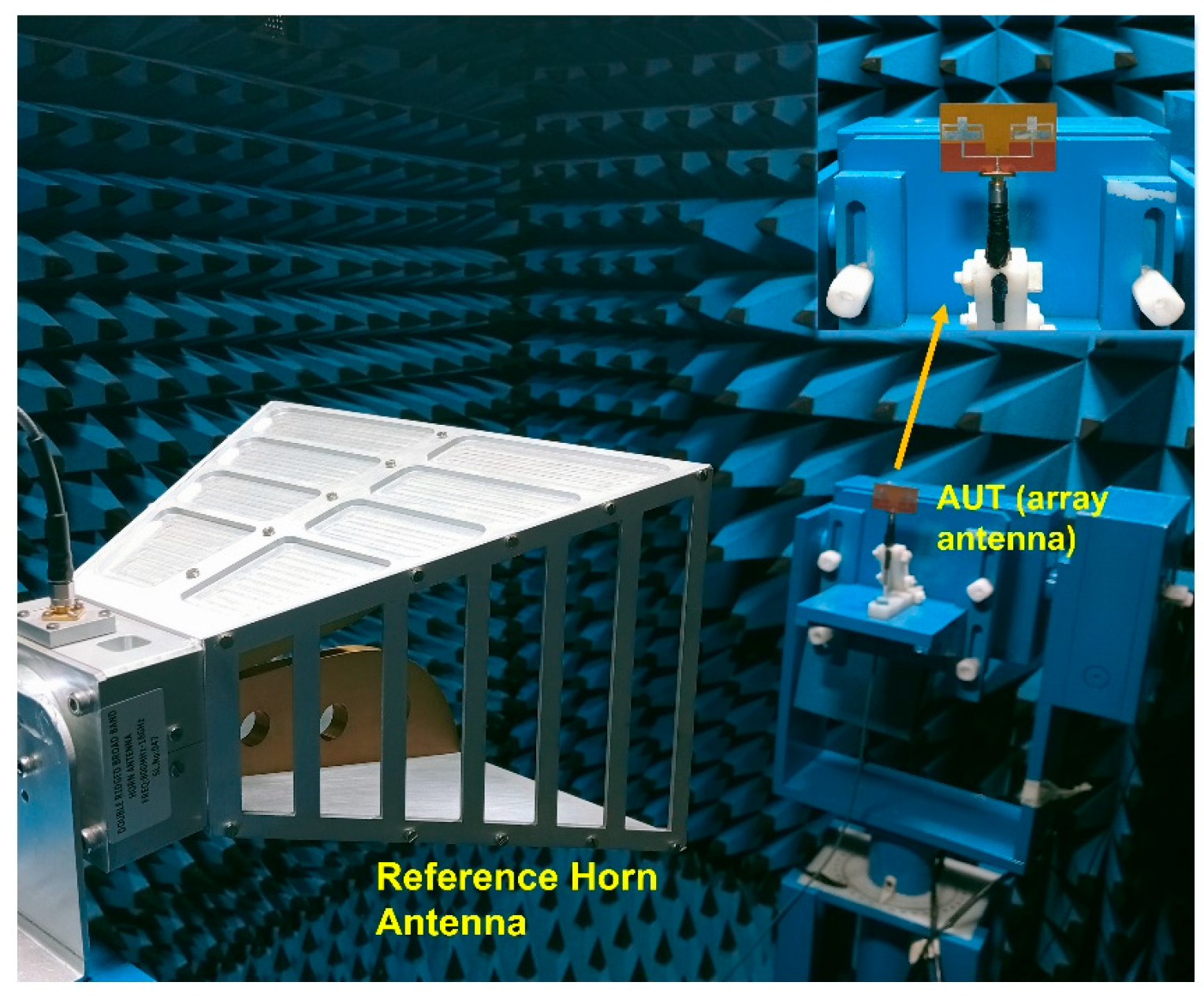
3.2. Measured Results and Discussion
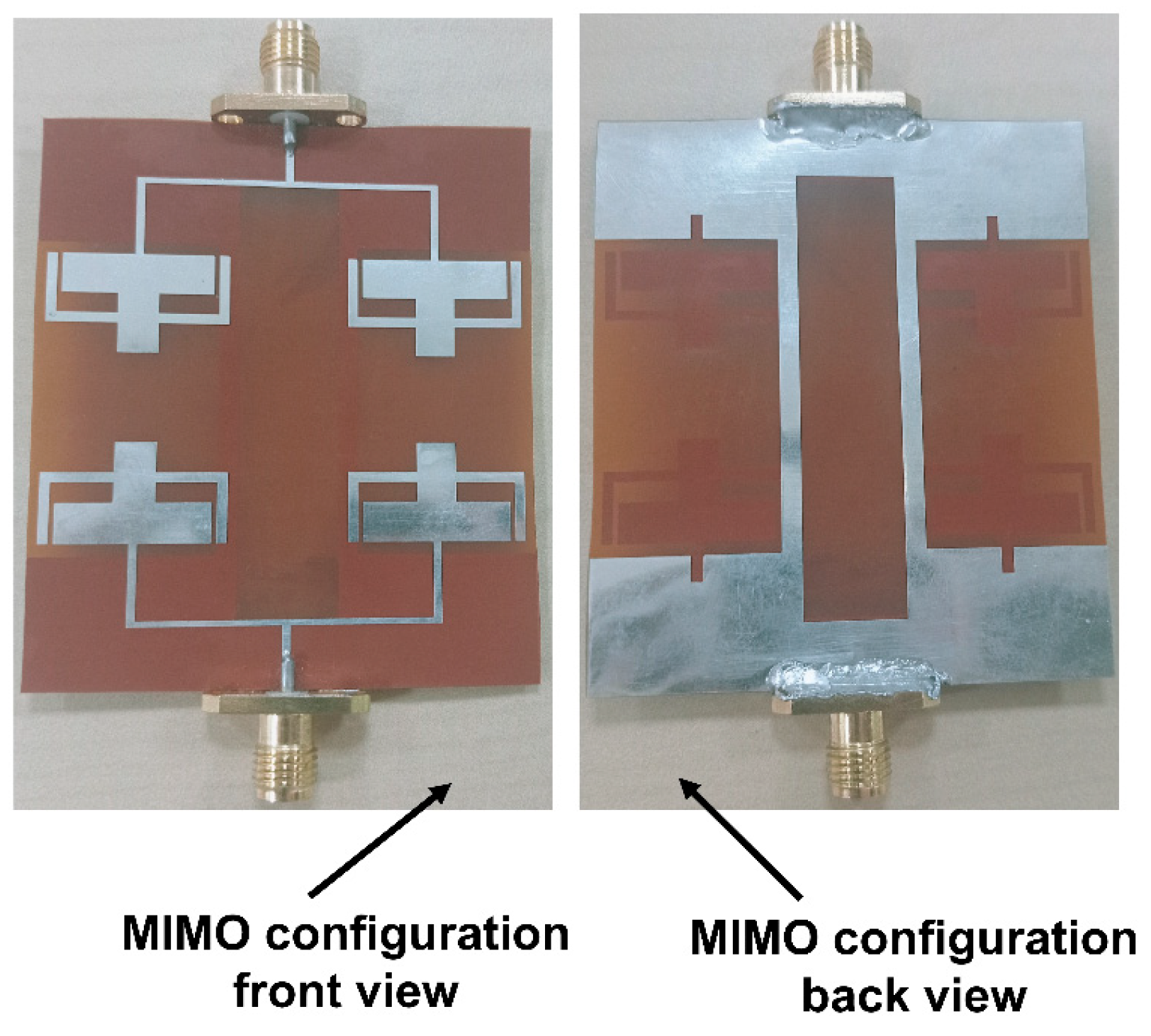
4. MIMO Array Antenna
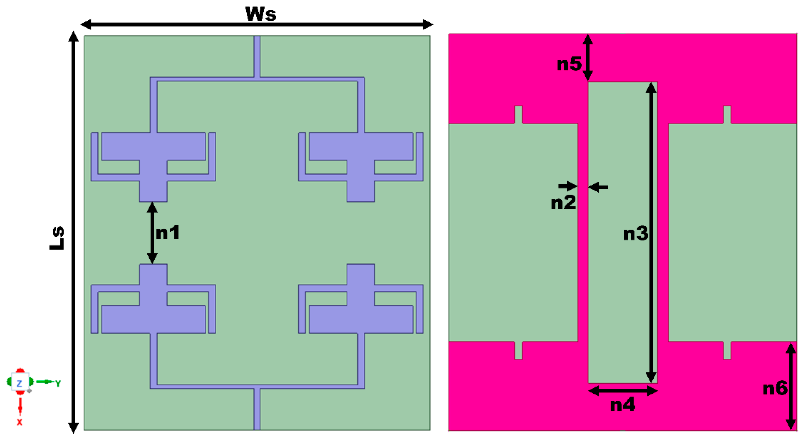
4.1. Methodology
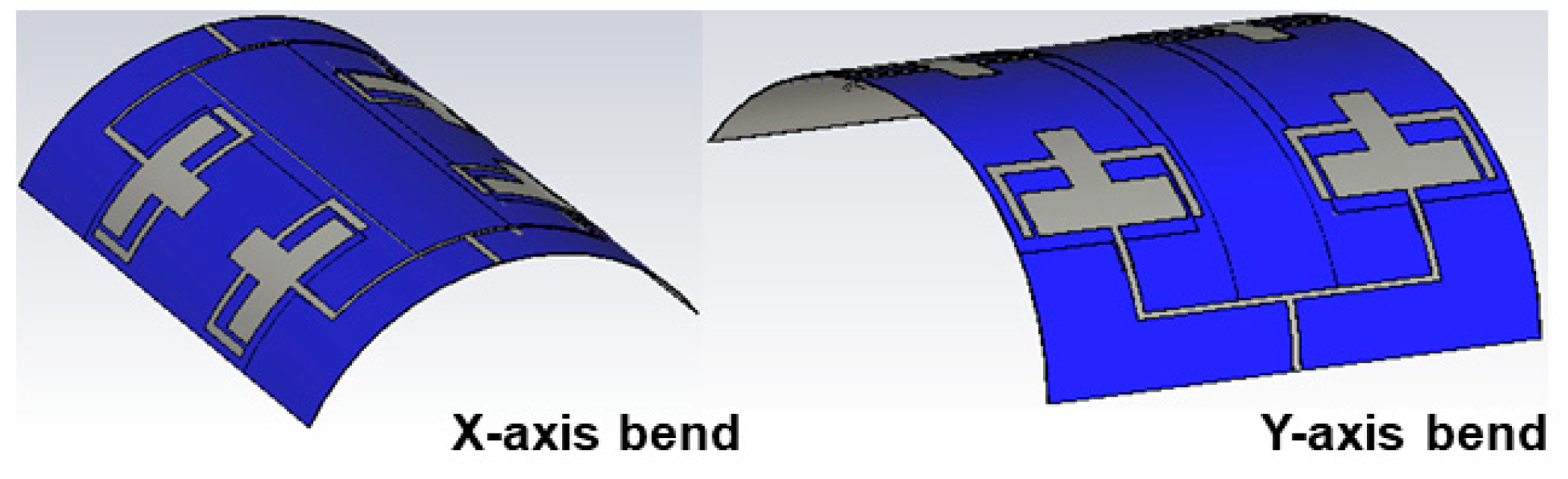
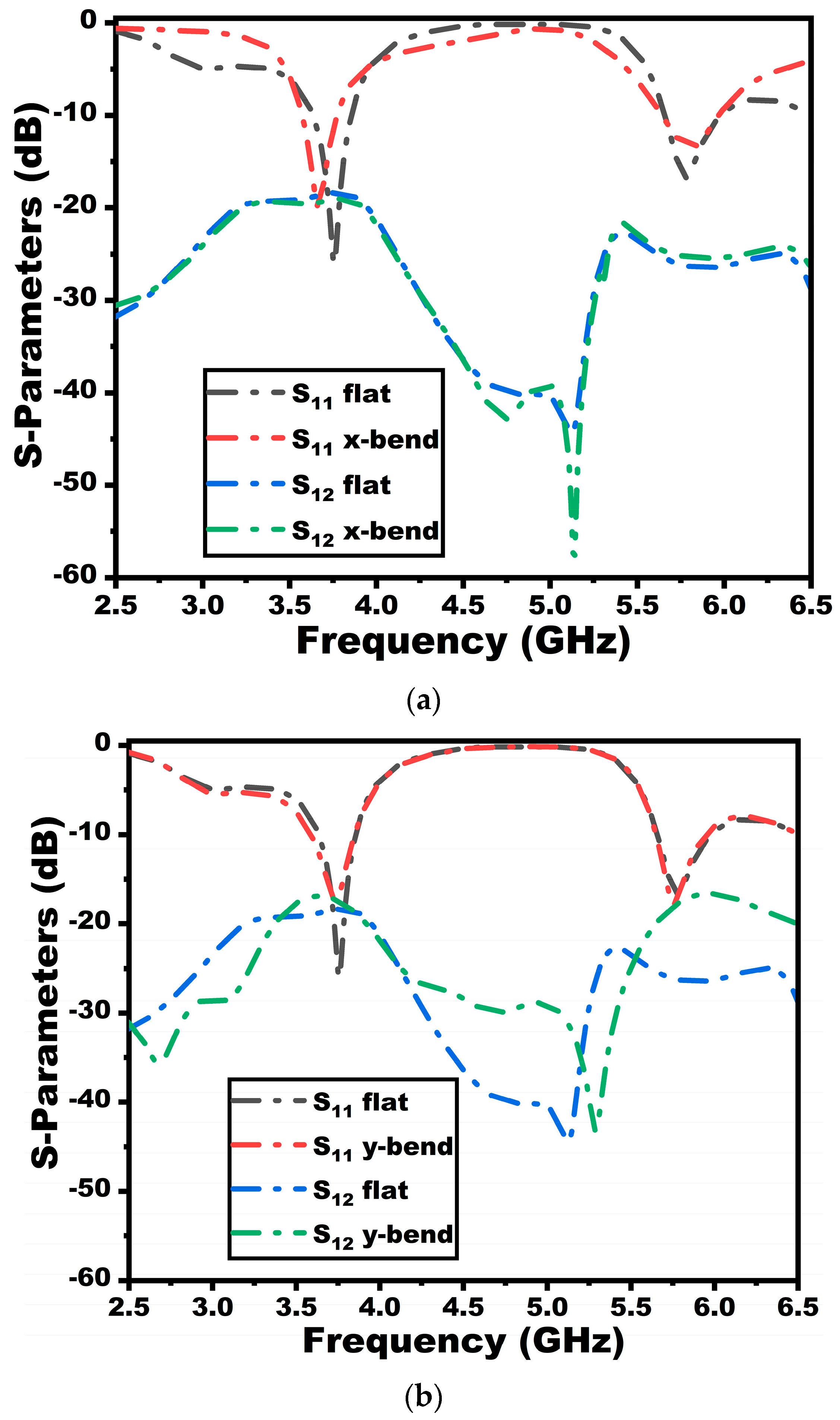
4.2. Bending Analysis of the Proposed Antenna
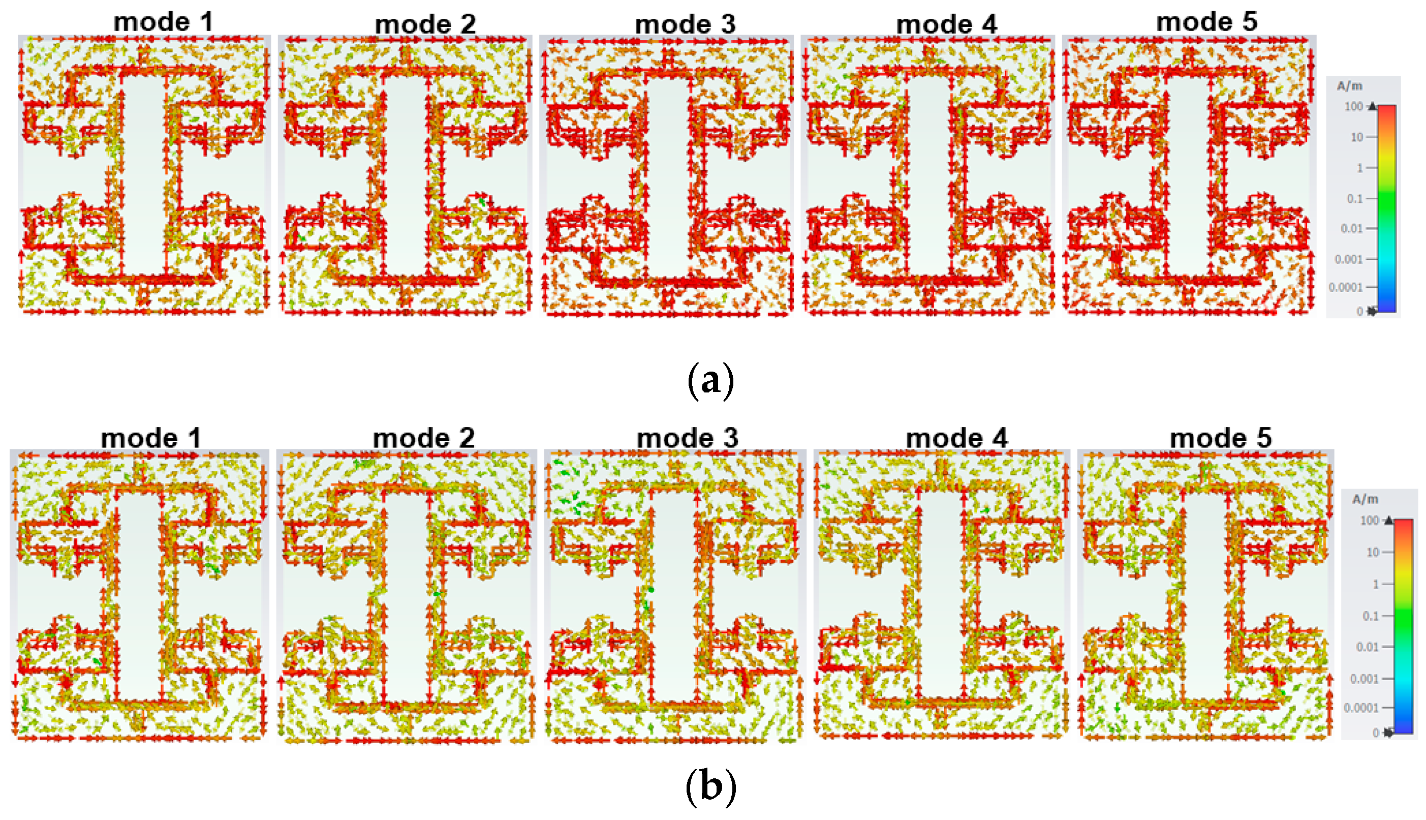
4.3. Characteristic Mode Analysis
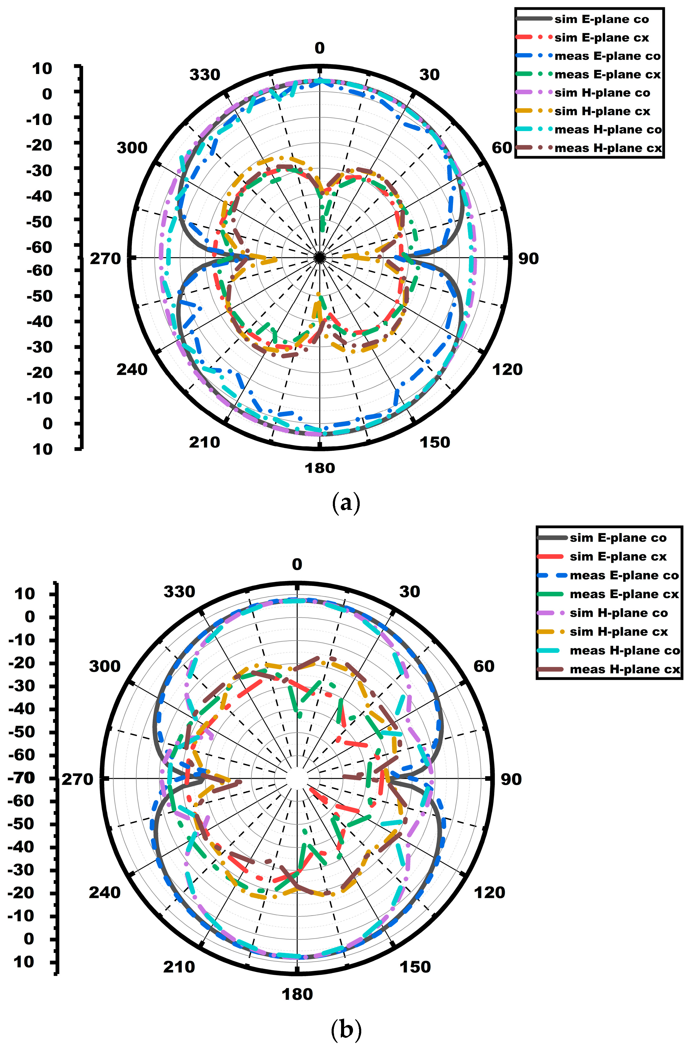
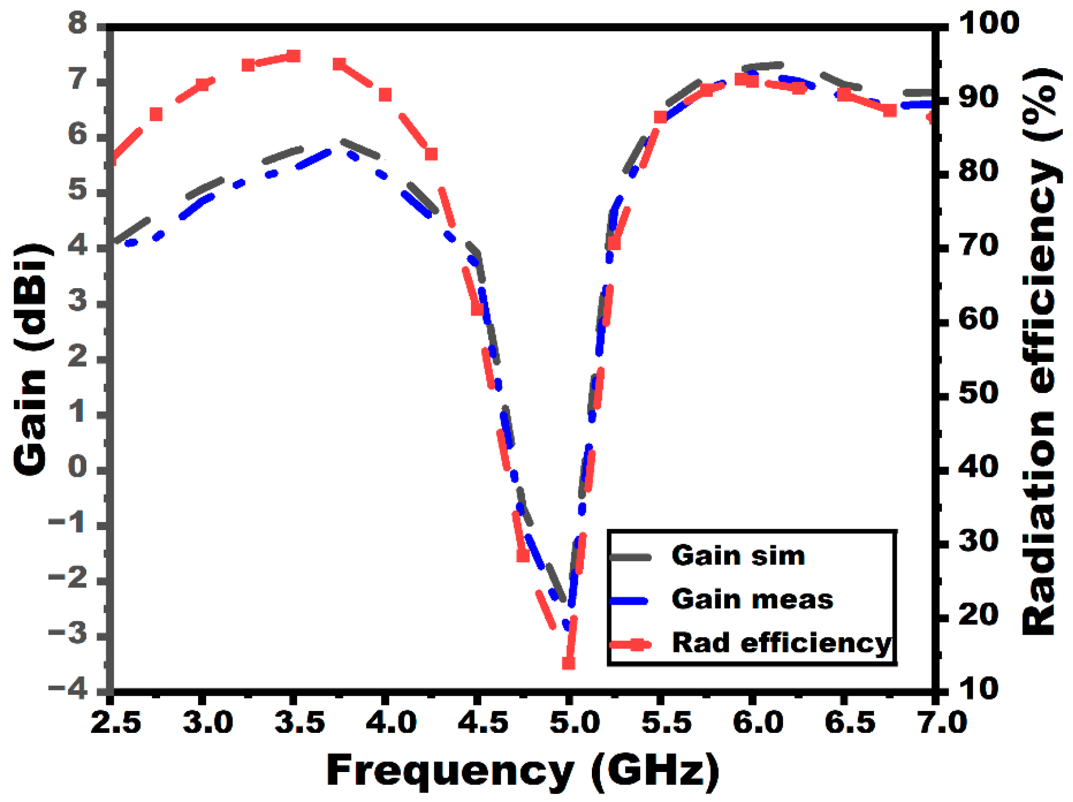
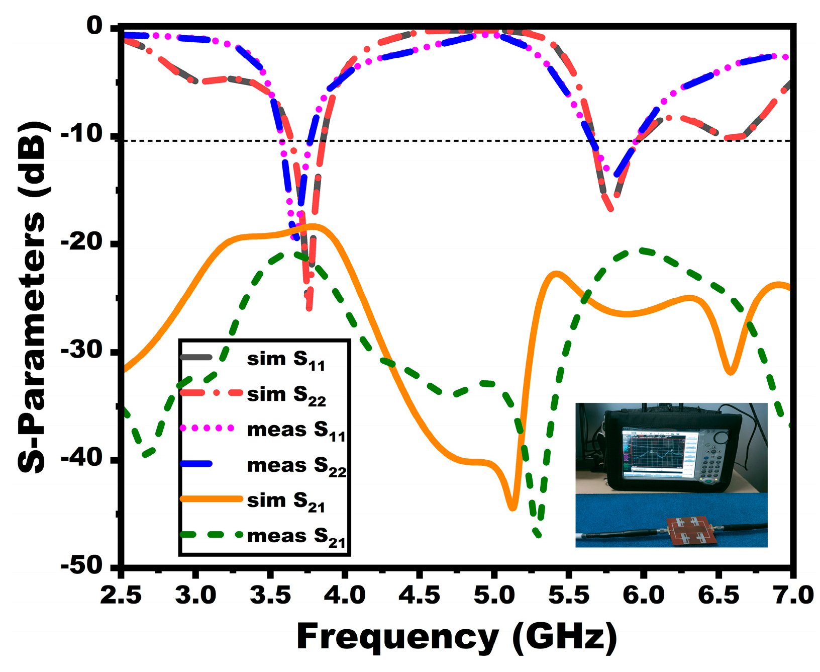
4.4. Results and Discussion
5. SAR Analysis of the MIMO Array Antenna
6. Comparative Study
7. Conclusions
Author Contributions
Funding
Institutional Review Board Statement
Informed Consent Statement
Data Availability Statement
Conflicts of Interest
References
- Feng, Y.; Yang, Y.; Zhang, L.-K.; Yang, Y.-H.; Zhou, S.-G.; Li, J.-Y.; Yang, G.-W. A 2-D Wideband and Wide Beam-Steering Phased Array Antenna With a Combined Superstrate for 5G Sub-6 GHz Applications. IEEE Trans. Circuits Syst. II Express Briefs 2024, 71, 3720–3724. [Google Scholar] [CrossRef]
- Nahar, T.; Rawat, S.; Pathak, P.; Kumar, P.; Anguera, J. Leaf-Shaped Antennas for Sub-6 GHz 5G Applications. IEEE Access 2024, 12, 114338–114357. [Google Scholar] [CrossRef]
- Agiwal, M.; Roy, A.; Saxena, N. Next Generation 5G Wireless Networks: A Comprehensive Survey. IEEE Commun. Surv. Tutor. 2016, 18, 1617–1655. [Google Scholar] [CrossRef]
- Ren, Z.; Wu, S.; Zhao, A. Triple band MIMO antenna system for 5G mobile terminals. In Proceedings of the 2019 International Workshop on Antenna Technology (iWAT), Miami, FL, USA, 3–6 March 2019; pp. 163–165. [Google Scholar]
- Xiao, Y.; Zu, H.; Song, R.; Xin, Y.; Xi, Y.; Huang, G.-L.; Wu, B.; He, D. Multiband and Low-Specific-Absorption-Rate Wearable Antenna With Low Profile Based on Highly Conductive Graphene Assembled Film. Antennas Wirel. Propag. Lett. 2023, 22, 2195–2199. [Google Scholar] [CrossRef]
- Kulkarni, J.; Alharbi, A.G.; Sim, C.-Y.; Elfergani, I.; Anguera, J.; Zebiri, C.; Rodriguez, J. Dual Polarized, Multiband Four-Port Decagon Shaped Flexible MIMO Antenna for Next Generation Wireless Applications. IEEE Access 2022, 10, 128132–128150. [Google Scholar] [CrossRef]
- Liu, P.; Meng, Z.; Wang, L.; Zhang, Y.; Li, Y. Omnidirectional Dual-Polarized Saber Antenna With Low Wind Drag. IEEE Trans. Antennas Propag. 2020, 68, 558–563. [Google Scholar] [CrossRef]
- Roy, S.; Chakraborty, U. Mutual Coupling Reduction in a Multi-band MIMO Antenna Using Meta-Inspired Decoupling Network. Wirel. Pers. Commun. 2020, 114, 3231–3246. [Google Scholar] [CrossRef]
- Li, Q.L.; Cheung, S.W.; Wu, D.; Yuk, T.I. Optically Transparent Dual-Band MIMO Antenna Using Micro-Metal Mesh Conductive Film for WLAN System. Antennas Wirel. Propag. Lett. 2017, 16, 920–923. [Google Scholar] [CrossRef]
- Hasan, M.M.; Islam, M.T.; Samsuzzaman; Baharuddin, M.H.; Soliman, M.S.; Alzamil, A.; Abu Sulayman, I.I.M.; Islam, S. Gain and isolation enhancement of a wideband MIMO antenna using metasurface for 5G sub-6 GHz communication systems. Sci. Rep. 2022, 12, 9433. [Google Scholar] [CrossRef]
- Khan, J.; Ullah, S.; Ali, U.; Tahir, F.A.; Peter, I.; Matekovits, L. Design of a Millimeter-Wave MIMO Antenna Array for 5G Communication Terminals. Sensors 2022, 22, 2768. [Google Scholar] [CrossRef]
- Kamal, M.M.; Yang, S.; Kiani, S.H.; Sehrai, D.A.; Alibakhshikenari, M.; Abdullah, M.; Falcone, F.; Limiti, E.; Munir, M. A Novel Hook-Shaped Antenna Operating at 28 GHz for Future 5G mmwave Applications. Electronics 2021, 10, 673. [Google Scholar] [CrossRef]
- Khan, J.; Ullah, S.; Tahir, F.A.; Tubbal, F.; Raad, R. A Sub-6 GHz MIMO Antenna Array for 5G Wireless Terminals. Electronics 2021, 10, 3062. [Google Scholar] [CrossRef]
- Alwareth, H.; Ibrahim, I.M.; Zakaria, Z.; Al-Gburi, A.J.A.; Ahmed, S.; Nasser, Z.A. A Wideband High-Gain Microstrip Array Antenna Integrated with Frequency-Selective Surface for Sub-6 GHz 5G Applications. Micromachines 2022, 13, 1215. [Google Scholar] [CrossRef] [PubMed]
- John, D.M.; Vincent, S.; Pathan, S.; Ali, T. A compact highly flexible two-element wideband MIMO antenna based on modal analysis for 5G wireless applications. Phys. Scr. 2024, 99, 075535. [Google Scholar] [CrossRef]
- Kulkarni, N.; Linus, R.M.; Bahadure, N.B. A small wideband inverted l-shaped flexible antenna for sub-6 GHz 5G applications. AEU Int. J. Electron. Commun. 2023, 159, 154479. [Google Scholar] [CrossRef]
- Desai, A.; Palandoken, M.; Kulkarni, J.; Byun, G.; Nguyen, T.K. Wideband Flexible/Transparent Connected-Ground MIMO Antennas for Sub-6 GHz 5G and WLAN Applications. IEEE Access 2021, 9, 147003–147015. [Google Scholar] [CrossRef]
- Abdelghany, M.A.; Ibrahim, A.A.; Mohamed, H.A.; Tammam, E. Compact Sub-6 GHz Four-Element Flexible Antenna for 5G Applications. Electronics 2024, 13, 537. [Google Scholar] [CrossRef]
- Elias, B.B.Q.; Soh, P.J.; Al-Hadi, A.A.; Akkaraekthalin, P.; Vandenbosch, G.A.E. A Review of Antenna Analysis Using Characteristic Modes. IEEE Access 2021, 9, 98833–98862. [Google Scholar] [CrossRef]
- Kempanna, S.B.; Biradar, R.C.; Kumar, P.; Kumar, P.; Pathan, S.; Ali, T. Characteristic-Mode-Analysis-Based Compact Vase-Shaped Two-Element UWB MIMO Antenna Using a Unique DGS for Wireless Communication. J. Sens. Actuator Netw. 2023, 12, 47. [Google Scholar] [CrossRef]
- Kumar, P.; Sivakumar, V.; Rao, V.; George, C.T.; Awadhiya, B.; Huchegowda, Y.B.; Nanjappa, Y. A defected ground structure based ultra-compact wider bandwidth terahertz multiple-input multiple-output antenna for emerging communication systems. Heliyon 2024, 10, e36842. [Google Scholar] [CrossRef]
- IT’IS Foundation. Dielectric Properties. Available online: https://itis.swiss/virtual-population/tissue-properties/database/dielectric-properties/ (accessed on 3 January 2024).
- Sim, C.-Y.-D.; Liu, H.-Y.; Huang, C.-J. Wideband MIMO Antenna Array Design for Future Mobile Devices Operating in the 5G NR Frequency Bands n77/n78/n79 and LTE Band 46. IEEE Antennas Wirel. Propag. Lett. 2020, 2020 19, 74–78. [Google Scholar] [CrossRef]
- Zheng, Z.; Ntawangaheza, J.D.; Sun, L. Wideband MIMO Antenna System for Sub-6 GHz Cell Phone. In Proceedings of the 2021 International Conference on Electronics, Circuits and Information Engineering (ECIE), Zhengzhou, China, 22–24 January 2021; pp. 1–5. [Google Scholar] [CrossRef]


| Parameter | Ws | Ls | W | L | Lg | a | b | c | d | e | f | g | h | i |
|---|---|---|---|---|---|---|---|---|---|---|---|---|---|---|
| Value (in mm) | 20 | 20 | 0.8 | 8 | 6.8 | 4 | 7 | 1 | 7 | 5.5 | 4 | 1 | 1 | 1.2 |
| Parameter | Ws | Ls | g | z1 | z2 | z3 | z4 | z5 | z6 | z7 | z8 |
|---|---|---|---|---|---|---|---|---|---|---|---|
| Value (in mm) | 50 | 26 | 30 | 8 | 29 | 0.55 | 6 | 0.8 | 10 | 6.4 | 12.8 |
| Ref. | Dimension (mm3) | Impedance Bandwidth (GHz) | I* (dB) | Flexibility | ECC | DG | MEG | TARC | SAR (W/kg) |
|---|---|---|---|---|---|---|---|---|---|
| [2] | 49.09 × 25 × 1.6 | 3.30–3.85 | 10 | No | ~0 | ~10 | 0 dB (ratio) | <−10 | - |
| [4] | 150 × 75 × 0.8 | 3.3–4.2 4.4–5 5.15–5.85 | 14 | No | <0.05 | - | - | - | - |
| [13] | 160 × 70 × 0.787 | 5.60–5.67 | 30 | No | <0.5 | ~10 | - | - | 0.0989 (10 g) 0.101(1 g) |
| [23] | 103.8 × 68 × 7 | 3.55–4.2 3.6–4.9 5.15–5.925 | 10 | No | <0.1 | - | - | - | - |
| [24] | 150 × 75 × 7 | 3.3–3.8 4.1–5.8 | 15 | No | <0.03 | - | - | <−10 | 0.179 (1 g) |
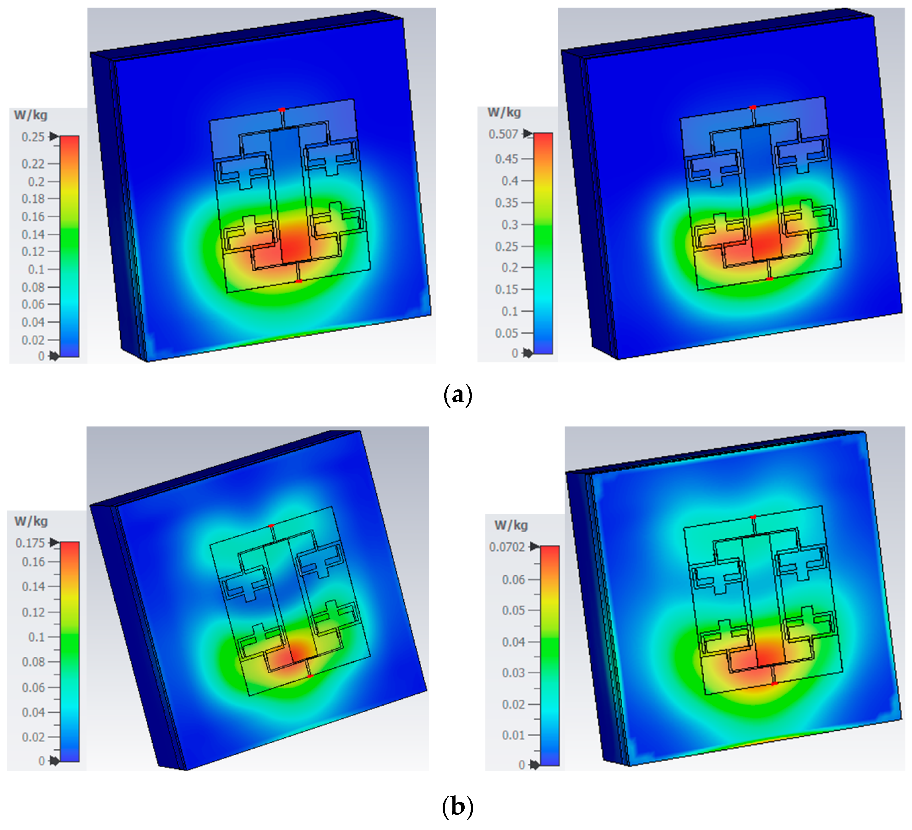
| Prop | 57 × 50 × 0.1 | 3.6–3.8 5.65–5.95 | 22 | Yes | <0.05 | >9.99 | −3 dB | <−10 | At 3.75 GHz 0.0702 (1 g) 0.25 (10 g) At 5.9 GHz 0.175 (1 g) 0.507 (10 g) |
Disclaimer/Publisher’s Note: The statements, opinions and data contained in all publications are solely those of the individual author(s) and contributor(s) and not of MDPI and/or the editor(s). MDPI and/or the editor(s) disclaim responsibility for any injury to people or property resulting from any ideas, methods, instructions or products referred to in the content. |
© 2025 by the authors. Licensee MDPI, Basel, Switzerland. This article is an open access article distributed under the terms and conditions of the Creative Commons Attribution (CC BY) license (https://creativecommons.org/licenses/by/4.0/).
Share and Cite
John, D.M.; Ali, T.; Vincent, S.; Pathan, S.; Anguera, J.; Virdee, B.; David, R.M.; Nayak, K.; Puthenveettil Gopi, S. A Dual-Band Flexible MIMO Array Antenna for Sub-6 GHz 5G Communications. Sensors 2025, 25, 3557. https://doi.org/10.3390/s25113557
John DM, Ali T, Vincent S, Pathan S, Anguera J, Virdee B, David RM, Nayak K, Puthenveettil Gopi S. A Dual-Band Flexible MIMO Array Antenna for Sub-6 GHz 5G Communications. Sensors. 2025; 25(11):3557. https://doi.org/10.3390/s25113557
Chicago/Turabian StyleJohn, Deepthi Mariam, Tanweer Ali, Shweta Vincent, Sameena Pathan, Jaume Anguera, Bal Virdee, Rajiv Mohan David, Krishnamurthy Nayak, and Sudheesh Puthenveettil Gopi. 2025. "A Dual-Band Flexible MIMO Array Antenna for Sub-6 GHz 5G Communications" Sensors 25, no. 11: 3557. https://doi.org/10.3390/s25113557
APA StyleJohn, D. M., Ali, T., Vincent, S., Pathan, S., Anguera, J., Virdee, B., David, R. M., Nayak, K., & Puthenveettil Gopi, S. (2025). A Dual-Band Flexible MIMO Array Antenna for Sub-6 GHz 5G Communications. Sensors, 25(11), 3557. https://doi.org/10.3390/s25113557