

Single-Crystal Inspection Using an Adapted Total Focusing Method
 , , ,
, , , 
Abstract
1. Introduction
2. Methodology
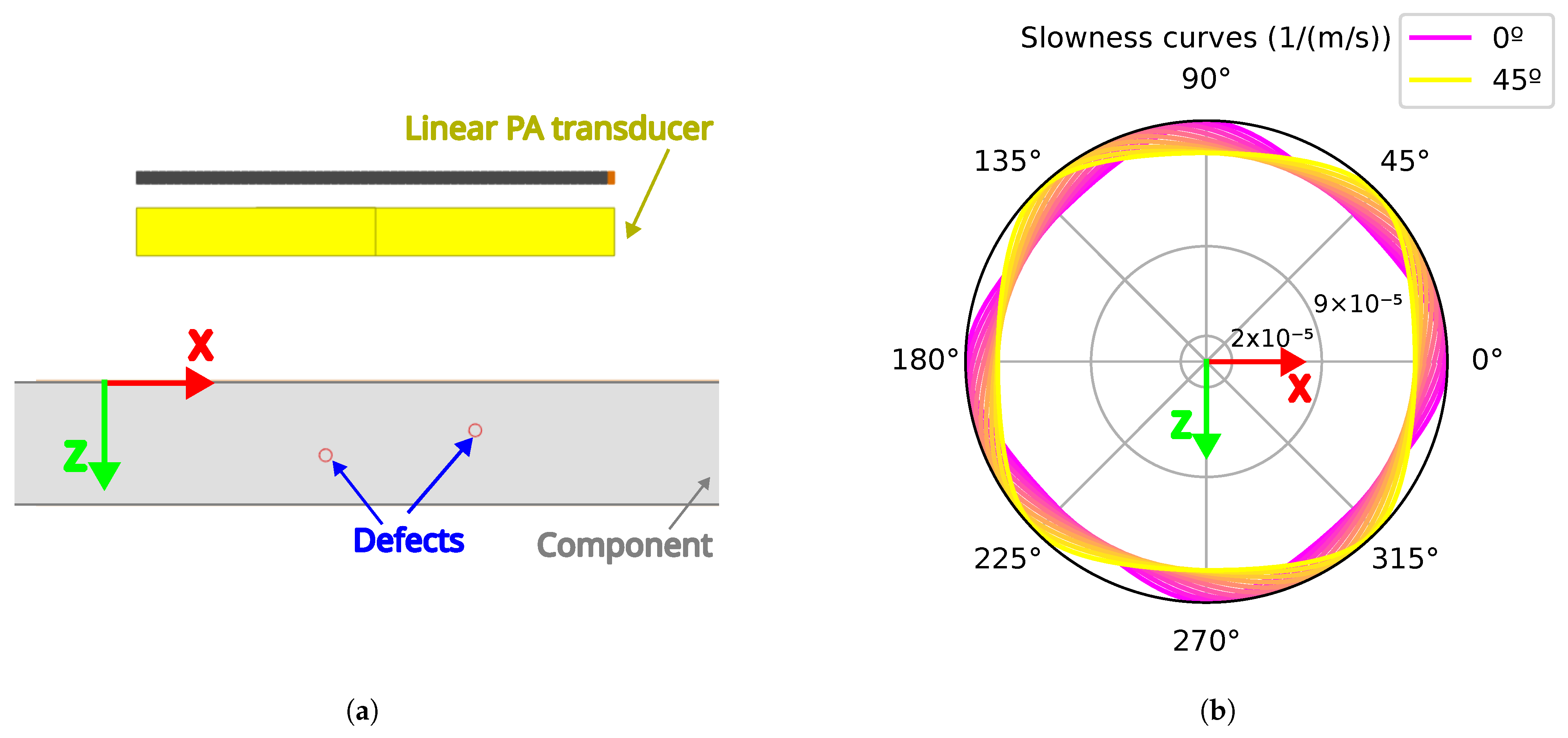
2.1. FMC Data Generation
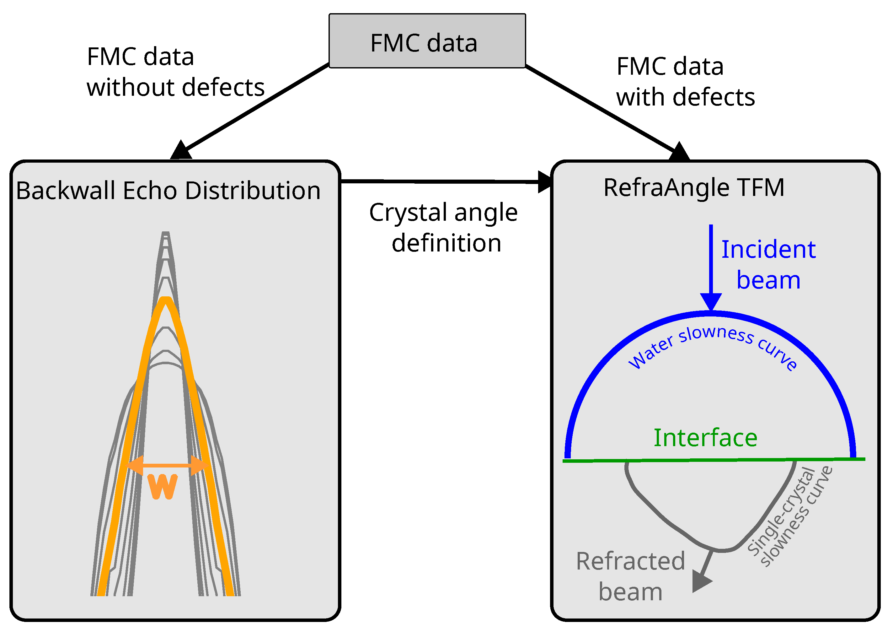
2.2. Backwall Echo Distribution
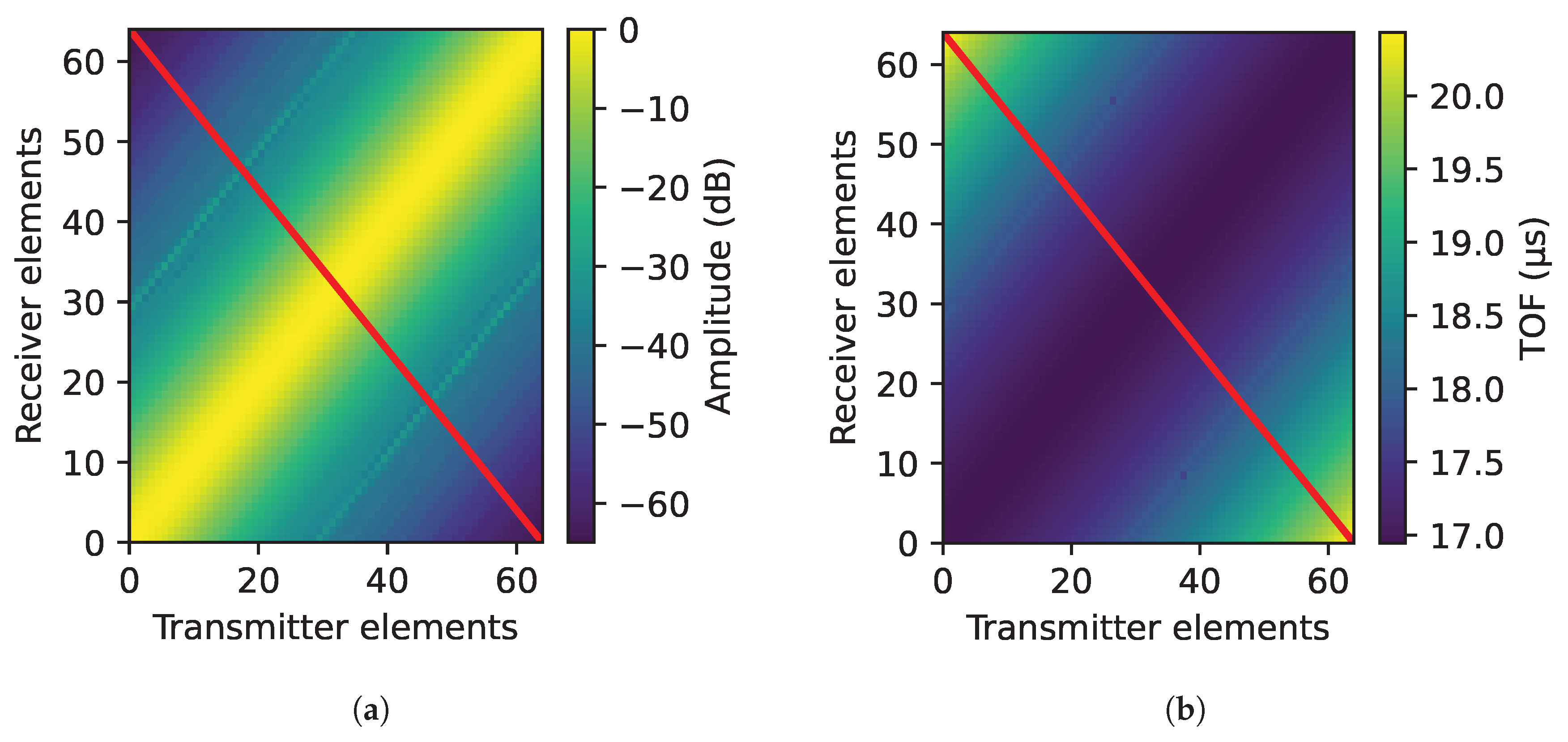
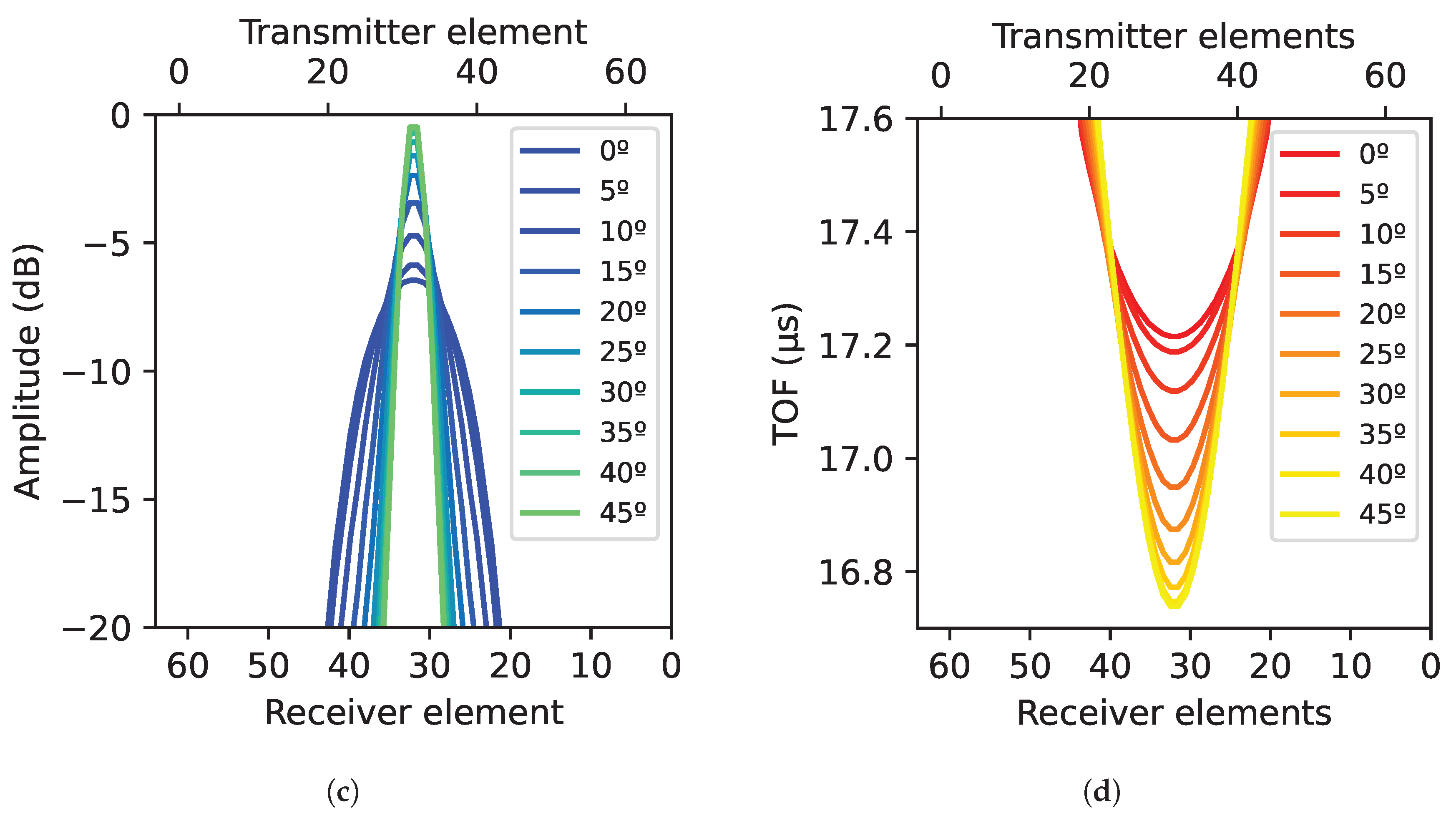
- From the ultrasonic data matrix generated by the FMC technique, the results obtained for each crystal angulation were compared by analyzing the Ascans corresponding to tx = N − rx combinations, where tx refers to the transmitting element, rx to the receiving element and N to the number of elements of the linear PA.
- In each Ascan, the response of the backwall echo was extracted by defining a gate from to based on the thickness of the component.
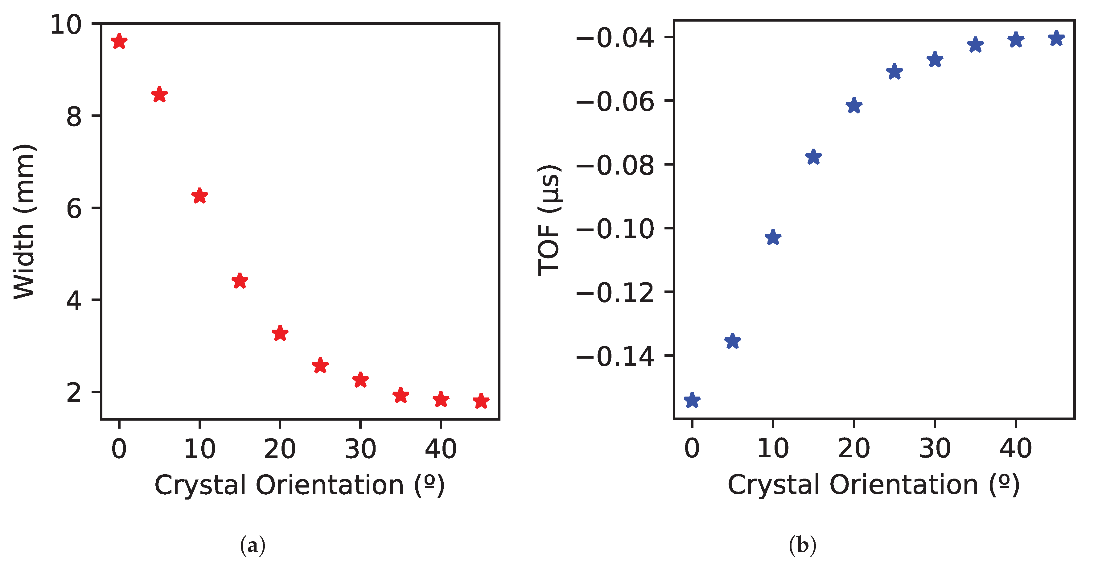
- The different widths of the generated ultrasonic beam were determined based on −6 dB attenuation of the maximum signal. The transmitters that produced a response with a 6 dB attenuation from the maximum were identified based on Equation (3).
2.3. TFM Algorithm Implementation
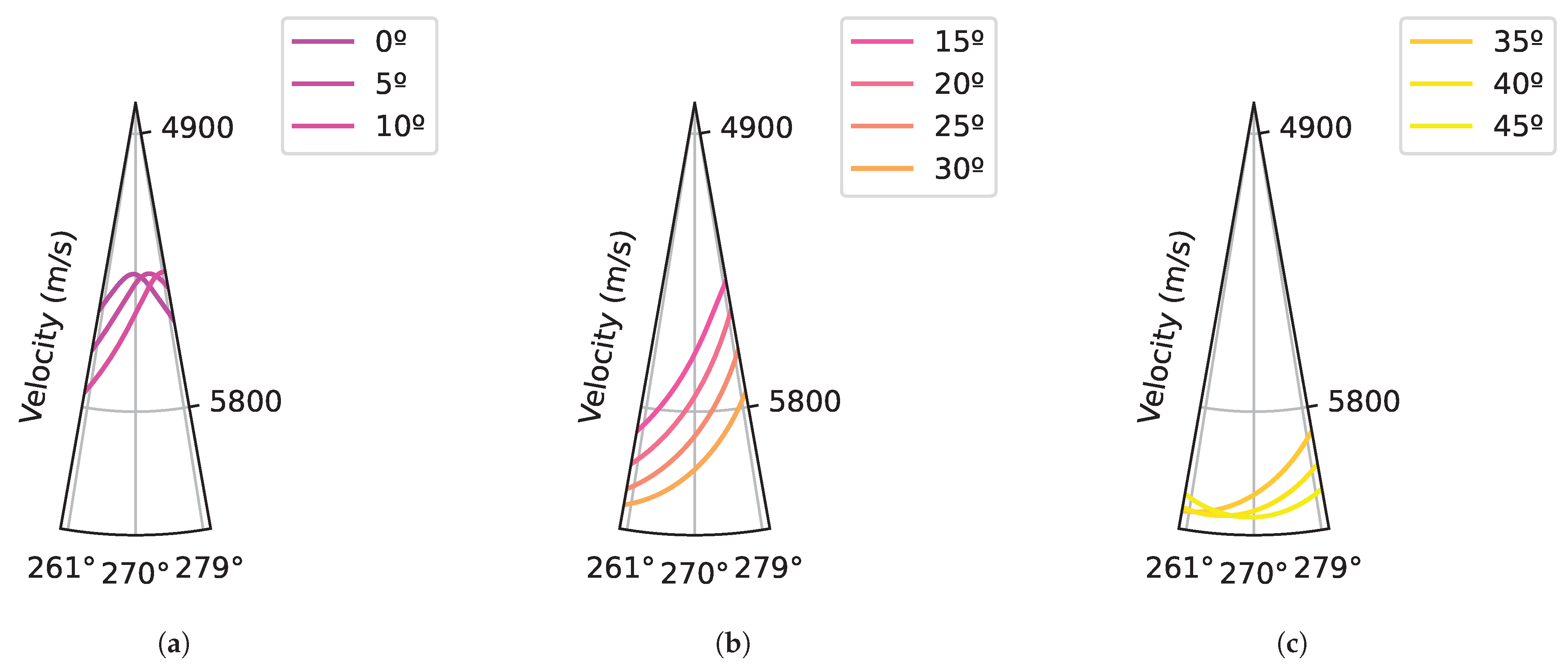
- Velocity: The stiffness matrix defined in Table 1 was used to calculate the slowness curves by Christoffel’s Equation (5), where, is the Kronecker symbol, V is the phase velocity, n is the propagation direction, and is the single-crystal stiffness matrix.On the one hand, the isotropic approach assumes a constant mean velocity of slowness curves. On the other hand, the anisotropic approach considers velocity variations as a function of the propagation angle.
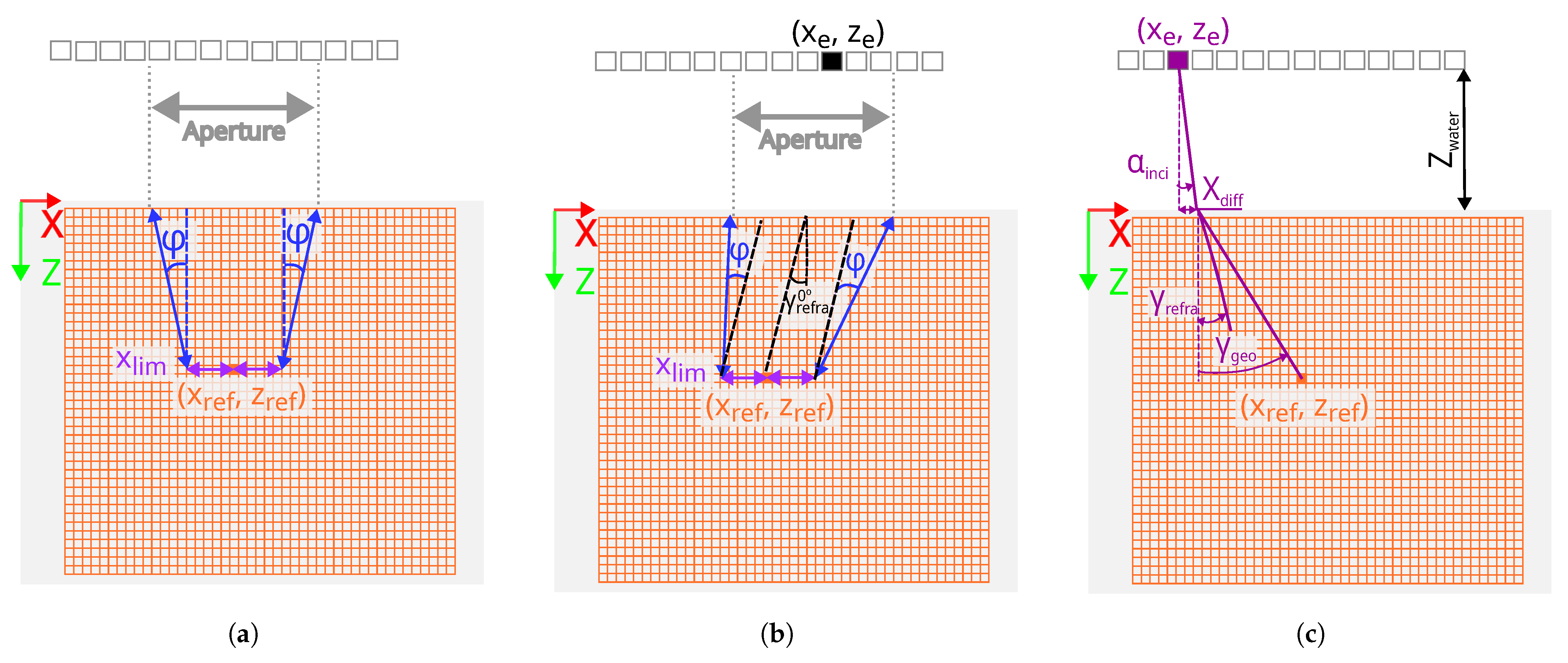
- Filter: The filter defines the number of elements or aperture considered in each reconstruction grid. In the classical approaches, the conventional filters and slope (tan (φ)) [27] are considered. and slope are defined based on the beam divergence. In Figure 4a, the linear transducer and the component with the reconstruction grid are presented. The grid (, ) has been highlighted and the aperture has been calculated based on and slope parameters. As shown in Figure 4a, the filter is symmetrical to the grid point. On the other hand, in the proposed approaches,“Strategy A” and “Strategy B”, the RefraFilter (see Figure 4b) has been defined, which is not symmetrical with respect to the pixel. The contribution of the RefraFilter to the optimization of the TFM reconstruction is explained in detail in “Strategy A”.
- Interface: For the classical approaches and “Strategy A”, the interface point of the beam between the coupling medium and the component was calculated using Fermat’s minimum time principle. According to this principle, the wave propagation through the water/solid interface must correspond to the minimum propagation time [28,29]. To further optimize inspection results, “Strategy B” introduces RefraRecons, which is the second key contribution aimed at enhancing the effectiveness of the inspection process. The contribution of RefraRecons is explained in detail in “Strategy B”.
- Strategy A: The Fermat principle of minimum time and velocity variation have been calculated as in “Strategy Ani”. However, in order to reduce the noise considering the beam directivity, the RefraFilter has been designed based on the refraction angle at a 0° incidence angle instead of using the conventional filters and slope (tan ()). The refraction angle at 0° depends on the single-crystal orientation and it has been calculated based on Christoffel’s equation and the Fermat principle of stationary time considering the phase velocity. The Fermat principle of stationary time states that at the interface between two media, the horizontal component of phase slowness must remain continuous across the interface. This property must be preserved for both isotropic and anisotropic media regardless of the nature of the waves generated in the boundary [28,30]. Figure 4b represents a linear PA transducer with a component with a grid where a point (, ) has been highlighted. In addition, at a 0° angle of incidence is represented and the filter is defined based on this. The filters described in Equations (6) and (7) have been applied, where and correspond to each position of the TFM reconstruction grid, corresponds to the PA elements at the X position, and corresponds to the refracted angle at 0°.
- Strategy B: The variation in the refraction angle as a function of the crystal orientation has been taken into account, as in “Strategy Ani” and “Strategy A”. However, a different method has been implemented to determine the water/solid interface point, replacing the use of Fermat’s minimum time principle. In “Strategy B”, the interface point is identified as the location that produces a refracted angle closest to the energy refracted angle. Iteration with different incident angles has been performed to determine the interface point between the water and the component. To achieve this, the incidence angle has been varied from −5° to 5° in 0.05° increments. Equation (8) defines the , which is the X-axis distance of the beam in the water, where corresponds to the incidence angle in the water and corresponds to the water distance in the Z-axis (see Figure 4c).For each incidence angle, a geometrical angle in the component, , has been defined (see Equation (9)), where and correspond to the X and Z positions of the reconstruction pixel, and corresponds to the PA elements’ X position (see Figure 4c).The geometrical angle,, has been compared to the refracted angle, , obtained through slowness curves applying the Fermat principle of stationary time for each incidence angle. The incidence angle, which presents the minimum difference, has been selected, (see Equation (10)). The ultrasonic path has been calculated with the selected incident angle.
3. Results and Discussion
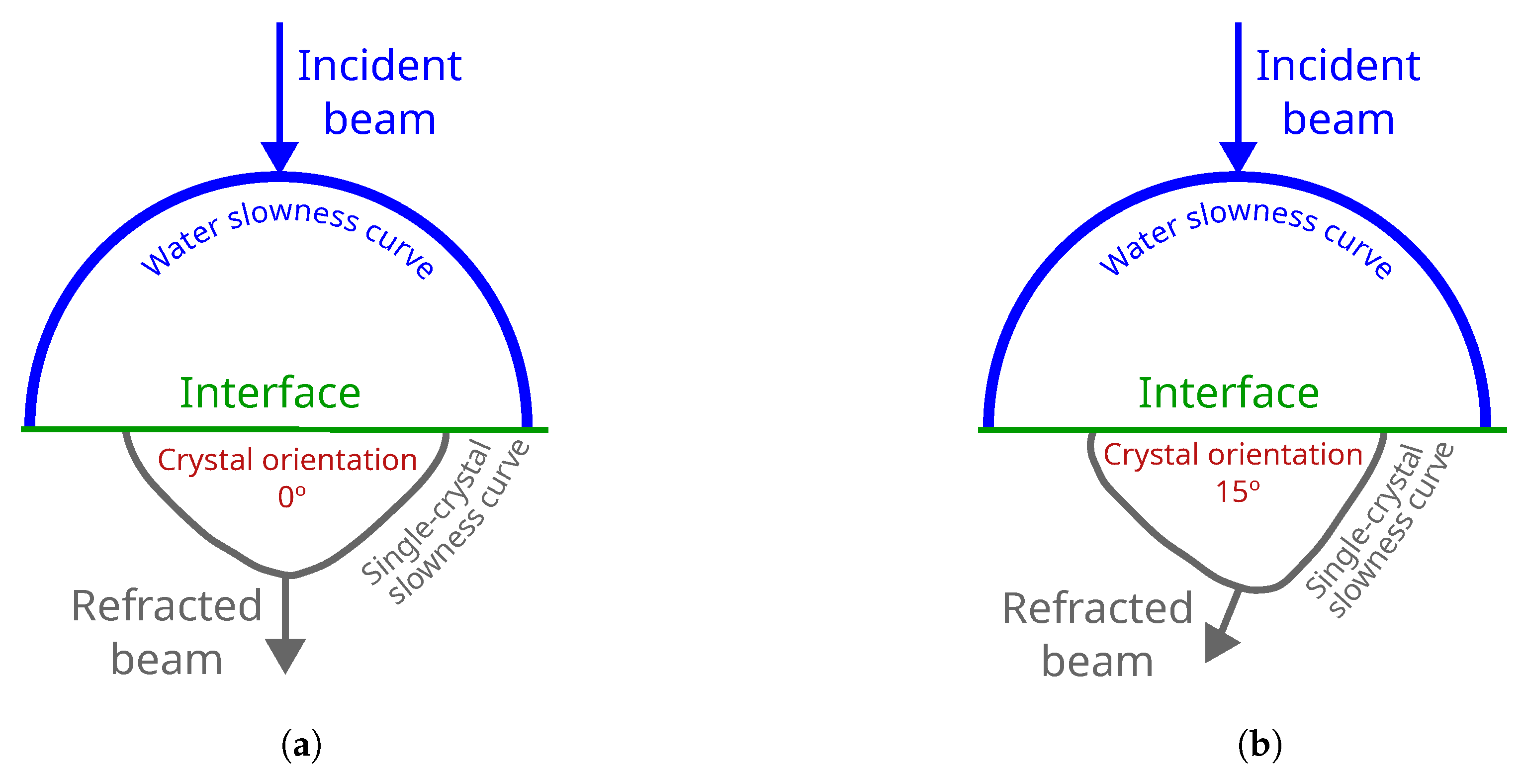
3.1. Crystal Angle Definition: Backwall Beam Distribution
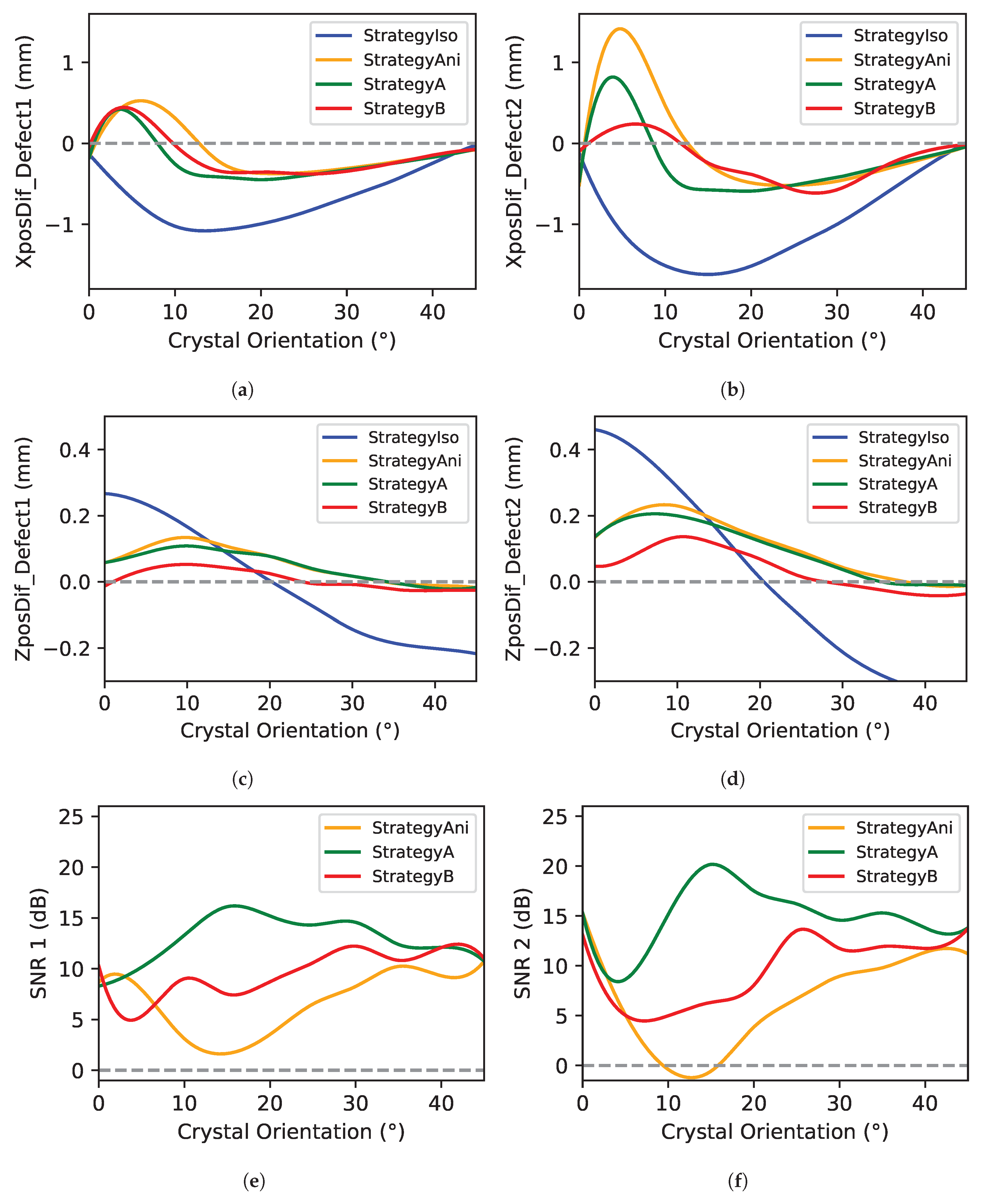
3.2. TFM Algorithm Reconstruction
4. Conclusions
Author Contributions
Funding
Institutional Review Board Statement
Informed Consent Statement
Data Availability Statement
Conflicts of Interest
References
- Callister, W.D., Jr.; Rethwisch, D.G. Materials Science and Engineering: An Introduction; John wiley & sons: Hoboken, NJ, USA, 2020. [Google Scholar]
- Angel, N.M.; Basak, A. On the fabrication of metallic single crystal turbine blades with a commentary on repair via additive manufacturing. J. Manuf. Mater. Process. 2020, 4, 101. [Google Scholar] [CrossRef]
- Hashmi, S.; Ferreira Batalha, G.; Van Tyne, C.J.; Yilbas, B.S. Comprehensive Materials Processing; Elsevier: Amsterdam, The Netherlands, 2014. [Google Scholar]
- Liu, D.; Ding, Q.; Yao, X.; Wei, X.; Zhao, X.; Zhang, Z.; Bei, H. Composition design and microstructure of Ni-based single crystal superalloy with low specific weight—Numerical modeling and experimental validation. J. Mater. Res. 2022, 37, 3773–3783. [Google Scholar] [CrossRef]
- Mevissen, F.; Meo, M. A Review of NDT/Structural Health Monitoring Techniques for Hot Gas Components in Gas Turbines. Sensors 2019, 19, 711. [Google Scholar] [CrossRef]
- Wong, C.Y.; Seshadri, P.; Parks, G.T. Automatic borescope damage assessments for gas turbine blades via deep learning. In Proceedings of the AIAA Scitech 2021 Forum, Virtual Event, 11–15 January 2021; p. 1488. [Google Scholar]
- Bril, M.T.; Friesen, D.; Stamoulis, K. Development of Digital NDT Methodology: Data Augmentation for Automated Fluorescent Penetrant Inspection of Aircraft Engine Blades. Eng. Proc. 2025, 90, 63. [Google Scholar]
- Błachnio, J.; Chalimoniuk, M.; Kułaszka, A.; Borowczyk, H.; Zasada, D. Exemplification of Detecting Gas Turbine Blade Structure Defects Using the X-ray Computed Tomography Method. Aerospace 2021, 8, 119. [Google Scholar] [CrossRef]
- Ma, P.; Xu, C.; Xiao, D. Robotic Ultrasonic Testing Technology for Aero-Engine Blades. Sensors 2023, 23, 3729. [Google Scholar] [CrossRef]
- Jobling, J.H.; Saunders, E.A.; Barden, T.; Lowe, M.J.; Lan, B. A feasibility study on phase characterisation of nickel-based superalloys using ultrasound. Indep. Nondestruct. Test. Eval. (NDT E) Int. 2024, 145, 103120. [Google Scholar] [CrossRef]
- Lane, C.; Dunhill, A. Single crystal turbine blade inspection using a 2D ultrasonic array. In Proceedings of the 10th European Conference on Non-Destructive Testing, Moscow, Russia, 7–11 June 2010. [Google Scholar]
- Van Pamel, A.; Lowe, M.J.S.; Brett, C.R. Evaluation of ultrasonic array imaging algorithms for inspection of a coarse grained material. AIP Conf. Proc. 2014, 1581, 156–163. [Google Scholar] [CrossRef]
- Kalkowski, M.K.; Lowe, M.J.S.; Samaitis, V.; Schreyer, F.; Robert, S. Weld map tomography for determining local grain orientations from ultrasound. Proc. R. Soc. A 2023, 479, 20230236. [Google Scholar] [CrossRef]
- Randle, V. Electron backscatter diffraction: Strategies for reliable data acquisition and processing. Mater. Charact. 2009, 60, 913–922. [Google Scholar] [CrossRef]
- Gupta, M.; Khan, M.A.; Butola, R.; Singari, R.M. Advances in applications of Non-Destructive Testing (NDT): A review. Adv. Mater. Process. Technol. 2022, 8, 2286–2307. [Google Scholar] [CrossRef]
- Hearmon, R.F.S.; Maradudin, A.A. An Introduction to Applied Anisotropic Elasticity; National Physical Laboratory: Melville, NY, USA, 1961. [Google Scholar]
- Jaeken, J.W.; Cottenier, S. Solving the Christoffel equation: Phase and group velocities. Comput. Phys. Commun. 2016, 207, 445–451. [Google Scholar] [CrossRef]
- Menard, C.; Robert, S.; Lesselier, D. Ultrasonic Array Imaging of Nuclear Austenitic V-Shape Welds with Inhomogeneous and Unknown Anisotropic Properties. Appl. Sci. 2021, 11, 6505. [Google Scholar] [CrossRef]
- Connolly, G.D. Modelling of the propagation of ultrasound through austenitic steel welds. Ph.D. Thesis, Imperial College London (University of London), London, UK, 2009. [Google Scholar]
- Drinkwater, B.W.; Wilcox, P.D. Ultrasonic arrays for non-destructive evaluation: A review. NDT E Int. 2006, 39, 525–541. [Google Scholar] [CrossRef]
- Xu, Q.; Wang, H. Sound Field Modeling Method and Key Imaging Technology of an Ultrasonic Phased Array: A Review. Appl. Sci. 2022, 12, 7962. [Google Scholar] [CrossRef]
- Holmes, C.; Drinkwater, B.W.; Wilcox, P.D. Post-processing of the full matrix of ultrasonic transmit–receive array data for non-destructive evaluation. Ndt Int. 2005, 38, 701–711. [Google Scholar] [CrossRef]
- Lane, C. The Development of a 2D Ultrasonic Array Inspection for Single Crystal Turbine Blades; Springer Science & Business Media: Heidelberg, Germany, 2013. [Google Scholar]
- Carvalho, A.; Rebello, J.; Silva, R.; Sagrilo, L. Reliability of the manual and automatic ultrasonic technique in the detection of pipe weld defects. Insight-Non Test. Cond. Monit. 2006, 48, 649–654. [Google Scholar] [CrossRef]
- Everaerts, J.; Papadaki, C.; Li, W.; Korsunsky, A.M. Evaluation of single crystal elastic stiffness coefficients of a nickel-based superalloy by electron backscatter diffraction and nanoindentation. J. Mech. Phys. Solids 2019, 131, 303–312. [Google Scholar] [CrossRef]
- Zhang, X.; Stoddart, P.R.; Comins, J.D.; Every, A.G. High-temperature elastic properties of a nickel-based superalloy studied by surface Brillouin scattering. J. Physics Condens. Matter 2001, 13, 2281–2294. [Google Scholar] [CrossRef]
- Perrot, V.; Polichetti, M.; Varray, F.; Garcia, D. So you think you can DAS? A viewpoint on delay-and-sum beamforming. Ultrasonics 2021, 111, 106309. [Google Scholar] [CrossRef]
- De Fermat, P.; Henry, C.; Tannery, P. Oeuvres de Fermat; Gauthier-Villars: Paris, France, 1896; Volume 3. [Google Scholar]
- Aschy, A.; Terrien, N.; Robert, S.; Bentahar, M. Enhancement of the total focusing method imaging for immersion testing of anisotropic carbon fiber composite structures. In Proceedings of the 44th Annual Review of Progress in Quantitative Nondestructive Evaluation, Provo, UT, USA, 16–21 July 2017; p. 040005. [Google Scholar] [CrossRef]
- Slawinski, R.A. Energy partition at the boundary between anisotropicmedia; Part one: Generalized Snell’s law. J. Acoust. Soc. Am. 1994, 96, 364–374. [Google Scholar]
- Warchol, M.F.A.; Watt, T.J.; Motes, D.T.; Warchol, L.; Taleff, E.M. Exploiting Acoustic Anisotropy to Detect Recrystallization in a Ni Single Crystal Using Ultrasonic Nondestructive Inspection. J. Mater. Eng. Perform. 2019, 28, 6298–6306. [Google Scholar] [CrossRef]
- Solodov, I.; Bernhardt, Y.; Littner, L.; Kreutzbruck, M. Ultrasonic Anisotropy in Composites: Effects and Applications. J. Compos. Sci. 2022, 6, 93. [Google Scholar] [CrossRef]
- Dupont-Marillia, F.; Jahazi, M.; Lafreniere, S.; Belanger, P. Influence of local mechanical parameters on ultrasonic wave propagation in large forged steel Ingots. J. Nondestruct. Eval. 2019, 38, 1–9. [Google Scholar] [CrossRef]
- Di Mario, C.; Madretsma, S.; Linker, D.; The, S.H.; Bom, N.; Serruys, P.W.; Gussenhoven, E.J.; Roelandt, J.R. The angle of incidence of the ultrasonic beam: A critical factor for the image quality in intravascular ultrasonography. Am. Heart J. 1993, 125, 442–448. [Google Scholar] [CrossRef]


| Component | Linear PA Transducer | Defects |
|---|---|---|
| Thickness: 10 mm | Pitch: 0.6 mm | Diameter: 1 mm |
| C11/C12/C44: | Frequency: 25 MHz | Depths 4 and 6 mm |
| 250/160/124 Gpa 1 | Elevation: 10 mm | |
| Density: 8.72 g/cm3 2 | Number of elements: 64 |
| Classical Approaches | Proposed Approaches | ||||
|---|---|---|---|---|---|
| Strategy Iso | Strategy Ani | Strategy A | Strategy B | ||
| Velocity | Isotropic | X | |||
| Anisotropic | X | X | X | ||
| Filter | F-number | X | X | ||
| RefraFilter | X | X | |||
| Interface | Fermat Princ. | X | X | X | |
| RefraRecons. | X | ||||
Disclaimer/Publisher’s Note: The statements, opinions and data contained in all publications are solely those of the individual author(s) and contributor(s) and not of MDPI and/or the editor(s). MDPI and/or the editor(s) disclaim responsibility for any injury to people or property resulting from any ideas, methods, instructions or products referred to in the content. |
© 2025 by the authors. Licensee MDPI, Basel, Switzerland. This article is an open access article distributed under the terms and conditions of the Creative Commons Attribution (CC BY) license (https://creativecommons.org/licenses/by/4.0/).
Share and Cite
Aizpurua-Maestre, I.; De Miguel, A.; Lanzagorta, J.L.; Carcreff, E.; Galdos, L. Single-Crystal Inspection Using an Adapted Total Focusing Method. Sensors 2025, 25, 3157. https://doi.org/10.3390/s25103157
Aizpurua-Maestre I, De Miguel A, Lanzagorta JL, Carcreff E, Galdos L. Single-Crystal Inspection Using an Adapted Total Focusing Method. Sensors. 2025; 25(10):3157. https://doi.org/10.3390/s25103157
Chicago/Turabian StyleAizpurua-Maestre, Iratxe, Aitor De Miguel, Jose Luis Lanzagorta, Ewen Carcreff, and Lander Galdos. 2025. "Single-Crystal Inspection Using an Adapted Total Focusing Method" Sensors 25, no. 10: 3157. https://doi.org/10.3390/s25103157
APA StyleAizpurua-Maestre, I., De Miguel, A., Lanzagorta, J. L., Carcreff, E., & Galdos, L. (2025). Single-Crystal Inspection Using an Adapted Total Focusing Method. Sensors, 25(10), 3157. https://doi.org/10.3390/s25103157