
Experimental Verification of High-Temperature Resistance and High Resolution of Inductive Tip Clearance Measurement System


Abstract
1. Introduction
2. High-Temperature Verification of the System
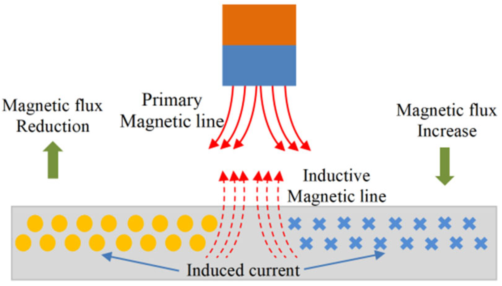
2.1. Measurement Principle and Calibration Method
2.2. High-Temperature Dynamic Experiment
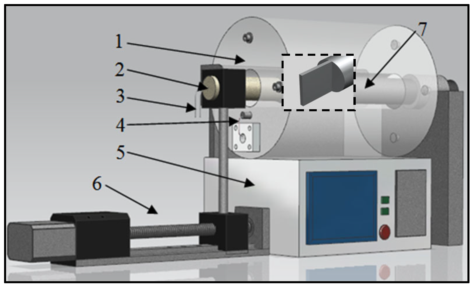
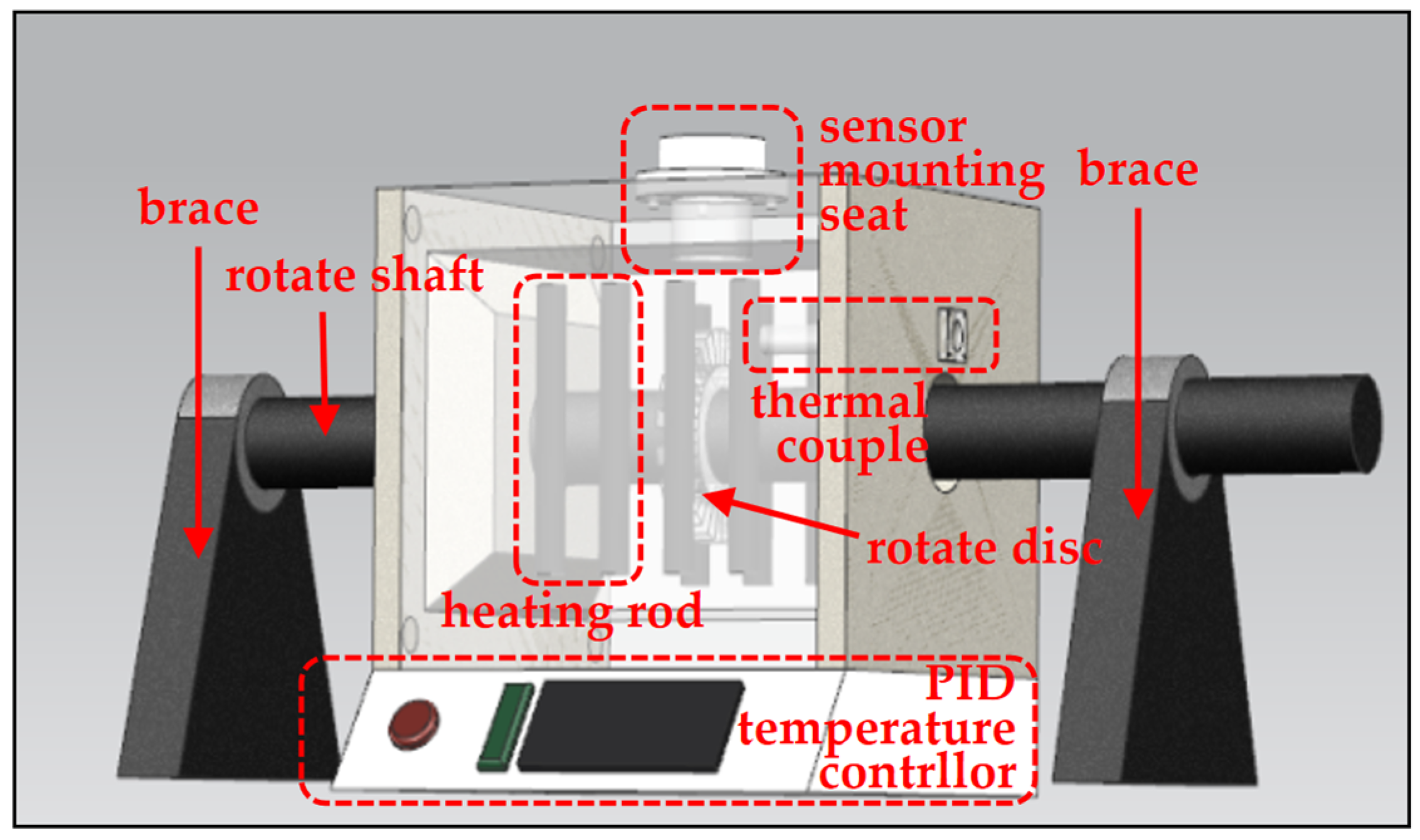
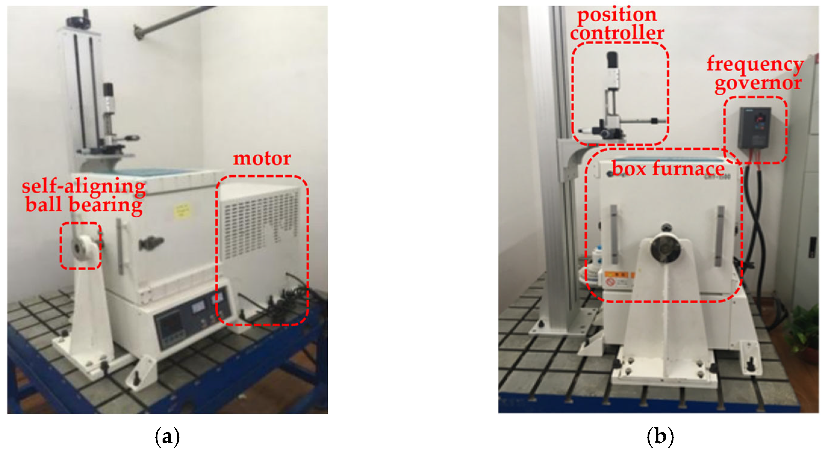
2.2.1. High-Temperature Mechanical System
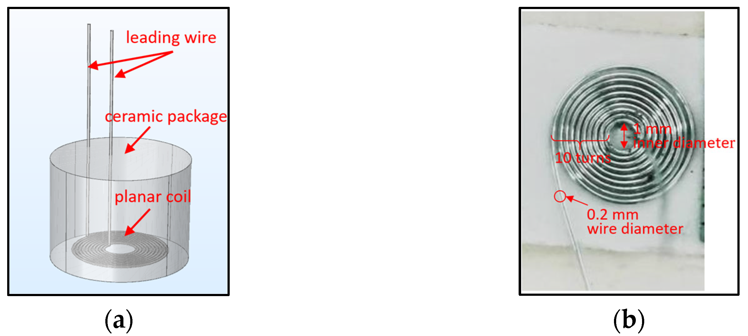
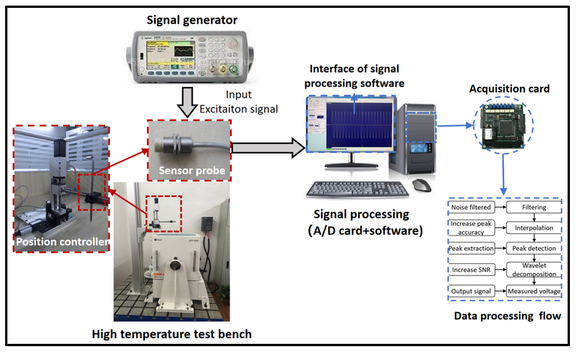
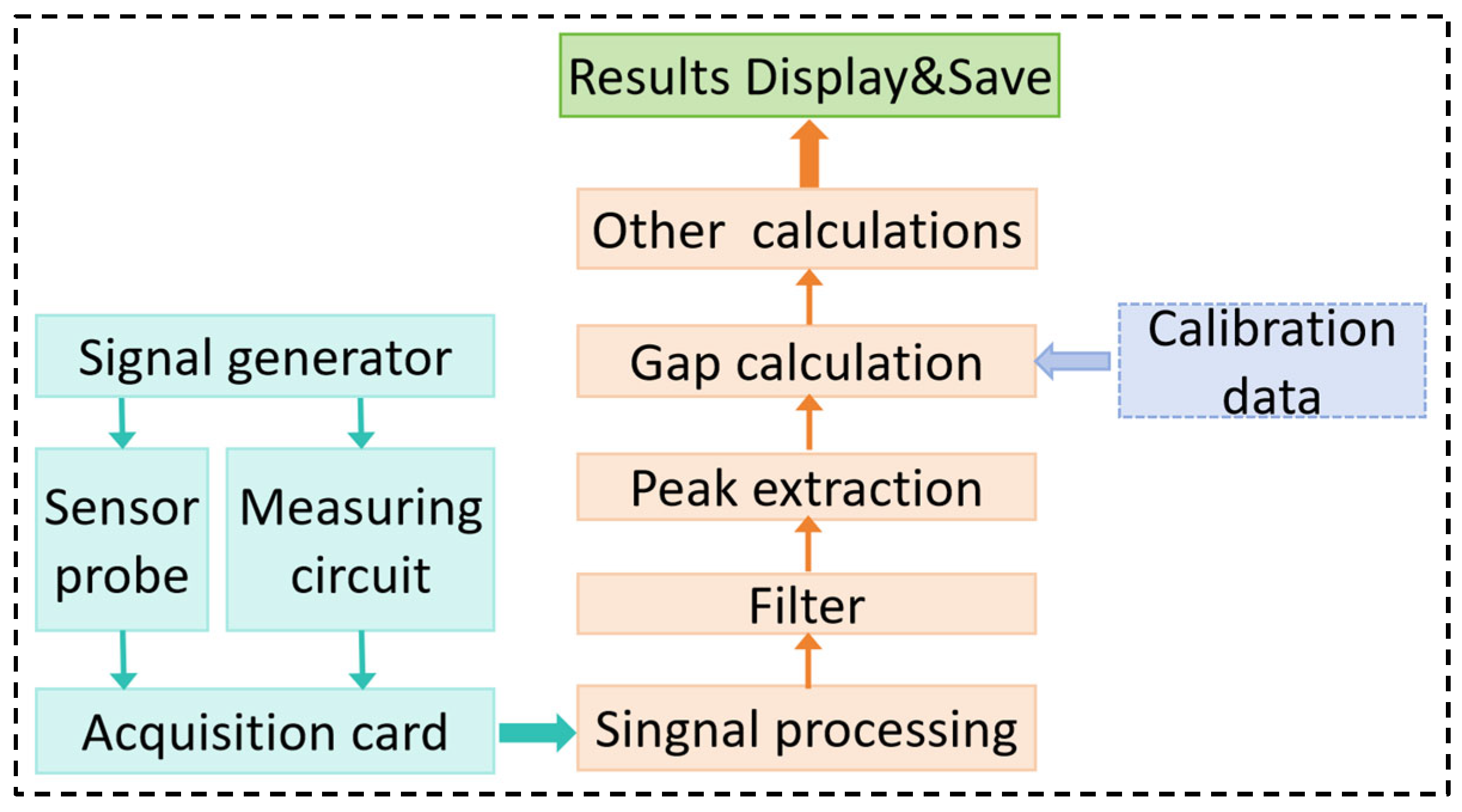
2.2.2. Sensing and Measurement System
2.2.3. High-Temperature Dynamic Experiment Conditions
3. Results
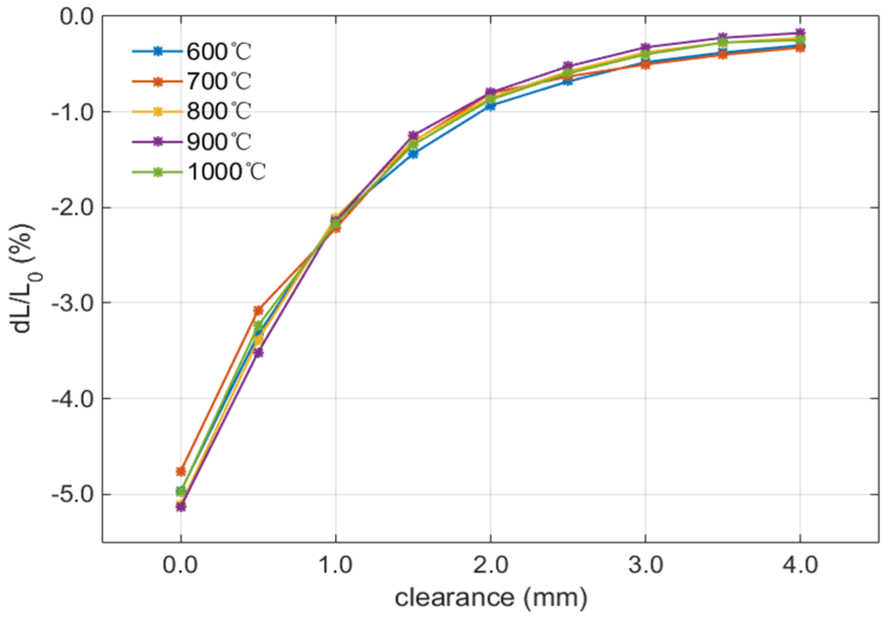
3.1. Dynamic Resolution Verification
3.2. Dynamic Measurement Results at Variable Conditions
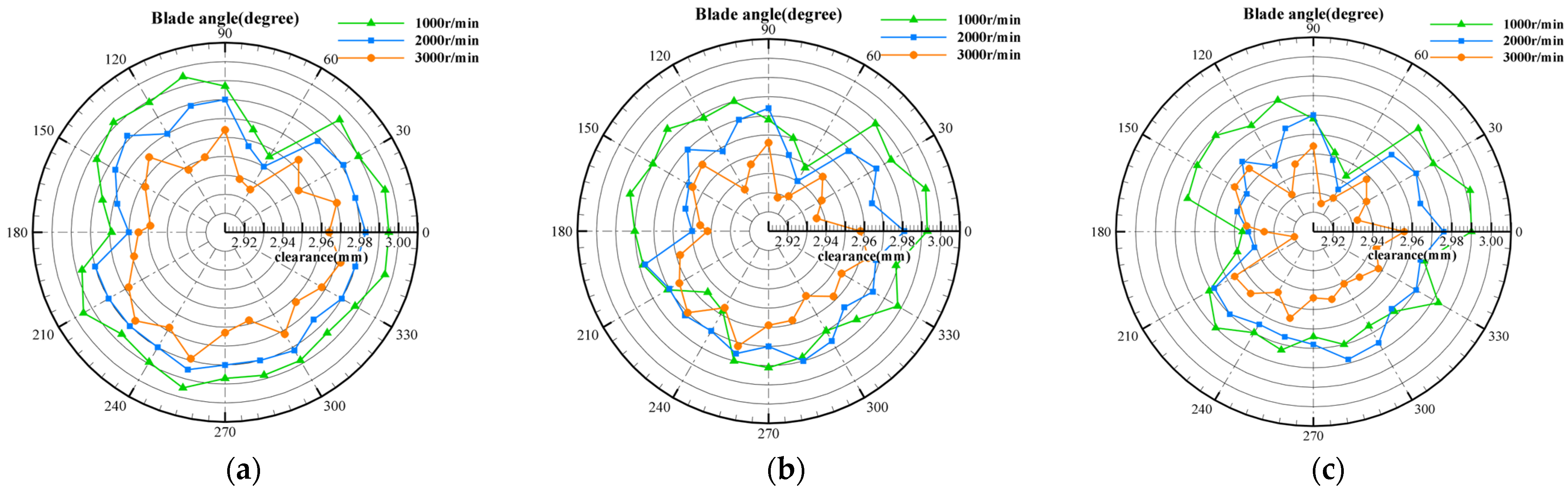
3.2.1. Dynamic Results at Variable Speed Conditions
- (1)
- The tip clearance varies significantly with the speed at different temperatures. The centrifugal load increases with the speed increasing, and the clearance value decreases obviously throughout the whole rotor.
- (2)
- Compared with Figure 11a–c, the thermal load increases as the temperature rises, and the clearance value decreases in the whole rotor.
3.2.2. Dynamic Results at Variable Temperature Conditions
- (1)
- The tip clearance varies significantly with temperature at different rotational speeds. The thermal load increases with the temperature rising, resulting in the increase in blade radial deformation and the decrease in blade tip clearance.
- (2)
- Comparing Figure 12a–c, the centrifugal load increases with the rotation speed increasing, resulting in an increase in blade radial deformation and a decrease in blade clearance.
4. Discussion
- (1)
- The inductive blade tip clearance measurement system has a good dynamic resolution. In a 1000 °C high-temperature environment, with a measurement range up to 3 mm and resolution up to 10 μm, it can detect the blade tip clearance variation under different speed and temperature conditions.
- (2)
- The dynamic clearance measurement results at a certain temperature and rotor speed, respectively, proved that the measuring system can distinguish the rotor radial deformation caused by the thermal load and centrifugal load, and the dynamic resolution is about 10 μm.
Author Contributions
Funding
Institutional Review Board Statement
Informed Consent Statement
Data Availability Statement
Conflicts of Interest
References
- Bunker, R. Axial turbine blade tips: Function, design, and durability. J. Propuls. Power 2006, 22, 271–285. [Google Scholar] [CrossRef]
- Xu, D.; Zhang, Q.; Hou, F. Change of high-pressure turbine clearance for an aeroengine and its effects. J. Shenyang Aerosp. Univ. 2022, 39, 24–28. [Google Scholar]
- Guo, Z.; Wei, Z.; Pan, P. Dynamic change of turbine blade tip clearance during engine ground starting. Eng. Test 2020, 60, 18–20. [Google Scholar]
- Niu, G.; Duan, F.; Zhou, Q.; Liu, Z.B. A dynamic measurement method of blade tip clearance based on microwave phase difference ranging. Acta Aeronaut. Astronaut. Sin. 2022, 43, 625396. [Google Scholar] [CrossRef]
- Abdul-Aziz, A.; Woike, M.R.; Anderson, R.C.; Aboumerhis, K. Propulsion on health monitoring assessed by microwave sensor performance and blade tip timing. In Smart Structure and NDE for Energy Systems and Industry 4.0; SPIE: Bellingham, WA, USA, 2019; Volume 10973. [Google Scholar]
- Vakhtin, A.; Chen, S.J.; Massick, S. Optical probe for monitoring blade tip clearance. In Proceedings of the 47th AIAA Aerospace Sciences Meeting Including the New Horizons Forum and Aerospace Exposition, Orlando, FL, USA, 5–8 January 2009; AIAA: Reston, VA, USA, 2009; p. 507. [Google Scholar]
- Hood Technology. Sensors. Available online: https://hoodtechbvm.com/sample-page/ (accessed on 5 May 2024).
- Wu, J.; Chen, Y.; Zhao, J.; Chen, J.; Guo, R. Dynamic synchronous measurement method of turbine blade speed and blade tip clearance based on laser self-mixing principle. Chin. J. Sci. Instrum. 2023, 44, 13–21. [Google Scholar] [CrossRef]
- Xue, Z.; Niu, G.; Yi, L.; Zheng, F.; Li, F.; Duan, F. Research on tip clearance measurement of shrouded turbine blades of turbofan engine. China Meas. Test 2023, 49, 16–22. [Google Scholar]
- Satish, T.N.; Vivek, A.; Anagha, S.N.; Rao, A.N.; Uma, G.; Umapathy, M.; Chandrasekhar, U.; Kiran, G. Novel resistor-capacitor network based capacitance signal conditioning circuit for tip clearance measurement on gas turbine engine. Proc. Inst. Mech. Eng. Part G J. Aerosp. Eng. 2020, 234, 342–360. [Google Scholar] [CrossRef]
- Duan, F.J.; Niu, G.Y.; Zhou, Q.; Fu, X.; Jiang, J. A review of online blade tip clearance measurement technologies for aeroengines. Acta Aeronaut. Astronaut. Sin. 2022, 43, 626014. [Google Scholar] [CrossRef]
- Fogale Turbo. Capablade Fusion with MC9225. Available online: http://www.fogale.fr/turbomachinery/index.php (accessed on 1 January 2023).
- Huang, C.; Hou, M. Technology for Measurement of Blade Tip Clearance in an Aeroengine. In Proceedings of the Aviation Test Technology Summit, Nanchang, China, 27–31 July 2008. [Google Scholar]
- Chana, K.S.; Cardwell, M.T.; Sullivan, J.S. The development of a hot section eddy current sensor for turbine tip clearance measurement. In Proceedings of the ASME Turbo Expo 2013: Turbine Technical Conference and Exposition, San Antonio, TX, USA, 3–7 June 2013. [Google Scholar]
- Sridhar, V.; Chana, K. Tip clearance measurements on an engine high pressure turbine using an eddy current sensor. In Proceedings of the ASME Turbo Expo 2017: Turbomachinery Technical Conference and Exposition, Charlotte, NC, USA, 26 June 2017. [Google Scholar]
- Du, L.; Zhu, X.; Zhe, J. A high sensitivity inductive sensor for blade tip clearance measurement. Smart Mater. Struct. 2014, 23, 065018. [Google Scholar] [CrossRef]
- Han, Y.; Zhong, C.; Zhu, X.; Zhe, J. Online monitoring of dynamic tip clearance of turbine blades in high temperature environment. Meas. Sci. Technol. 2018, 29, 045102. [Google Scholar] [CrossRef]
- Rokicki, E.; Przysowa, R.; Kotkowski, J. High temperature magnetic sensors for the hot section of aeroengines. Aerospace 2021, 8, 261. [Google Scholar] [CrossRef]
- Cui, D.; Liu, C.; Zhai, J. Optimal design of induction probe of high temperature eddy current sensor. Instrum. Technol. Sens. 2022, 1, 24–29. [Google Scholar]
- Borovik, S.; Sekisov, Y. Single-Coil Eddy Current Sensors and Their Application for Monitoring the Dangerous States of Gas-Turbine Engines. Sensors 2020, 20, 2107. [Google Scholar] [CrossRef] [PubMed]
- Borovik, S.; Kuteynikova, M.; Sekisov, Y. Reducing the Impact of Influence Factors on the Measurement Results from Single-Coil Eddy Current Sensors. Sensors 2023, 23, 351. [Google Scholar] [CrossRef] [PubMed]
- Yang, Q.; Li, L.; Zhao, Y.; Shu, P. Experimental measurement of axial clearance in scroll compressor using eddy current displacement sensor. Proc. Inst. Mech. Eng. 2008 Part C J. Mech. Eng. Sci. 2008, 222, 1315–1320. [Google Scholar] [CrossRef]
- Li, H.; Ren, Z.; Chen, R.; Yu, W. Influence of structural parameters on the static performance of self-inductive radial displacement sensor. Meas. Sci. Technol. 2022, 33, 125106. [Google Scholar] [CrossRef]
- Wang, W.; Shao, H.; Shao, X.; Song, K. Investigation on the turbine blade tip clearance measurement and active clearance control based on eddy current pulse trigger method. In Proceedings of the ASME Turbo Expo 2017: Turbomachinery Technical Conference and Exposition, Charlotte, NC, USA, 26 June 2017. [Google Scholar]
- Ye, D.; Duan, F.; Zhou, Q.; Cheng, Z.; Li, X.; Niu, G. Vibrations measurements for shrouded blades of steam turbines based on eddy current sensors with high frequency response. J. Meas. Sci. Instrum. 2019, 10, 315–321. [Google Scholar] [CrossRef]
- Zhao, L.; Liu, F.; Lyu, Y.; Liu, Z.; Zhao, Z. Numerical investigationon the infuence of turbine rotor parameters on the eddy current sensor for the dynamic blade tip clearance measurement. Sensors 2024, 24, 5938. [Google Scholar] [CrossRef]
- Sillanpää, T.; Smirnov, A.; Jaatinen, P.; Vuojolainen, J.; Nevaranta, N.; Jastrzebski, R.; Pyrhönen, O. Three-Axis Inductive Displacement Sensor Using Phase-Sensitive Digital Signal Processing for Industrial Magnetic Bearing Applications. Actuators 2021, 10, 115. [Google Scholar] [CrossRef]
- Liu, Z.; Zhao, Z.; Lyu, Y.; Zhao, L. Experimental investigation of inductive sensor characteristic for blade tip clearance measurement at high temperature. Sensors 2019, 19, 3694. [Google Scholar] [CrossRef] [PubMed]


| Performance | Discharge Probe Method | Optic Fiber Method | Capacitive Method | Inductive Method | Microwave Method |
|---|---|---|---|---|---|
| Temperature, °C | 1500 | 1100 | 1400 | 1400 | 1200 |
| Precision, μm | 25 | 10 | 15 | 10 | 25 |
| Range, mm | 6 | 10 | 3 | 5 | 6 |
| Rotate speed, r/min | 8000 | 60,000 | 30,000 | 10,000 | 18,000 |
| Advantage | High-temperature resistance; not affected by the top surface structure | High precision; compact structure | High-temperature resistance and pressure-resistant; corrosion resistance | Anti-pollution; measuring outside the case | High-temperature resistance and pressure-resistant; corrosion resistance |
| Disadvantage | Minimum clearance only | Easily contaminated | Influenced by the environment | Large probe structure | High product cost |
| Material | Melting Point/°C | Coefficient of Thermal Expansion/(10−6/°C) | Other Characteristics |
|---|---|---|---|
| Inconel600 | 1370–1425 | 15.7 | High strength at 650 °C; highest operating temperature in the air is 1175 °C. |
| Inconel625 | 1290–1350 | 16.6 | Good tensile properties and fatigue properties below 980 °C. |
| Inconel718 | 1210–1344 | 16.2 | Easy processing; high tensile strength and fatigue strength at 700 °C; high oxidation resistance at 1000 °C. |
| Inconel750 | 1396–1430 | 15.8 | Good corrosion resistance and oxidation resistance below 980 °C. |
| Parameter | Limited Temperature | Heating Rate | Control Accuracy | Temperature Distribution Difference in Section |
|---|---|---|---|---|
| Value | 1500 °C | <20 °C/min | ≤±2 °C | ≤±3 °C |
| Parameter | Value |
|---|---|
| Rotating speed, r/min | 1000–15,000 |
| Driving power, kW | 10 |
| Heating temperature, °C | room temperature ~1500 |
| Heating rate, °C/min | ≤20 |
| Heating control accuracy, °C | ≤±2 |
| Furnace chamber size, mm | 120 × 120 × 120 |
| Sampling frequency, MHz | 0.1–100 |
| Sampling channel | 4 channels |
| Atmosphere | high temperature and oxidation |
| Validation Performance | Experiment Operating Parameters | |||
|---|---|---|---|---|
| Dynamic resolution | Temperature, °C | Rotate speed, r/min | ||
| 1000 | 3000 | |||
| Dynamic response | Temperature, °C | Rotate speed, r/min | ||
| 600–1000 | 1000 | 2000 | 3000 | |
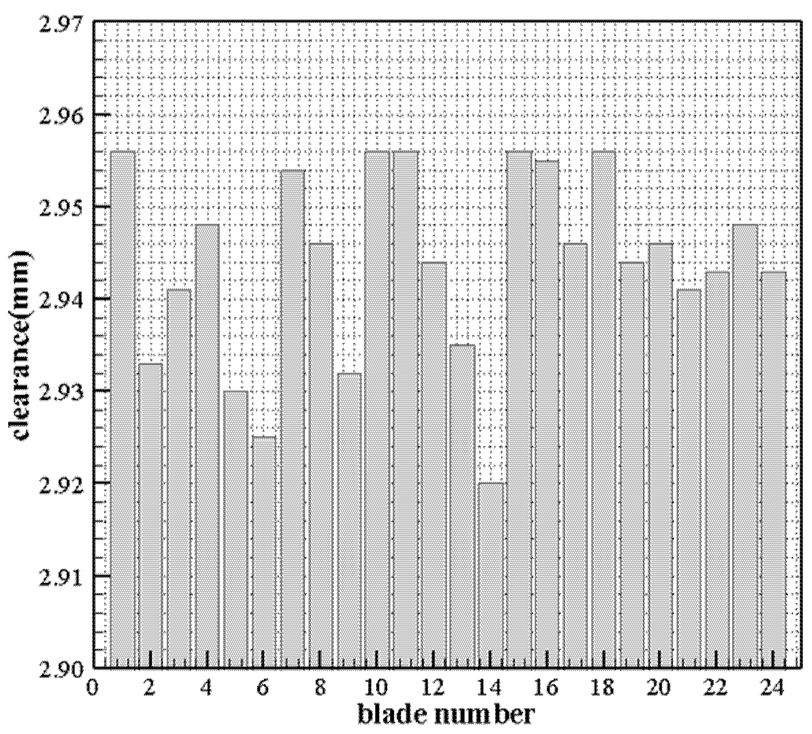
| Blade No. | Clearance (mm) | Blade No. | Clearance (mm) | Blade No. | Clearance (mm) |
|---|---|---|---|---|---|
| 1 | 2.956 | 9 | 2.932 | 17 | 2.946 |
| 2 | 2.933 | 10 | 2.956 | 18 | 2.956 |
| 3 | 2.941 | 11 | 2.956 | 19 | 2.944 |
| 4 | 2.948 | 12 | 2.944 | 20 | 2.946 |
| 5 | 2.930 | 13 | 2.935 | 21 | 2.941 |
| 6 | 2.925 | 14 | 2.920 | 22 | 2.943 |
| 7 | 2.954 | 15 | 2.956 | 23 | 2.948 |
| 8 | 2.946 | 16 | 2.955 | 24 | 2.943 |
| Temperature, °C | Rotate Speed, r/min | Max. | Min. | Avg. | Range |
|---|---|---|---|---|---|
| 600 | 1000 | 2.996 | 2.956 | 2.987 | 0.040 |
| 2000 | 2.985 | 2.950 | 2.976 | 0.035 | |
| 3000 | 2.979 | 2.936 | 2.961 | 0.043 | |
| 800 | 1000 | 2.995 | 2.948 | 2.977 | 0.047 |
| 2000 | 2.981 | 2.940 | 2.967 | 0.041 | |
| 3000 | 2.972 | 2.928 | 2.952 | 0.044 | |
| 1000 | 1000 | 2.992 | 2.943 | 2.971 | 0.049 |
| 2000 | 2.978 | 2.935 | 2.962 | 0.043 | |
| 3000 | 2.956 | 2.920 | 2.944 | 0.036 |
| Rotate Speed, r/min | Temperature, °C | Max. | Min. | Avg. | Range |
|---|---|---|---|---|---|
| 1000 | 600 | 2.996 | 2.956 | 2.987 | 0.040 |
| 700 | 2.995 | 2.950 | 2.979 | 0.045 | |
| 800 | 2.995 | 2.948 | 2.977 | 0.047 | |
| 900 | 2.992 | 2.945 | 2.974 | 0.047 | |
| 1000 | 2.992 | 2.943 | 2.971 | 0.049 | |
| 2000 | 600 | 2.985 | 2.950 | 2.976 | 0.035 |
| 700 | 2.983 | 2.945 | 2.972 | 0.038 | |
| 800 | 2.981 | 2.940 | 2.967 | 0.041 | |
| 900 | 2.978 | 2.938 | 2.963 | 0.040 | |
| 1000 | 2.978 | 2.935 | 2.962 | 0.043 | |
| 3000 | 600 | 2.979 | 2.936 | 2.961 | 0.043 |
| 700 | 2.976 | 2.920 | 2.955 | 0.056 | |
| 800 | 2.972 | 2.928 | 2.952 | 0.044 | |
| 900 | 2.958 | 2.925 | 2.946 | 0.038 | |
| 1000 | 2.956 | 2.920 | 2.944 | 0.036 |
Disclaimer/Publisher’s Note: The statements, opinions and data contained in all publications are solely those of the individual author(s) and contributor(s) and not of MDPI and/or the editor(s). MDPI and/or the editor(s) disclaim responsibility for any injury to people or property resulting from any ideas, methods, instructions or products referred to in the content. |
© 2025 by the authors. Licensee MDPI, Basel, Switzerland. This article is an open access article distributed under the terms and conditions of the Creative Commons Attribution (CC BY) license (https://creativecommons.org/licenses/by/4.0/).
Share and Cite
Zhao, Z.; Zhao, L.; Lyu, Y.; Liu, Z. Experimental Verification of High-Temperature Resistance and High Resolution of Inductive Tip Clearance Measurement System. Sensors 2025, 25, 3145. https://doi.org/10.3390/s25103145
Zhao Z, Zhao L, Lyu Y, Liu Z. Experimental Verification of High-Temperature Resistance and High Resolution of Inductive Tip Clearance Measurement System. Sensors. 2025; 25(10):3145. https://doi.org/10.3390/s25103145
Chicago/Turabian StyleZhao, Ziyu, Lingqiang Zhao, Yaguo Lyu, and Zhenxia Liu. 2025. "Experimental Verification of High-Temperature Resistance and High Resolution of Inductive Tip Clearance Measurement System" Sensors 25, no. 10: 3145. https://doi.org/10.3390/s25103145
APA StyleZhao, Z., Zhao, L., Lyu, Y., & Liu, Z. (2025). Experimental Verification of High-Temperature Resistance and High Resolution of Inductive Tip Clearance Measurement System. Sensors, 25(10), 3145. https://doi.org/10.3390/s25103145