
Obstacle-Avoidance Planning in C-Space for Continuum Manipulator Based on IRRT-Connect


Abstract
1. Introduction
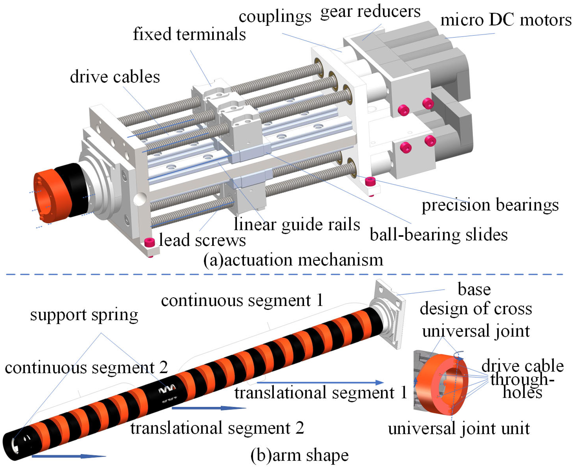
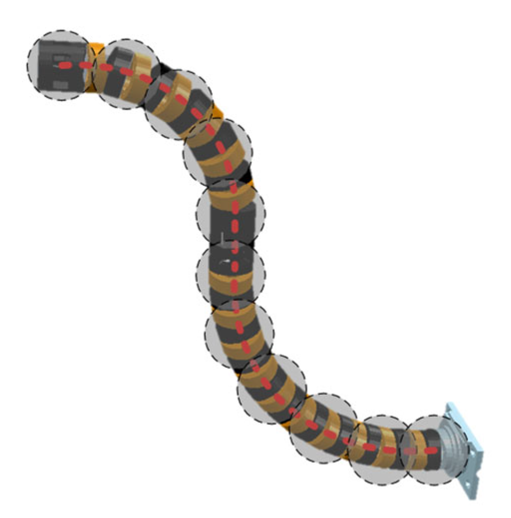
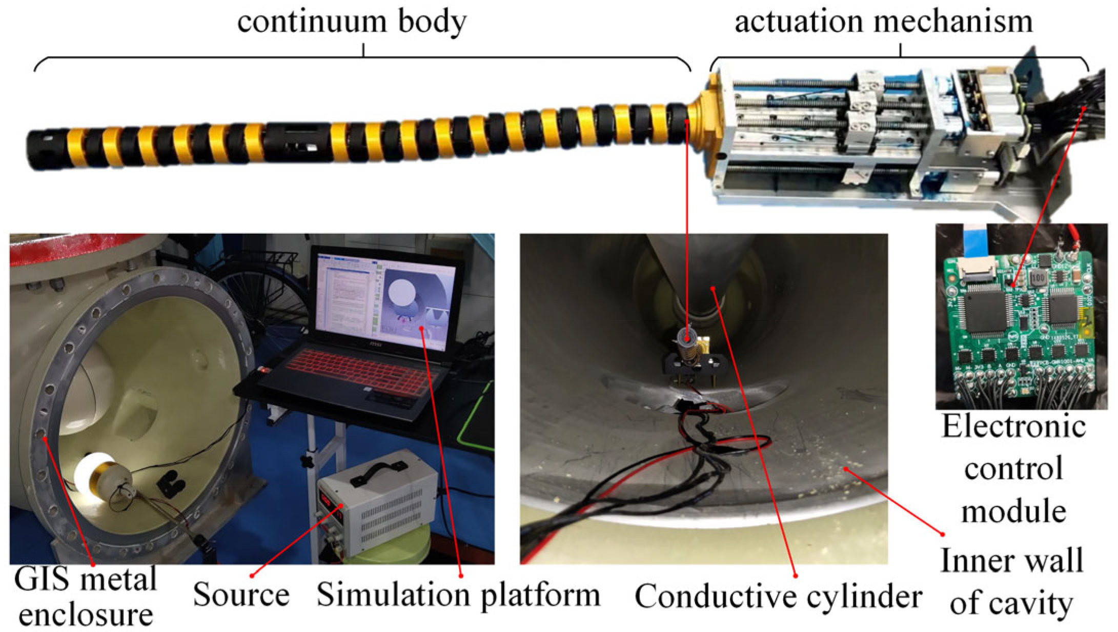
2. Machine Design
3. Problem Description and Kinematics Analysis
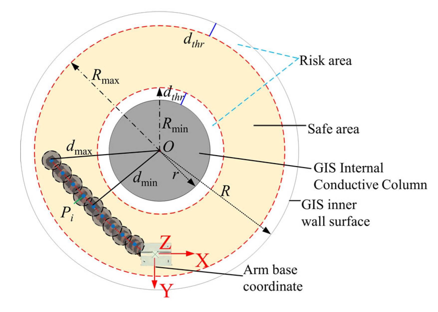
3.1. Problem Description
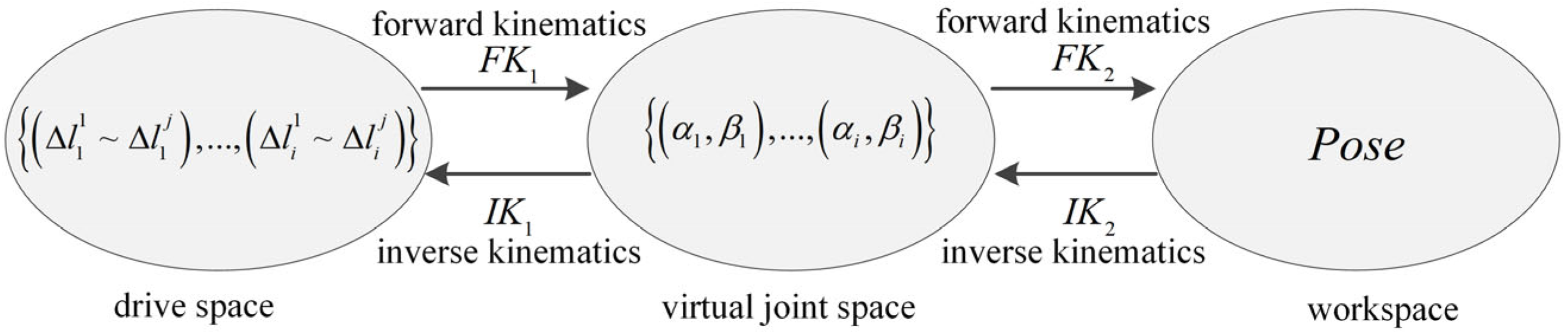
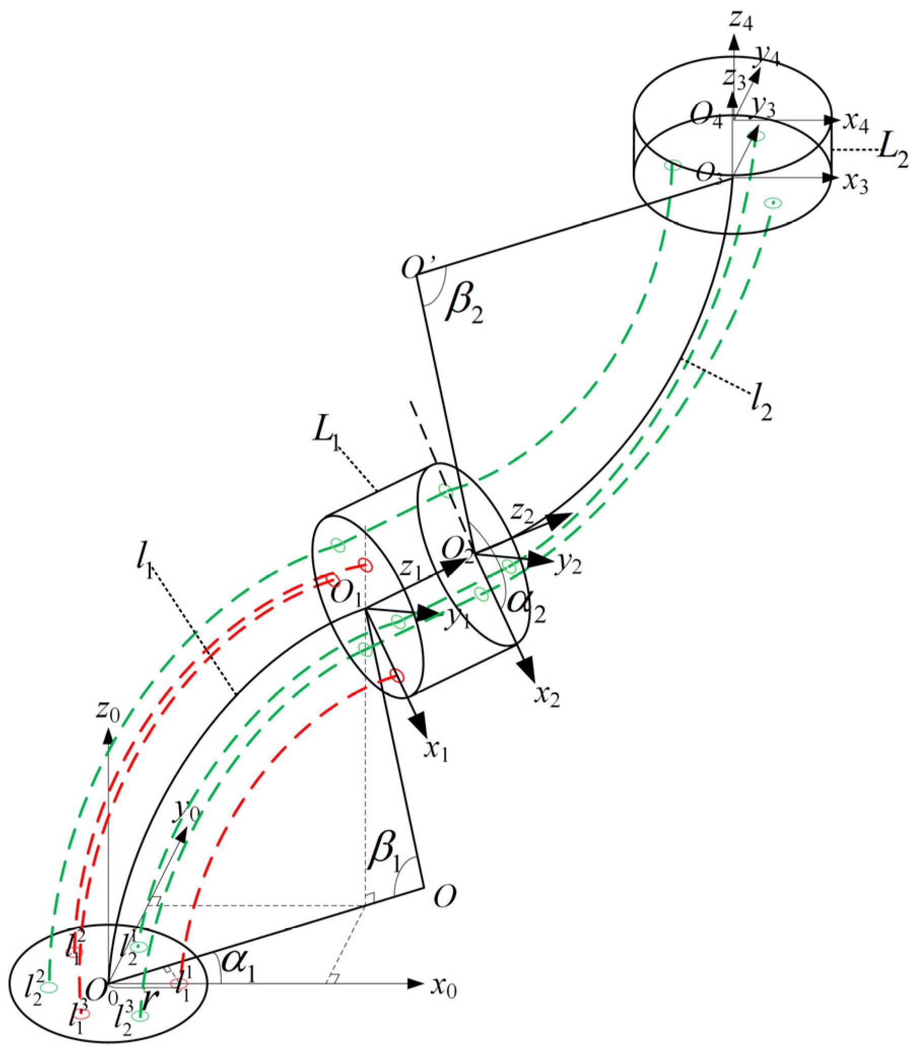
3.2. Kinematics Analysis of Continuum Manipulators
4. Inverse Kinematics Solving Based on IRRT-Connect
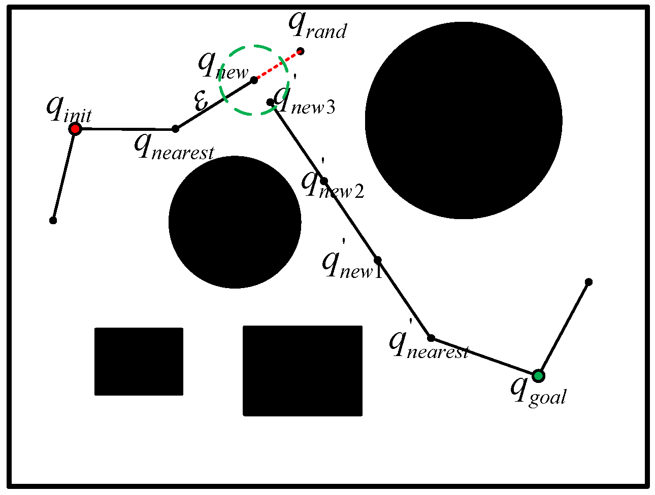
4.1. Algorithm Theory
4.2. Step Optimization
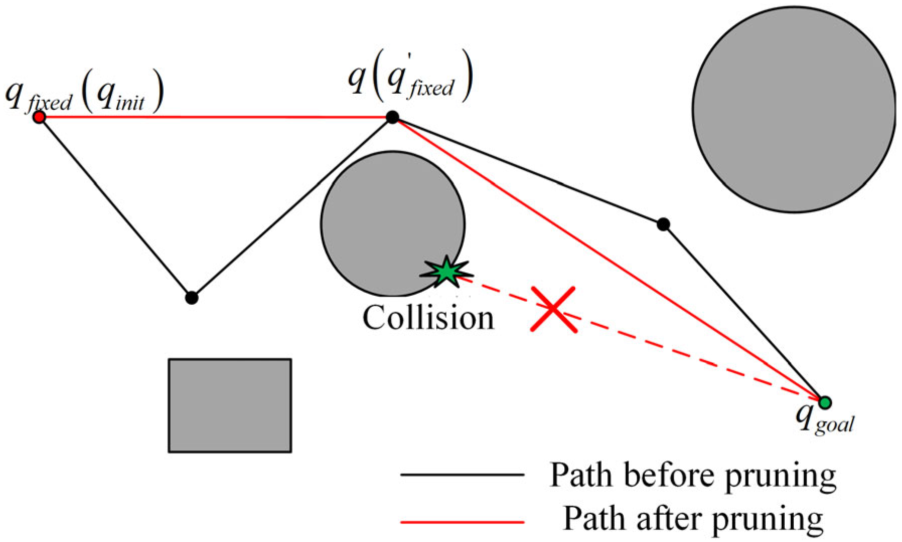
4.3. Pruning Strategy
4.4. Collision Detection
4.5. Trajectory Planning Based on Driving Space
5. Simulation Results and Analysis
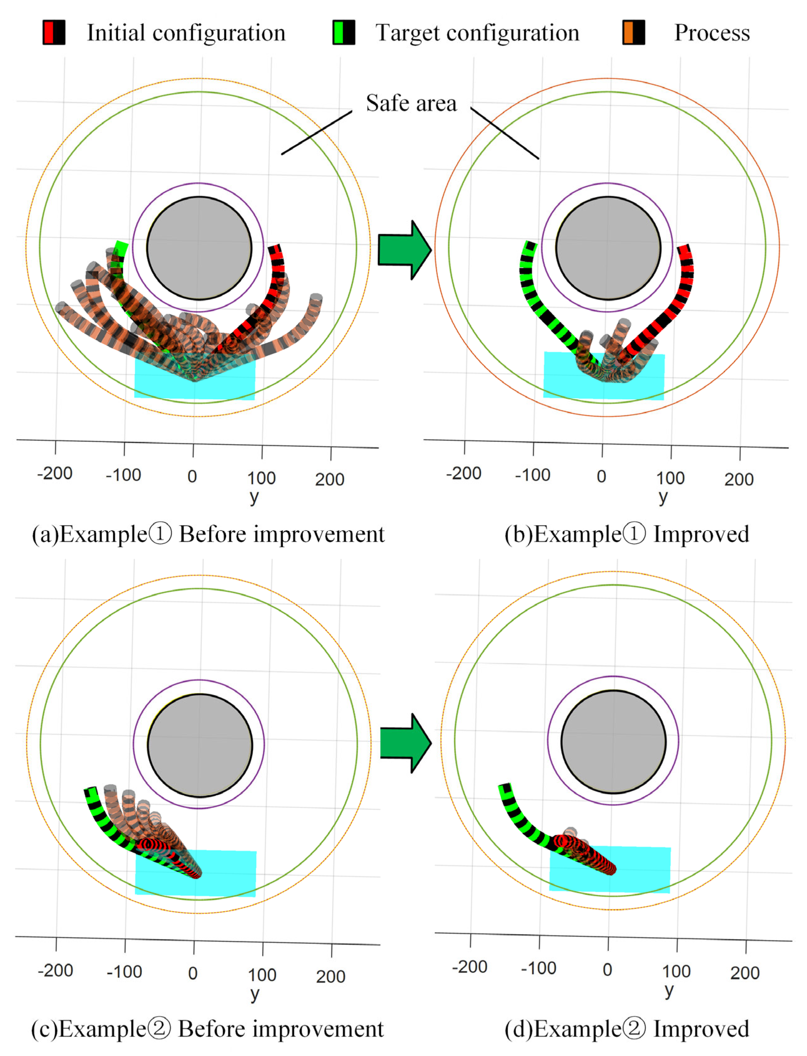
5.1. IRRT-Connect Algorithm Simulation
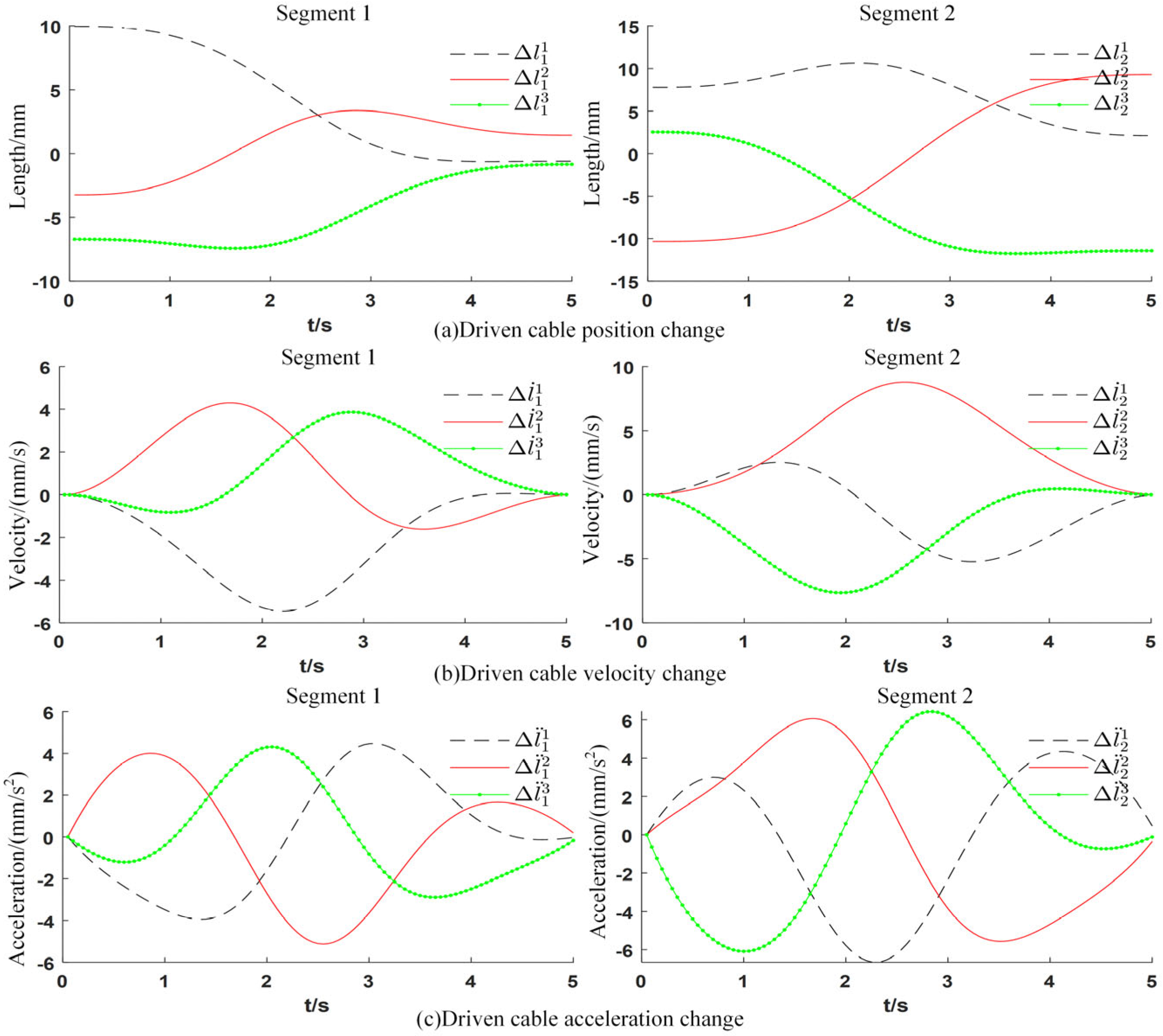
5.2. Drive Trajectory Smoothing Test
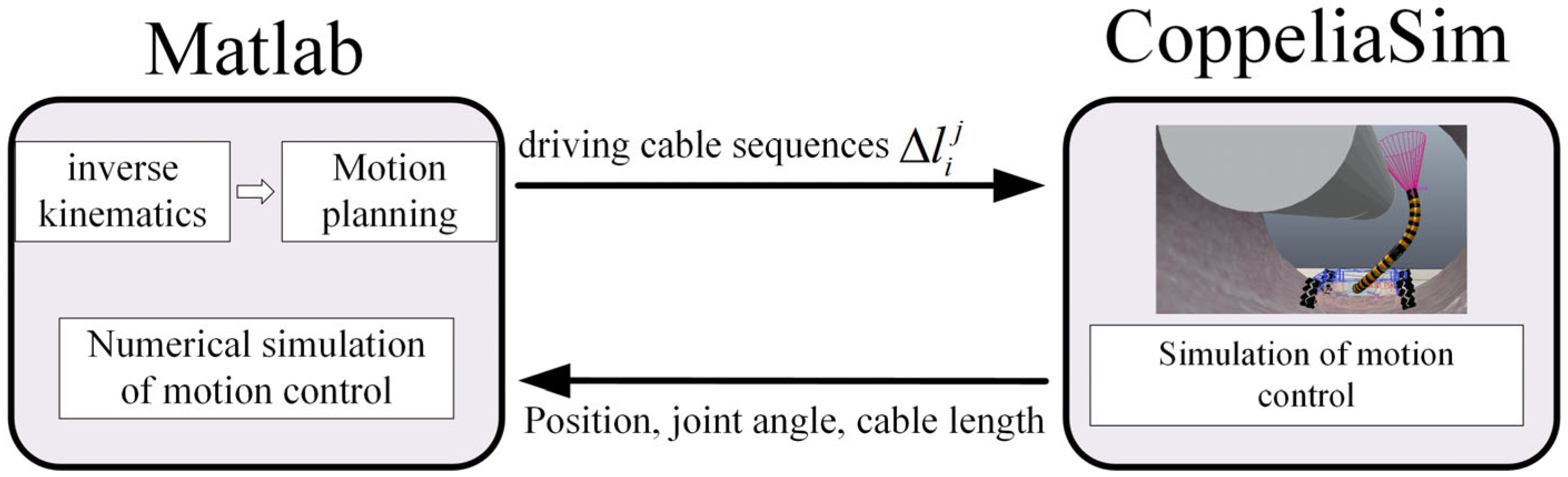
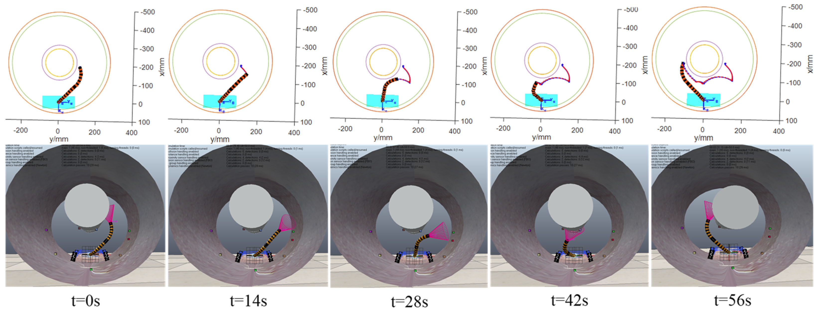
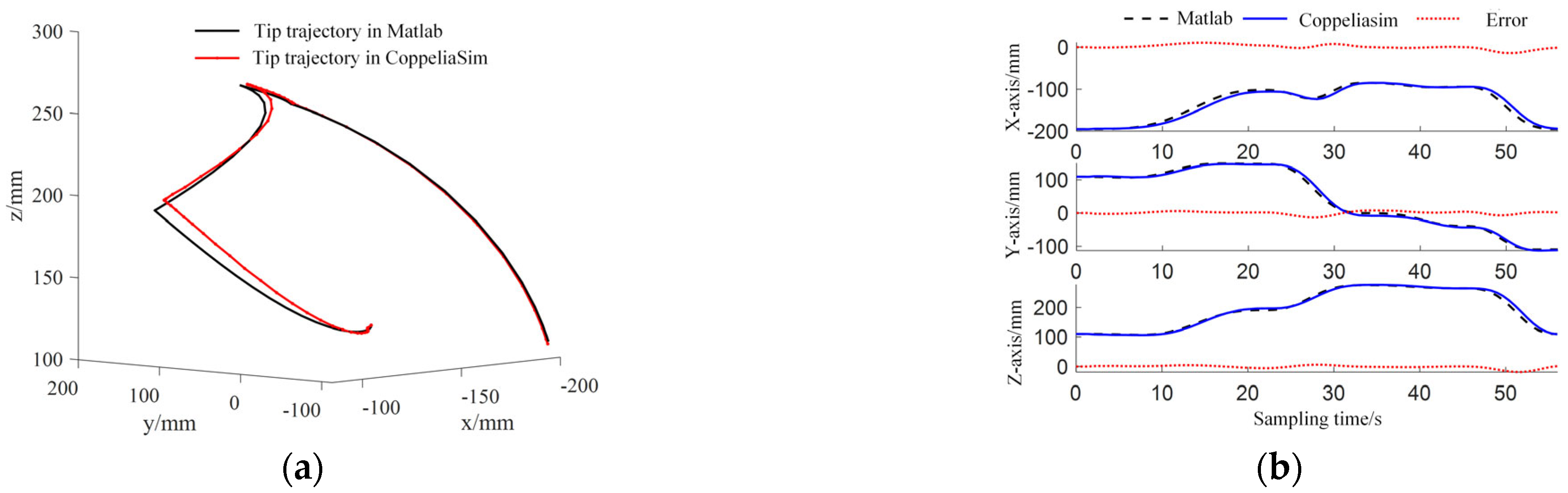
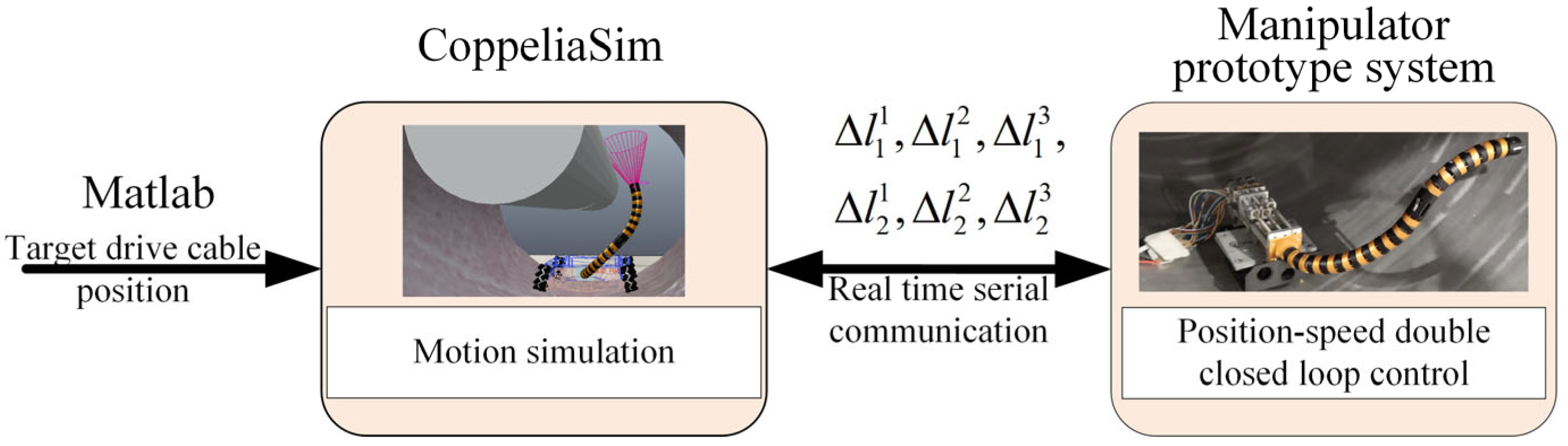
5.3. Co-Simulation of MATLAB and CopeliaSim
6. Experiment and Result Analysis
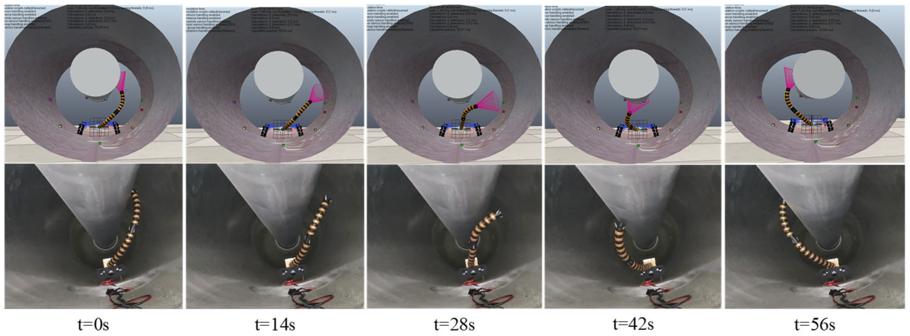
6.1. Experiment Preparation and Process
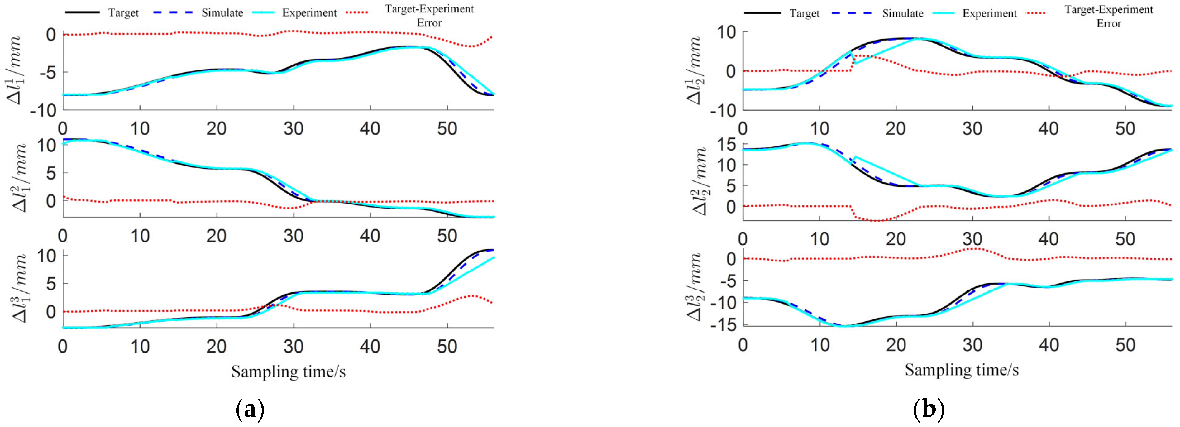
6.2. Analysis of Experimental Results
7. Conclusions
Author Contributions
Funding
Institutional Review Board Statement
Informed Consent Statement
Data Availability Statement
Conflicts of Interest
Abbreviations
| IRRT | Improved rapidly exploring random tree |
| GIS | gas-insulated switchgear |
| C-space | configuration space |
| PRM | probabilistic roadmap |
References
- The National Energy Administration. Releases 2022 National Power Industry Statistics [EB/OL]. 18 January 2023. Available online: https://www.nea.gov.cn/2023-01/18/c_1310691509.htm (accessed on 18 February 2024).
- IEA. Electricity Market Report 2023 [EB/OL]. 16 February 2023. Available online: https://www.iea.org/reports/electricity-market-report-2023 (accessed on 18 February 2024).
- Kolachalama, S.; Lakshmanan, S. Continuum Robots for Manipulation Applications: A Survey. J. Robot. 2020, 2020, 4187048. [Google Scholar] [CrossRef]
- Luo, M.; Li, E.; Zhang, A.; Tan, M.; Liang, Z. A Bioinspired Coiled Cable-Driven Manipulator: Mechatronic Design and Kinematics Planning with Multiconstraints. IEEE Trans. Mechatron. 2023, 28, 3155–3166. [Google Scholar] [CrossRef]
- Ma, C.; Zhao, T.; Xiang, G.; Ren, J.; Chen, Y.; Dian, S. End Positioning Control of Flexible Manipulator Based on Inverse Kinematics. J. Mech. Eng. 2021, 57, 163–171. [Google Scholar]
- Li, J.; Hu, Y.; Yang, S. A Novel Knowledge-Based Genetic Algorithm for Robot Path Planning in Complex Environments. IEEE Trans. Evol. Comput. 2025, 29, 375–389. [Google Scholar] [CrossRef]
- Hu, K.; Dong, Q.; Ma, Z.; Li, B.; Qi, T. Welding robot path planning based on ant colony algorithm. In Proceedings of the 2024 5th International Conference on Artificial Intelligence and Electromechanical Automation (AIEA), Shenzhen, China, 14–16 June 2024; pp. 13–18. [Google Scholar]
- Wang, L.; Sun, Z.; Wang, Y.; Wang, J.; Zhao, Z.; Yang, C.; Yan, C. A Pre-Grasping Motion Planning Method Based on Improved Artificial Potential Field for Continuum Robots. Sensors 2023, 23, 9105. [Google Scholar] [CrossRef] [PubMed]
- Mayer, A.; Müller, D.; Raisch, A. Demonstration-based programming of multi-point trajectories for collaborative continuum robots. IFAC-PapersOnLine 2019, 52, 513–518. [Google Scholar] [CrossRef]
- Greigarn, T.; Poirot, N.; Xu, X. Jacobian-based task-space motion planning for MRI-actuated continuum robots. IEEE Robot. Autom. Lett. 2018, 4, 145–152. [Google Scholar] [CrossRef] [PubMed]
- Graule, M.; McCarthy, T.; Teeple, C.; Werfel, J.; Wood, R. SoMoGym: A toolkit for developing and evaluating controllers and reinforcement learning algorithms for soft robots. IEEE Robot. Autom. Lett. 2022, 7, 4071–4078. [Google Scholar] [CrossRef]
- Fu, J.; Sun, G.; Liu, J.; Yao, W.; Wu, L. On hierarchical multi-UAV dubins traveling salesman problem paths in a complex obstacle environment. IEEE Trans. Cybern. 2023, 54, 123–135. [Google Scholar] [CrossRef] [PubMed]
- Fu, J.; Yao, W.; Sun, G.; Ma, Z.; Dong, B.; Ding, J.; Wu, L. Multirobot cooperative path optimization approach for multi-objective coverage in a congestion risk environment. IEEE Trans. Syst. Man Cybern. Syst. 2023, 54, 1816–1827. [Google Scholar] [CrossRef]
- Kavraki, L.; Kolountzakis, M.; Latombe, J. Analysis of probabilistic roadmaps for path planning. IEEE Trans. Robot. Autom. 1998, 14, 166–171. [Google Scholar] [CrossRef]
- Véras, L.; Medeiros, F.; Guimaráes, L. Systematic literature review of sampling process in rapidly-exploring random trees. IEEE Access 2019, 7, 50933–50953. [Google Scholar] [CrossRef]
- Chiluisa, A.; Van Rossum, F.; Gafford, J. Computational optimization of notch spacing for a transnasal ear endoscopy continuum robot. In Proceedings of the 2020 International Symposium on Medical Robotics, Atlanta, GA, USA, 18–20 November 2020; pp. 188–194. [Google Scholar]
- Wu, K.; Wu, L.; Ren, H. Motion planning of continuum tubular robots based on centerlines extracted from statistical atlas. In Proceedings of the 2015 IEEE/RSJ International Conference on Intelligent Robots and Systems, Hamburg, Germany, 28 September–2 October 2015; pp. 5512–5517. [Google Scholar]
- Qi, R.; Zhou, W.; Wang, T. An Obstacle Avoidance Trajectory Planning Scheme for Space Manipulators Based on Genetic Algorithm. ROBOT 2014, 36, 263–270. [Google Scholar]

| RRT-Connect Planner for Continuum Manipulator (xinit, xgoal, Map) | |
|---|---|
| 1 | Ta.init(xinit);Tb.init(xgoal); |
| 2 | for k = 1 to K do |
| 3 | xrand←SampleNode(Step Optimization): |
| 4 | if not(Extend(Ta, xrand)) = Trapped then |
| 5 | if (Connect(Tb, xnew)) = Reached then |
| 6 | Return PATH(Ta, Tb); |
| 7 | end if |
| 8 | end if |
| 9 | then |
| 10 | SwapTrees(Ta, Tb); |
| 11 | end if |
| 12 | end for |
| 13 | PathPruning() |
| 14 | Return Failure |
| Example | Algorithm | Average Number of Iterations | Average Number of Leaf Nodes | Average Number of Path Nodes | Average Number of Path Nodes |
| ➀ | RRT-Connect | 150 | 46 | 19 | 0.017 s |
| IRRT-Connect | 48 | 12 | 8 | 0.011 s | |
| ➁ | RRT-Connect | 2 | 8 | 8 | 0.002 s |
| IRRT-Connect | 5 | 5 | 4 | 0.002 s |
Disclaimer/Publisher’s Note: The statements, opinions and data contained in all publications are solely those of the individual author(s) and contributor(s) and not of MDPI and/or the editor(s). MDPI and/or the editor(s) disclaim responsibility for any injury to people or property resulting from any ideas, methods, instructions or products referred to in the content. |
© 2025 by the authors. Licensee MDPI, Basel, Switzerland. This article is an open access article distributed under the terms and conditions of the Creative Commons Attribution (CC BY) license (https://creativecommons.org/licenses/by/4.0/).
Share and Cite
Lang, Y.; Liu, J.; Xiao, Q.; Tang, J.; Chen, Y.; Dian, S. Obstacle-Avoidance Planning in C-Space for Continuum Manipulator Based on IRRT-Connect. Sensors 2025, 25, 3081. https://doi.org/10.3390/s25103081
Lang Y, Liu J, Xiao Q, Tang J, Chen Y, Dian S. Obstacle-Avoidance Planning in C-Space for Continuum Manipulator Based on IRRT-Connect. Sensors. 2025; 25(10):3081. https://doi.org/10.3390/s25103081
Chicago/Turabian StyleLang, Yexing, Jiaxin Liu, Quan Xiao, Jianeng Tang, Yuanke Chen, and Songyi Dian. 2025. "Obstacle-Avoidance Planning in C-Space for Continuum Manipulator Based on IRRT-Connect" Sensors 25, no. 10: 3081. https://doi.org/10.3390/s25103081
APA StyleLang, Y., Liu, J., Xiao, Q., Tang, J., Chen, Y., & Dian, S. (2025). Obstacle-Avoidance Planning in C-Space for Continuum Manipulator Based on IRRT-Connect. Sensors, 25(10), 3081. https://doi.org/10.3390/s25103081