
Design and Implementation of C-Band Large-Power Planar Butler Matrix in SRS


Abstract
1. Introduction
2. Principle and Design Method
2.1. Principle
2.2. Square Coaxial Line
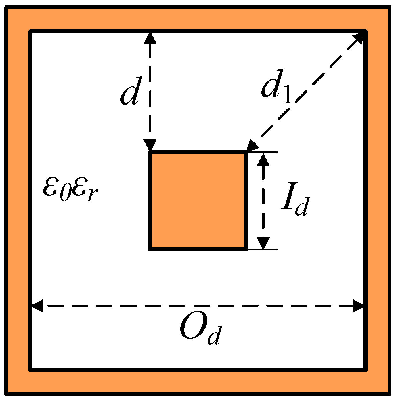
2.2.1. Design of Square Coaxial Line
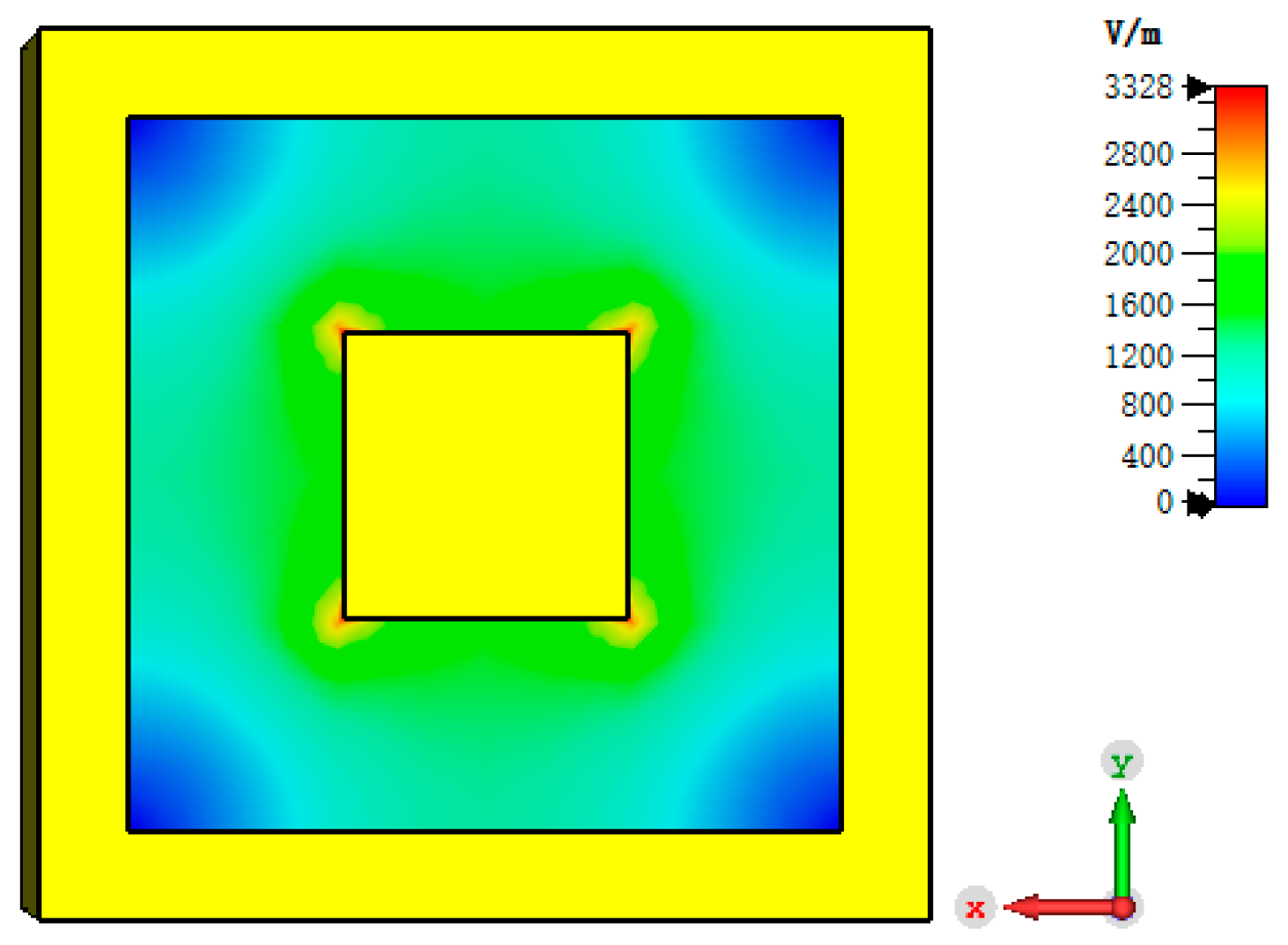
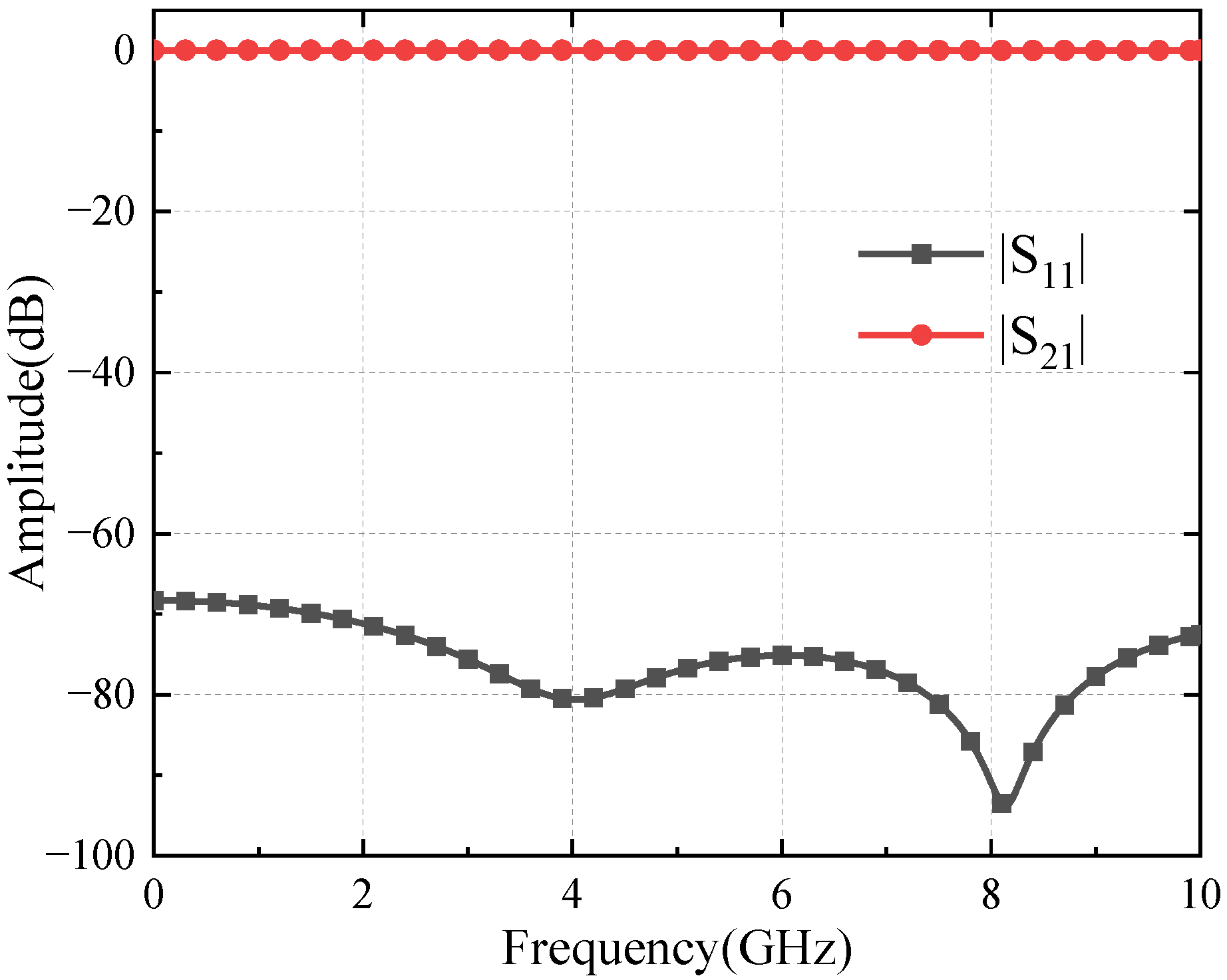
2.2.2. Electrical Performance Simulation
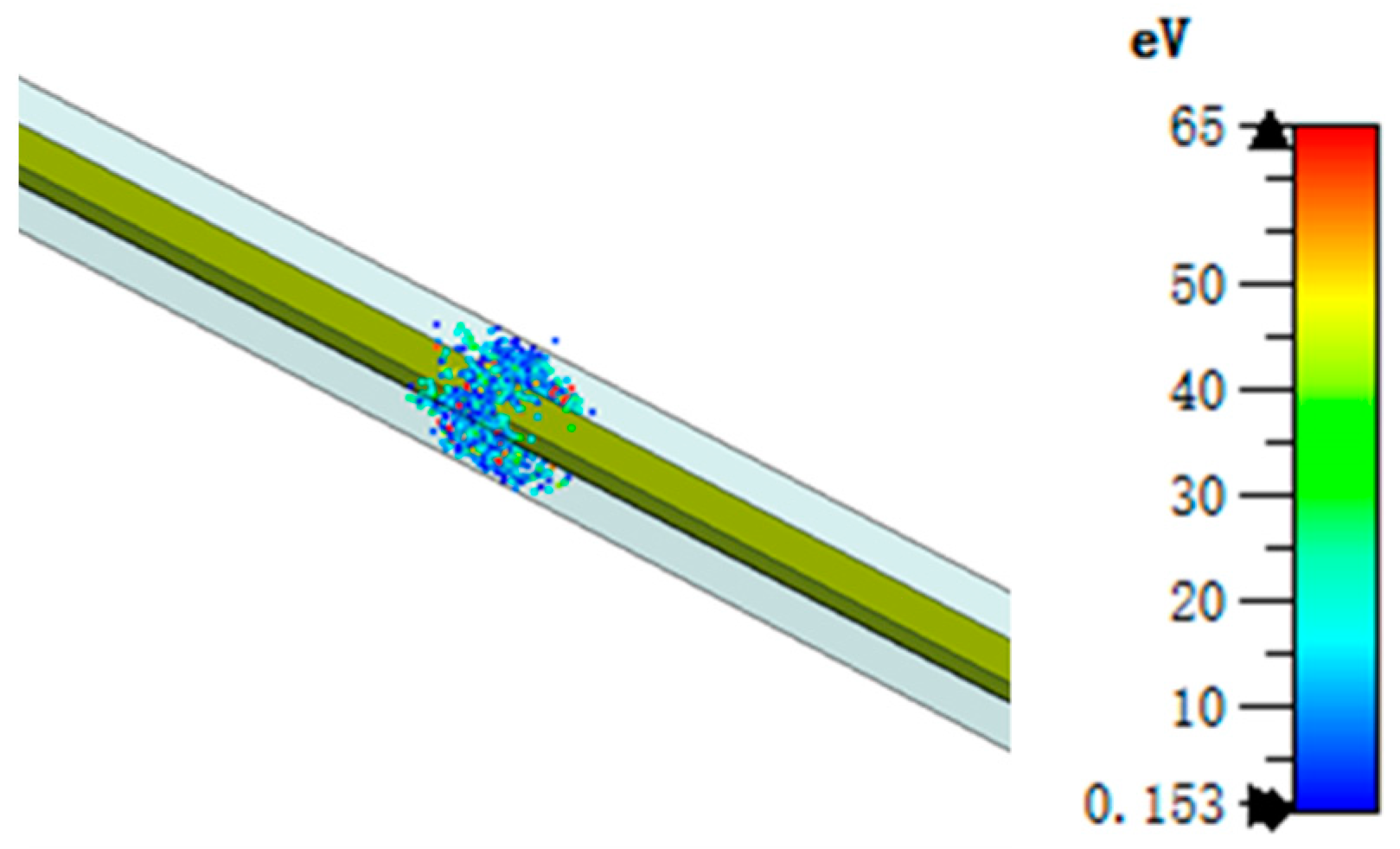
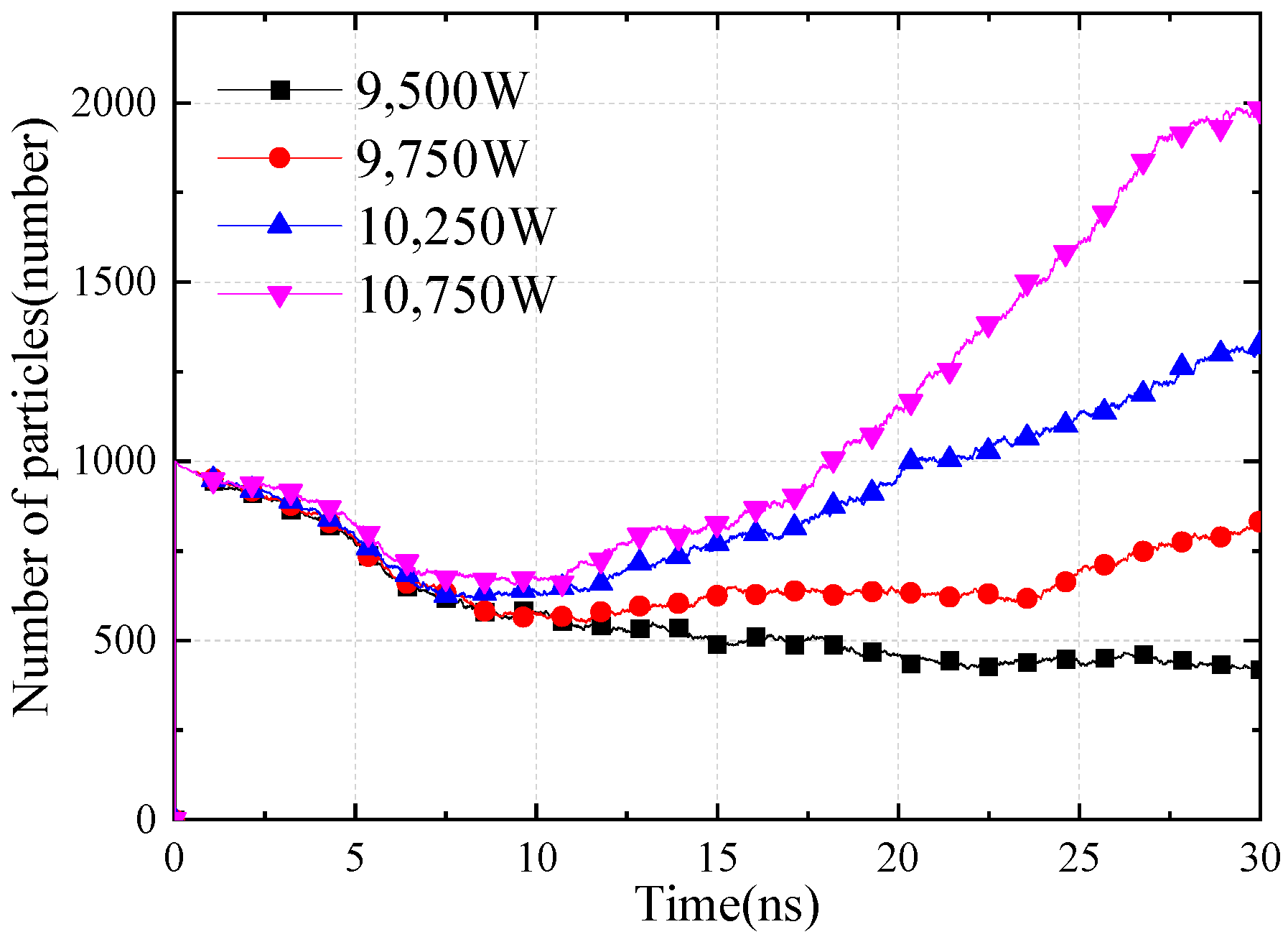
2.2.3. Multipactor Simulation
2.3. Design and Analysis
2.3.1. Coupler Analysis
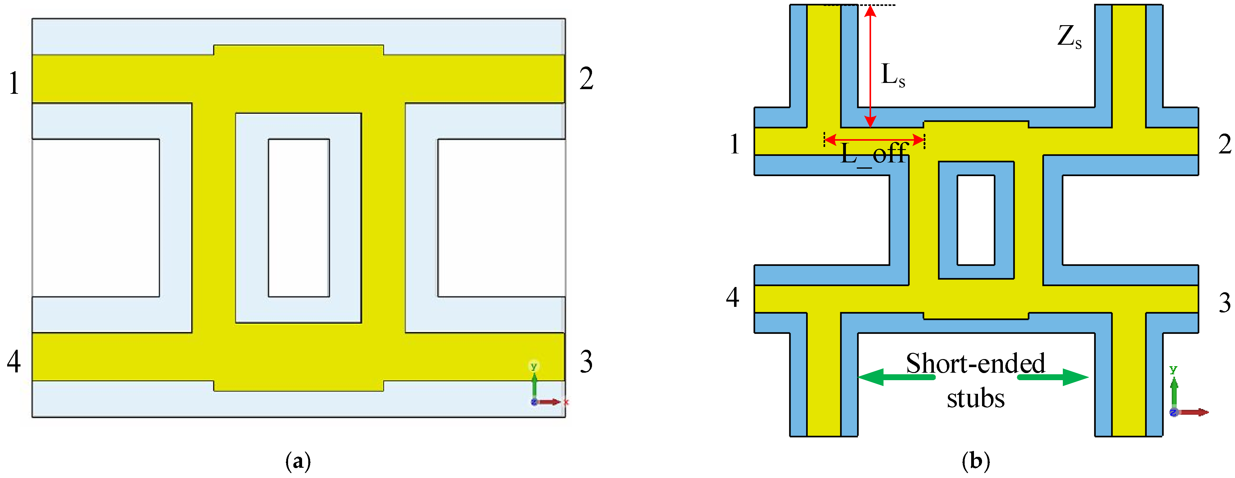
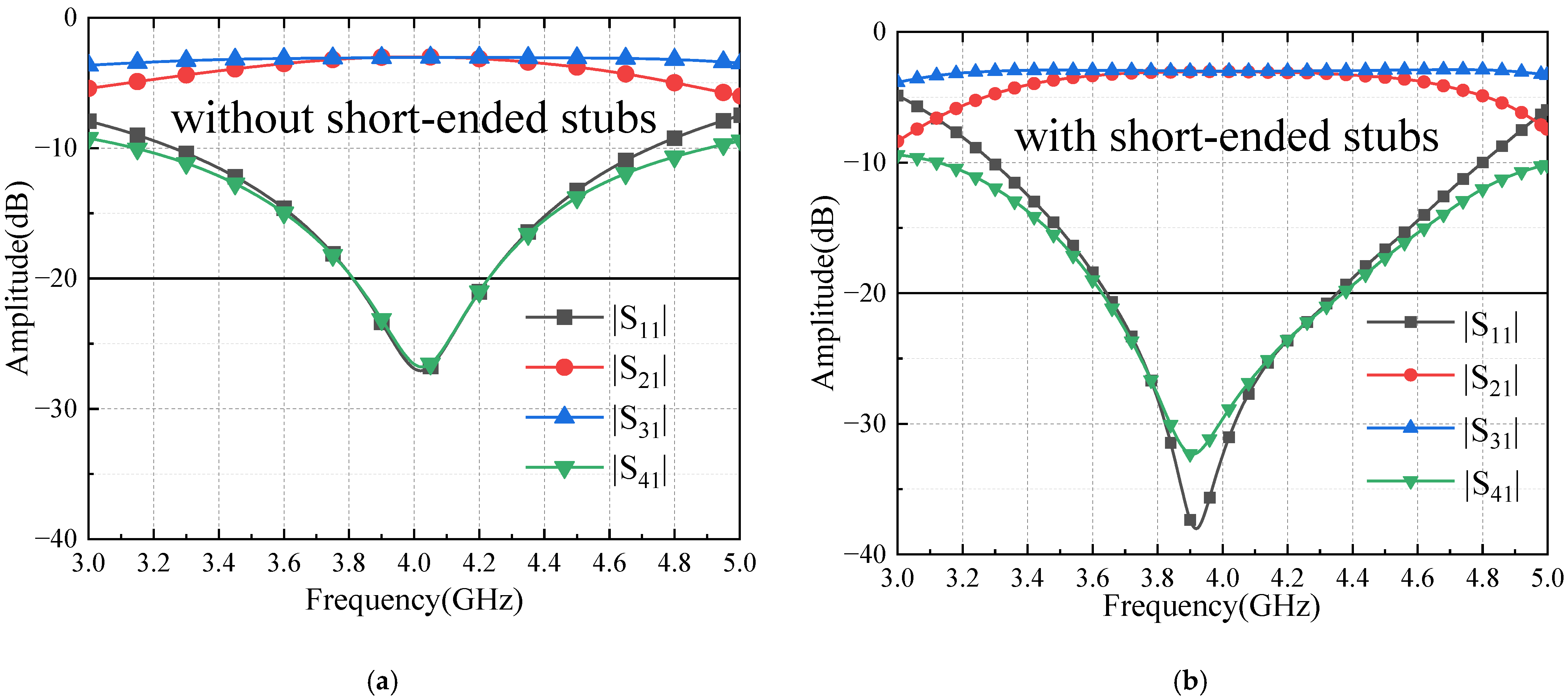
2.3.2. Crossover Analysis
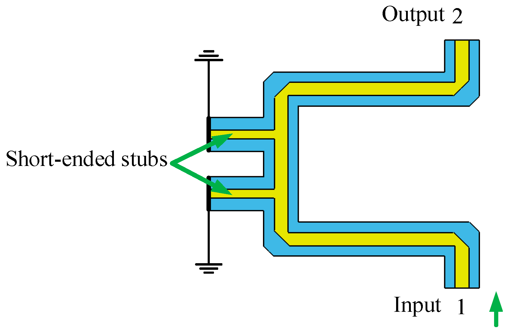
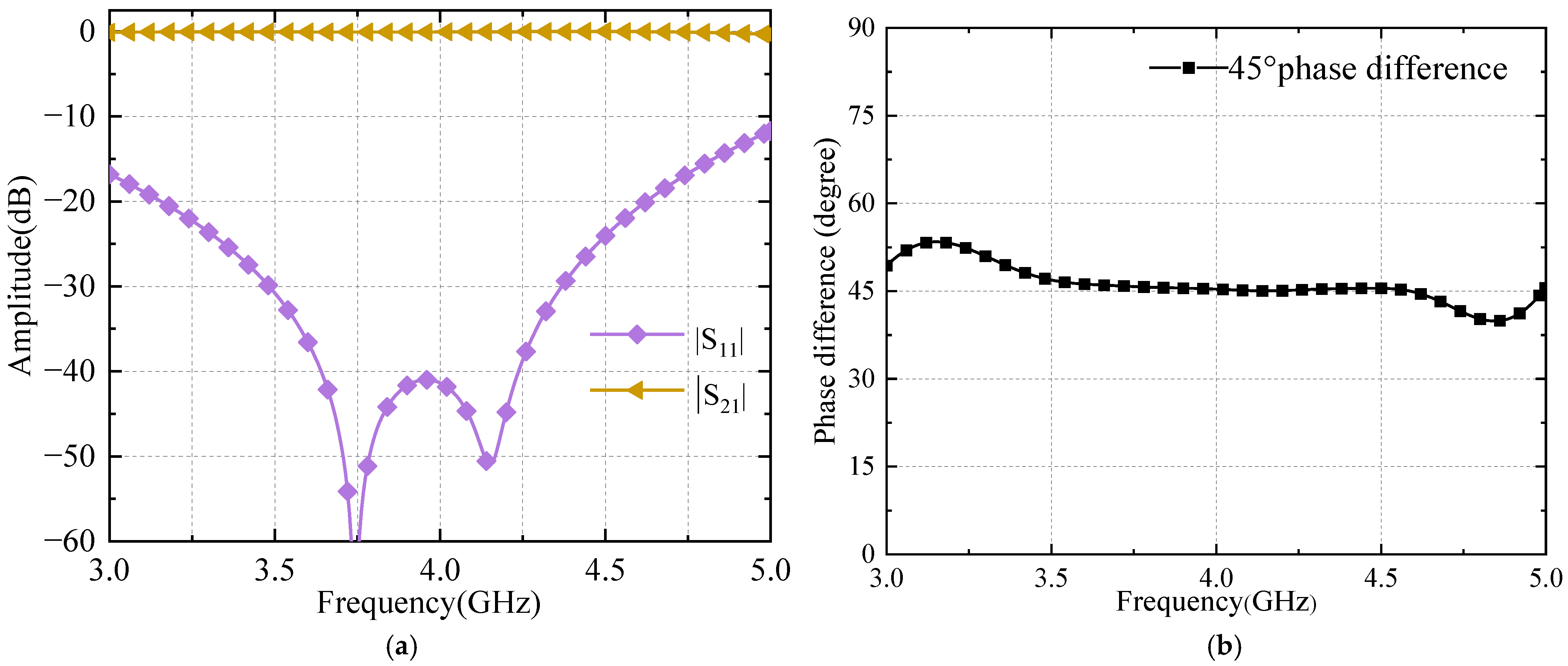
2.3.3. Phase Shifter Analysis
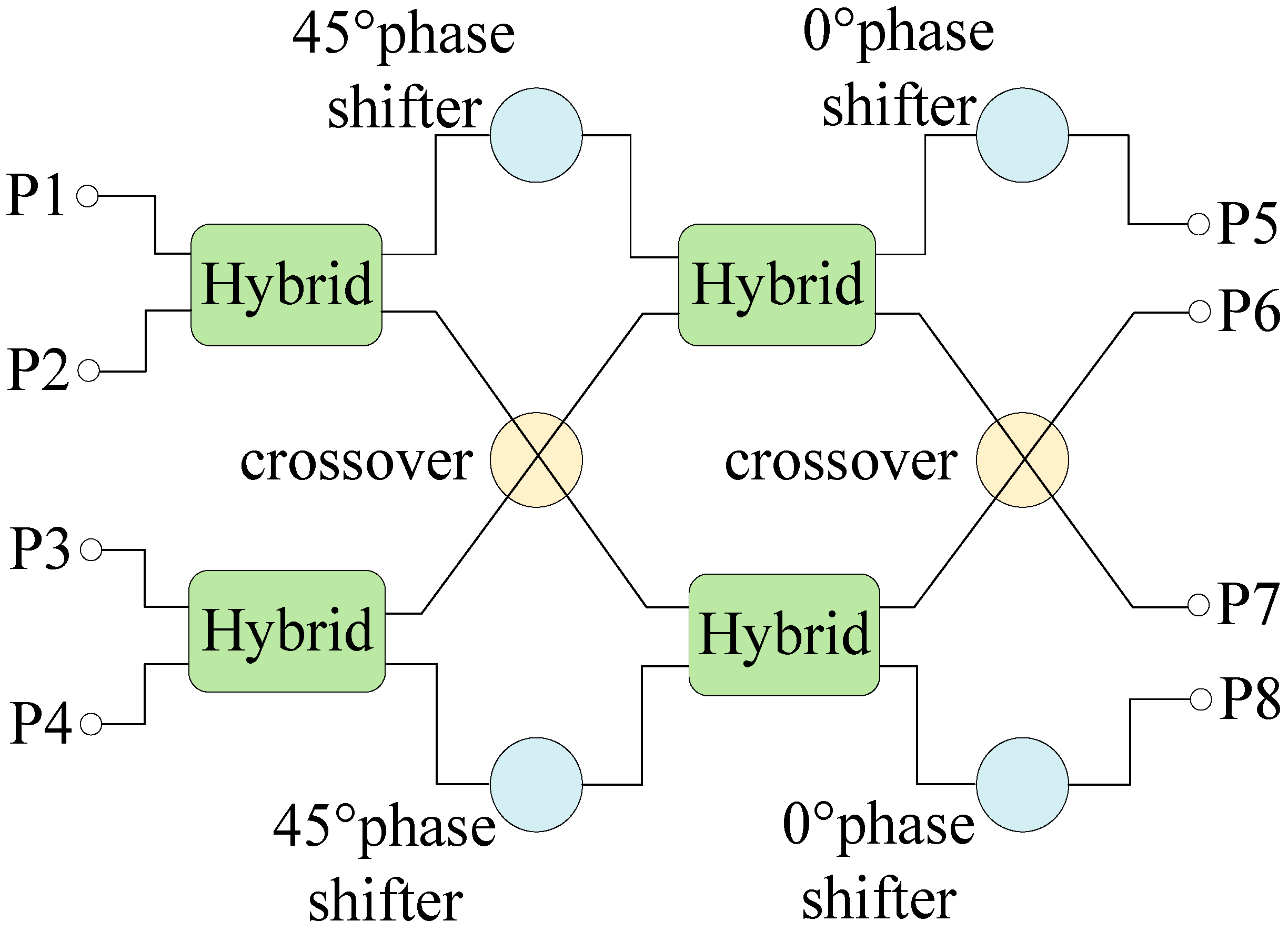
2.3.4. Butler Matrix Design
3. Results
3.1. Simulation
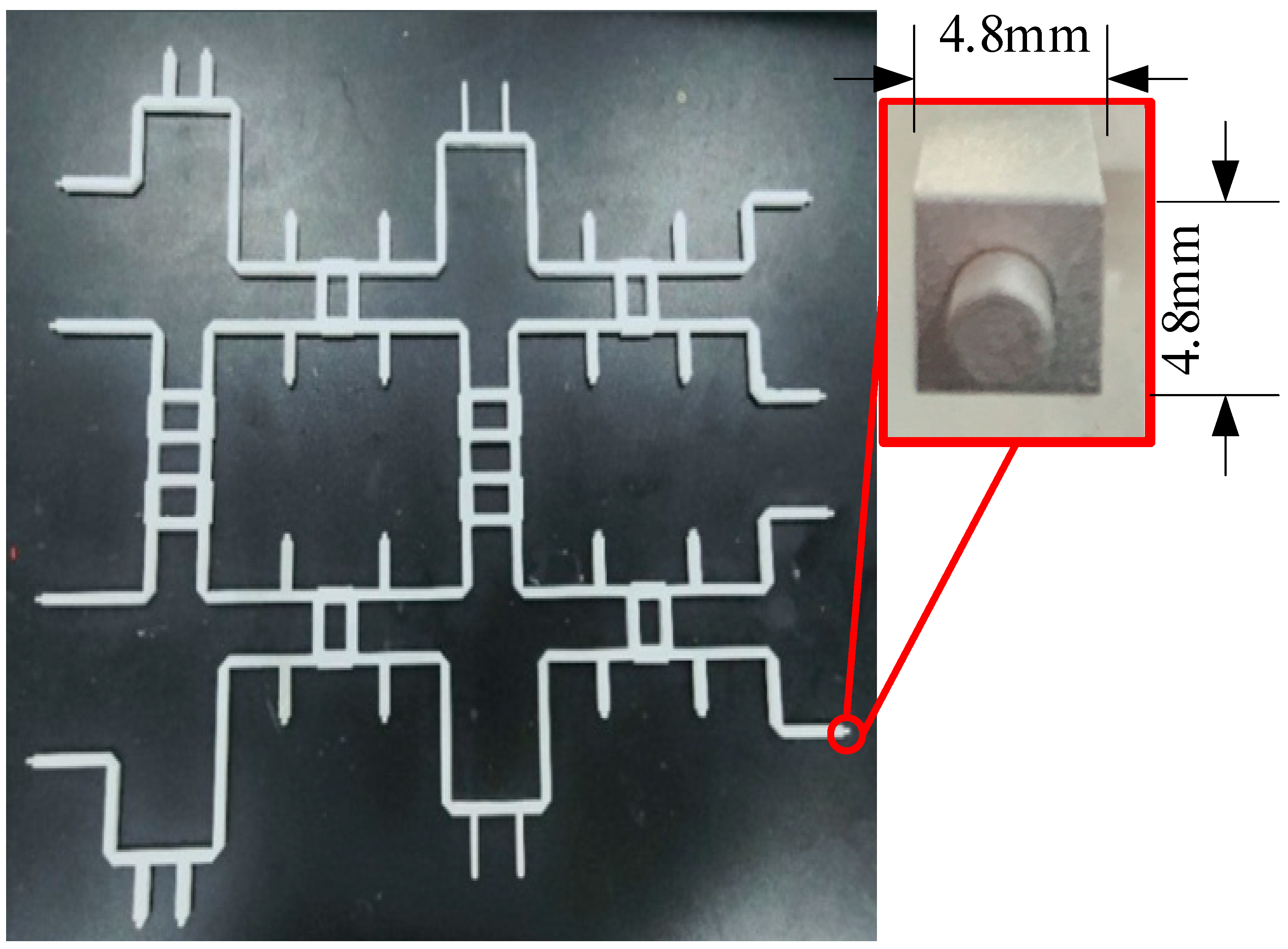
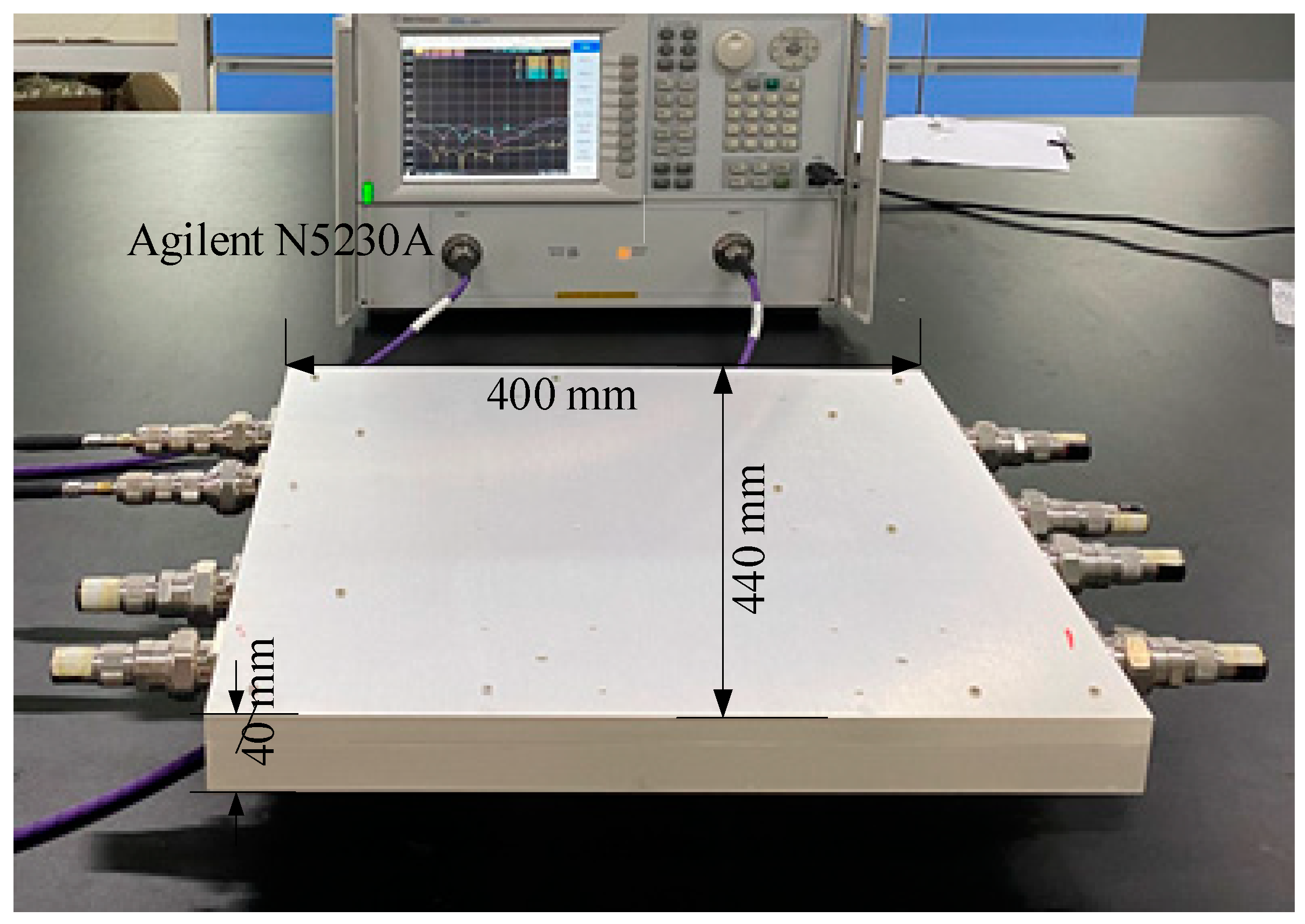
3.2. Measurement
4. Conclusions
Author Contributions
Funding
Institutional Review Board Statement
Informed Consent Statement
Data Availability Statement
Conflicts of Interest
References
- Vallappil, A.K.; Rahim, M.K.A.; Khawaja, B.A.; Murad, N.A.; Mustapha, M.G. Butler Matrix Based Beamforming Networks for Phased Array Antenna Systems: A Comprehensive Review and Future Directions for 5G Applications. IEEE Access 2021, 9, 3970–3987. [Google Scholar] [CrossRef]
- Li, P.; Ren, H.; Arigong, B. A Symmetric Beam-Phased Array Fed by a Nolen Matrix Using 180° Couplers. IEEE Microw. Wirel. Compon. Lett. 2020, 30, 387–390. [Google Scholar] [CrossRef]
- Sakhiya, R.; Chowdhury, S. A Low-Loss, 77 GHz, 8 × 8 Microstrip Butler Matrix on a High-Purity Fused-Silica (HPFS) Glass Substrate. Sensors 2023, 23, 1418. [Google Scholar] [CrossRef] [PubMed]
- Shallah, A.B.; Zubir, F.; Rahim, M.K.A.; Majid, H.A.; Sheikh, U.U.; Murad, N.A.; Yusoff, Z. Recent Developments of Butler Matrix from Components Design Evolution to System Integration for 5G Beamforming Applications: A Survey. IEEE Access 2022, 10, 88434–88456. [Google Scholar] [CrossRef]
- Rao, L.; Pant, M.; Malviya, L.; Parmar, A.; Charhate, S.V. 5G beamforming techniques for the coverage of intended directions in modern wireless communication: In-depth review. Int. J. Microw. Wirel. Technol. 2021, 13, 1039–1062. [Google Scholar] [CrossRef]
- Imani, A.; Bayati, M.S. A novel design of compact broadband 4 × 4 Butler matrix-based beamforming antenna array for C-band applications. Aeu-Int. J. Electron. Commun. 2021, 138, 153901. [Google Scholar] [CrossRef]
- Qiu, L.; Zhu, L.; Ouyang, Z.; Deng, L. Wideband Butler Matrix Based on Dual-Layer HMSIW for Enhanced Miniaturization. IEEE Microw. Wirel. Compon. Lett. 2022, 32, 25–28. [Google Scholar] [CrossRef]
- Nasseri, H.; Bemani, M.; Ghaffarlou, A. A New Method for Arbitrary Amplitude Distribution Generation in 4 × 8 Butler Matrix. IEEE Microw. Wirel. Compon. Lett. 2020, 30, 249–252. [Google Scholar] [CrossRef]
- Palazzi, V.; Cicioni, A.; Alimenti, F.; Mezzanotte, P.; Tentzeris, M.M.; Roselli, L. Compact 3-D-Printed 4 × 4 Butler Matrix Based on Low-Cost and Curing-Free Additive Manufacturing. IEEE Microw. Wirel. Compon. Lett. 2021, 31, 125–128. [Google Scholar] [CrossRef]
- Mohan, M.P.; Cai, H.; Alphones, A.; Karim, M.F. mmWave Zero Order Resonant Antenna with Patch-Like Radiation Fed by a Butler Matrix for Passive Beamforming. Sensors 2023, 23, 7973. [Google Scholar] [CrossRef]
- Jeon, M.; Seo, Y.; Cho, J.; Lee, C.; Jang, J.; Lee, Y.; Kwon, H.; Kahng, S. Investigation on Beam Alignment of a Microstrip-Line Butler Matrix and an SIW Butler Matrix for 5G Beamforming Antennas through RF-to-RF Wireless Sensing and 64-QAM Tests. Sensors 2021, 21, 6830. [Google Scholar] [CrossRef] [PubMed]
- Paul, T.; Harinath, M.; Garg, S.K.; Aich, S.; Kumar, A.; Trivedi, J.; Kumar, A.; Patel, M.K.; Rao, C.V.N.; Jyoti, R. Miniaturized High-Power Beam Steering Network Using Novel Nonplanar Waveguide Butler Matrix. IEEE Microw. Wirel. Compon. Lett. 2021, 31, 678–681. [Google Scholar] [CrossRef]
- Kim, S.; Choi, D. Analysis of Beamforming Antenna for Practical Indoor Location-Tracking Application. Sensors 2019, 19, 3040. [Google Scholar] [CrossRef] [PubMed]
- Tsao, Y.; Hsu, H.; Desai, A. High power handling GaAs SP4T Switch-based Beam-Switching planar antenna module for 5G New-Radio FR2 applications. Aeu-Int. J. Electron. Commun. 2023, 159, 154494. [Google Scholar] [CrossRef]
- Alessandri, F.; Mongiardo, M.; Sorrentino, R. Computer-aided-design of beam forming networks for modern satellite antennas. IEEE Trans. Microw. Theory Tech. 1992, 40, 1117–1127. [Google Scholar] [CrossRef]
- Sandoval, J.J.M. Mm-Wave Reconfigurable Antenna Arrays, Phase Shifters and Beamforming Networks with Reduced Hardware Complexity Using Integrated Microfluidic Actuation; Engineering University of South Florida: Tampa, FL, USA, 2022. [Google Scholar]
- Pandey, B.K.; Kulshrestha, S.; Dey, R.; Chakrabarty, S.B.; Sharma, S.B. Square Coaxial Beam Forming Network for Multilayer Microstrip Antenna. In Proceedings of the 2007 Asia Pacific Microwave Conference, Bangkok, Thailand, 11–14 December 2007; Volumes 1–5, pp. 1226–1229. [Google Scholar]
- Li, Y.; Wang, D.; Yu, M.; He, Y.; Cui, W. Experimental Verification of Multipactor Discharge Dynamics between Ferrite Dielectric and Metal. IEEE Trans. Electron Devices 2018, 65, 4592–4599. [Google Scholar] [CrossRef]
- Pezhman, M.M.; Heidari, A.-A.; Ghafoorzadeh-Yazdi, A. A compact 4 × 4 SIW beamforming network for 5G applications. Aeu-Int. J. Electron. Commun. 2021, 135, 153714. [Google Scholar] [CrossRef]
- Guo, Y.J.; Ansari, M.; Fonseca, N.J.G. Circuit Type Multiple Beamforming Networks for Antenna Arrays in 5G and 6G Terrestrial and Non-Terrestrial Networks. IEEE J. Microw. 2021, 1, 704–722. [Google Scholar] [CrossRef]
- Lau, K.H. Loss calculations for rectangular coaxial lines. Proc. Inst. Elect. Eng. Microw. Antennas Propag. 1988, 135, 207–209. [Google Scholar] [CrossRef]
- Wu, C.B.; Sun, Q.F.; Luo, Y.H.; Li, Z.J. Studies of multipactor threshold in square coaxial lines. In Proceedings of the 2000 5th International Symposium on Antennas, Propagation and Em Theory, Beijing, China, 15–18 August 2000; pp. 422–425. [Google Scholar]
- Feng, W.; Duan, X.; Shi, Y.; Zhou, X.Y.; Che, W. Dual-Band Branch-Line Couplers with Short/Open-Ended Stubs. IEEE Trans. Circuits Syst. II 2020, 67, 2497–2501. [Google Scholar] [CrossRef]
- Dong, L.; Lv, Y.; Xiao, H.; Lu, J.; Jiang, Y.; Li, Y. Micro-rectangular Coaxial Structure-based Broadband Millimeter-wave Power Divider. In Proceedings of the 2020 21st International Conference on Electronic Packaging Technology (Icept) 2020, Guangzhou, China, 12–15 August 2020. [Google Scholar]
- Sa’Ad, B.M.; Rahim, S.K.A.; Peter, T.; Bin Abdul Rani, M.S.; Ausordin, S.F.; Zaidel, D.N.A.; Krishnan, C. Transparent Branch-Line Coupler Using Micro-Metal Mesh Conductive Film. IEEE Microw. Wirel. Compon. Lett. 2014, 24, 857–859. [Google Scholar] [CrossRef]
- Ding, K.; Kishk, A. Wideband Hybrid Coupler with Electrically Switchable Phase-Difference Performance. IEEE Microw. Wirel. Compon. Lett. 2017, 27, 992–994. [Google Scholar] [CrossRef]
- Alnahwi, F.M.; Al-Yasir, Y.I.A.; See, C.H.; Abdullah, A.S.; Abd-Alhameed, R.A. Generalized Concept and MATLAB Code for Modeling and Analyzing Wideband 90° Stub-Loaded Phase Shifters with Simulation and Experimental Verifications. Sensors 2023, 23, 7773. [Google Scholar] [CrossRef] [PubMed]
- Prakash, V.; Dahiya, S.; Kumawat, S.; Singh, P. Design of 4 × 4 Butler Matrix and Its Process Modeling Using Petri Nets for Phase Array Systems. Prog. Electromag. Res. C 2020, 103, 137–153. [Google Scholar] [CrossRef]
- Menargues, E.; Sirci, S.; Calleau, A.; Dimitriades, A. High-power tests in Additive Manufacturing Ka-band feeds and feed components. In Proceedings of the 2023 International Conference Electromagnetics in Advanced Applications (ICEAA), Venice, Italy, 9–13 October 2023. [Google Scholar]
- Bekasiewicz, A.; Koziel, S. Low-Cost Unattended Design of Miniaturized 4 × 4 Butler Matrices with Nonstandard Phase Differences. Sensors 2021, 21, 851. [Google Scholar] [CrossRef] [PubMed]
- García-Patrón, M.; Rodríguez, M.; Ruiz-Cruz, J.A.; Montero, I. Uncertainty Budget in Microwave High-Power Testing. IEEE Trans. Instrum. Meas. 2023, 72, 1–12. [Google Scholar] [CrossRef]
- Monerris-Belda, O.; Marin, R.C.; Jodar, M.R.; Diaz-Caballero, E.; Guillen, C.A.; Petit, J.; Vicente, E.B.; Gimeno, B.; Raboso, D. High Power RF Discharge Detection Technique Based on the In-Phase and Quadrature Signals. IEEE Trans. Microw. Theory Tech. 2021, 69, 5429–5438. [Google Scholar] [CrossRef]


Disclaimer/Publisher’s Note: The statements, opinions and data contained in all publications are solely those of the individual author(s) and contributor(s) and not of MDPI and/or the editor(s). MDPI and/or the editor(s) disclaim responsibility for any injury to people or property resulting from any ideas, methods, instructions or products referred to in the content. |
© 2024 by the authors. Licensee MDPI, Basel, Switzerland. This article is an open access article distributed under the terms and conditions of the Creative Commons Attribution (CC BY) license (https://creativecommons.org/licenses/by/4.0/).
Share and Cite
Li, J.; Yan, L.; Liu, C.; Bai, H.; Cui, W. Design and Implementation of C-Band Large-Power Planar Butler Matrix in SRS. Sensors 2024, 24, 2132. https://doi.org/10.3390/s24072132
Li J, Yan L, Liu C, Bai H, Cui W. Design and Implementation of C-Band Large-Power Planar Butler Matrix in SRS. Sensors. 2024; 24(7):2132. https://doi.org/10.3390/s24072132
Chicago/Turabian StyleLi, Jinfeng, Liping Yan, Changjun Liu, He Bai, and Wanzhao Cui. 2024. "Design and Implementation of C-Band Large-Power Planar Butler Matrix in SRS" Sensors 24, no. 7: 2132. https://doi.org/10.3390/s24072132
APA StyleLi, J., Yan, L., Liu, C., Bai, H., & Cui, W. (2024). Design and Implementation of C-Band Large-Power Planar Butler Matrix in SRS. Sensors, 24(7), 2132. https://doi.org/10.3390/s24072132