
A Performance Comparison between Different Industrial Real-Time Indoor Localization Systems for Mobile Platforms
 ,
,  ,
,  ,
,  , and
, and
Abstract
1. Introduction
2. Related Work
3. Localization Techniques and Methods
3.1. Localization Techniques
3.1.1. Time of Flight (ToF)
3.1.2. Angle of Arrival (AoA)
3.1.3. Time Difference of Arrival (TDoA)
3.2. Localization Methods
3.2.1. Ultra-Wideband (UWB)
3.2.2. Ultrasound (US)
4. Methodology
4.1. Testing Scenario and Indoor Localization Systems
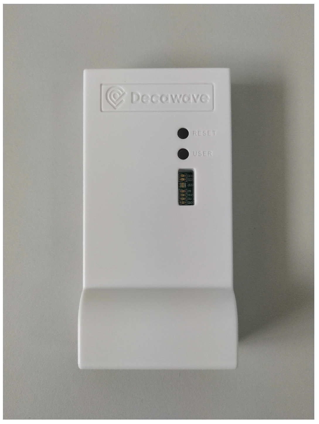
4.1.1. Qorvo
4.1.2. Eliko Kio
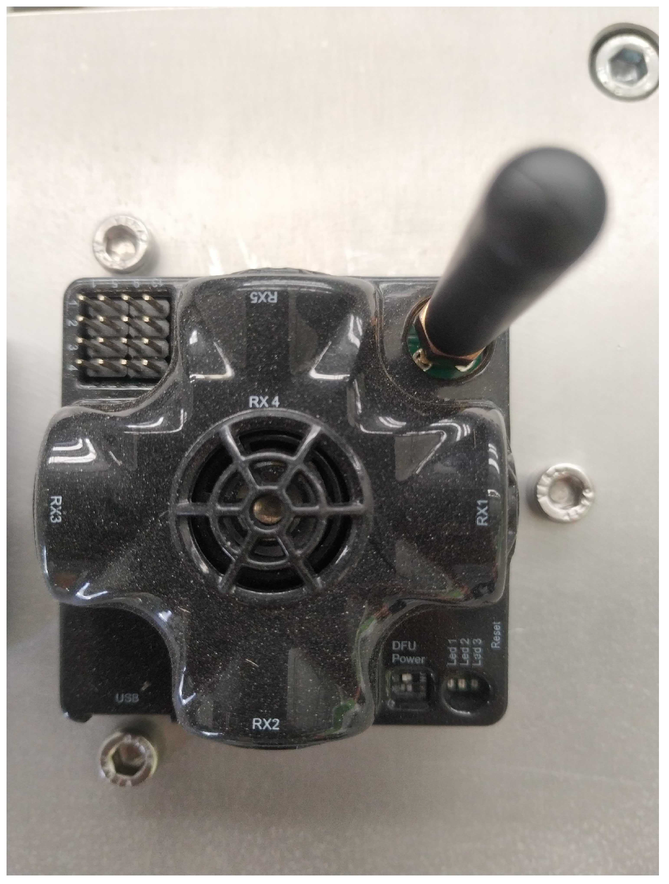
4.1.3. Marvelmind
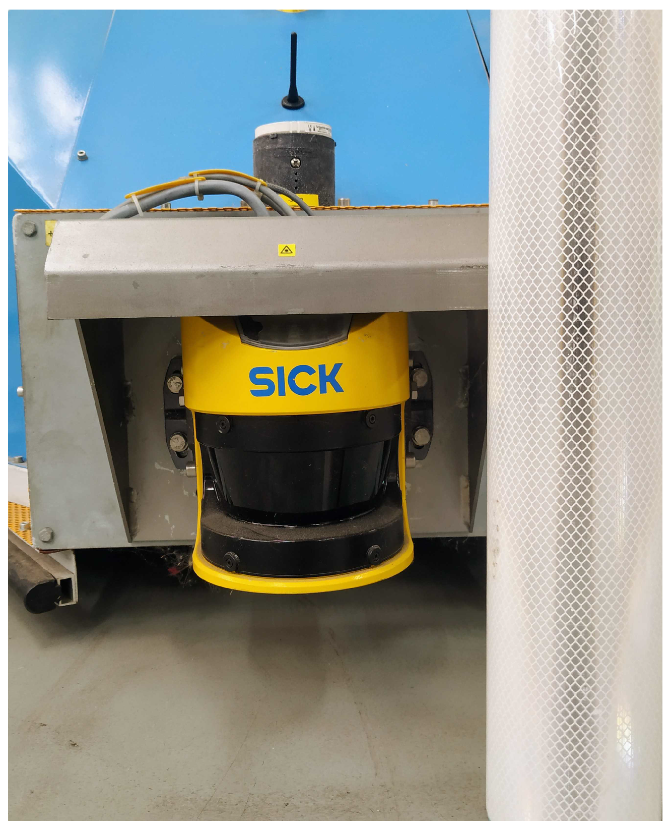
4.1.4. EKF Beacons—Ground Truth
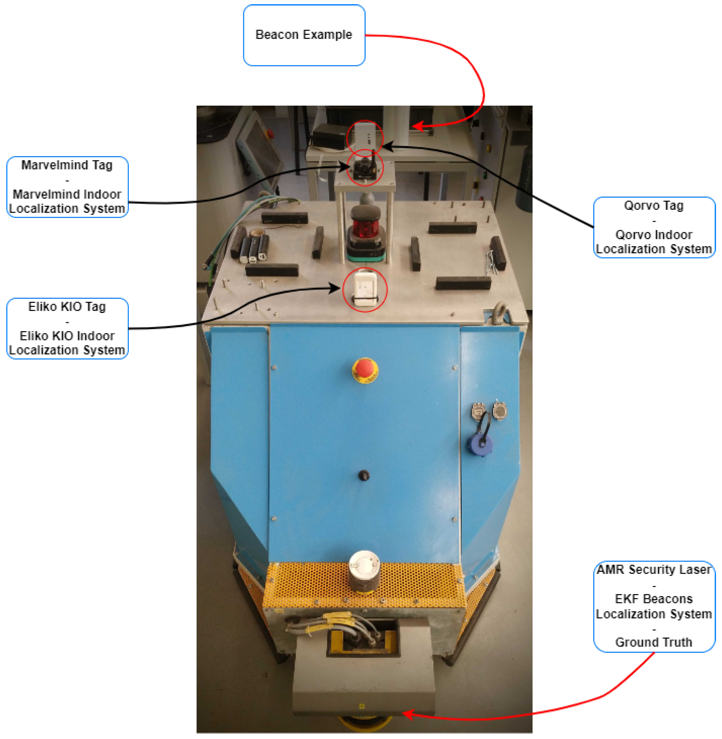
4.1.5. Industrial Scenario—Systems Integration
4.1.6. Autonomous Mobile Robot—Systems Integration
4.2. Data Acquisition
4.2.1. Beacons Data
4.2.2. Marvelmind
4.2.3. Eliko Kio
4.2.4. Qorvo
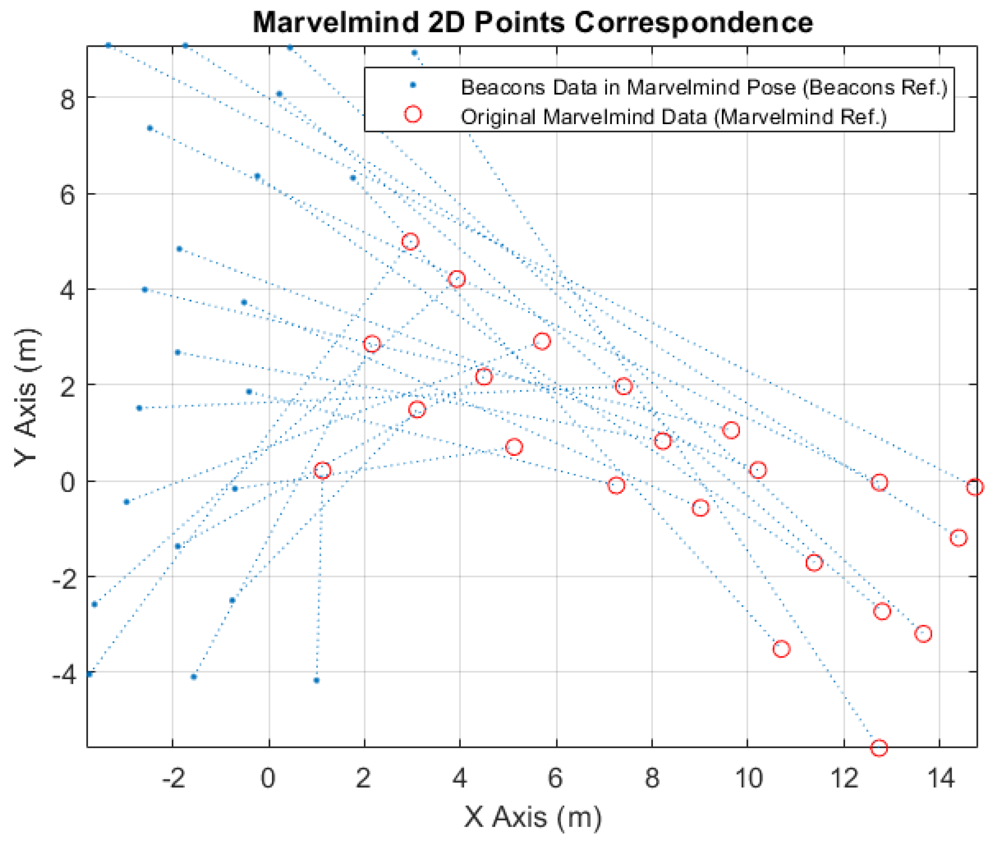
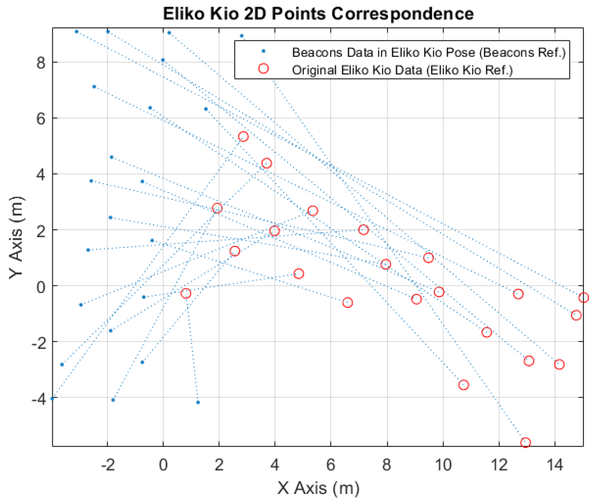
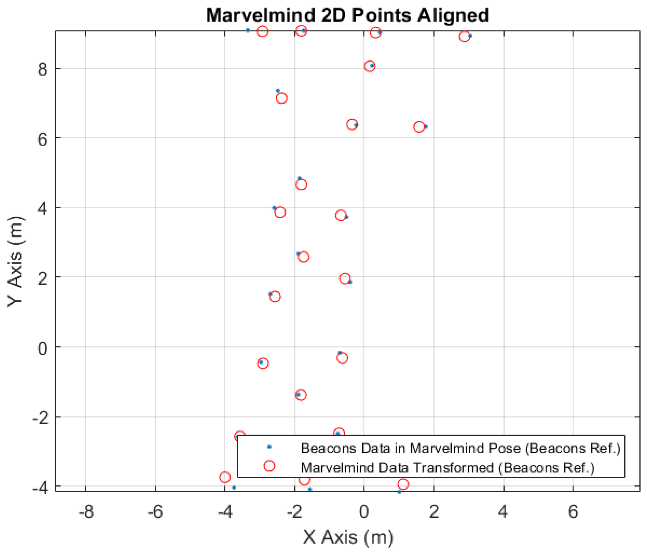
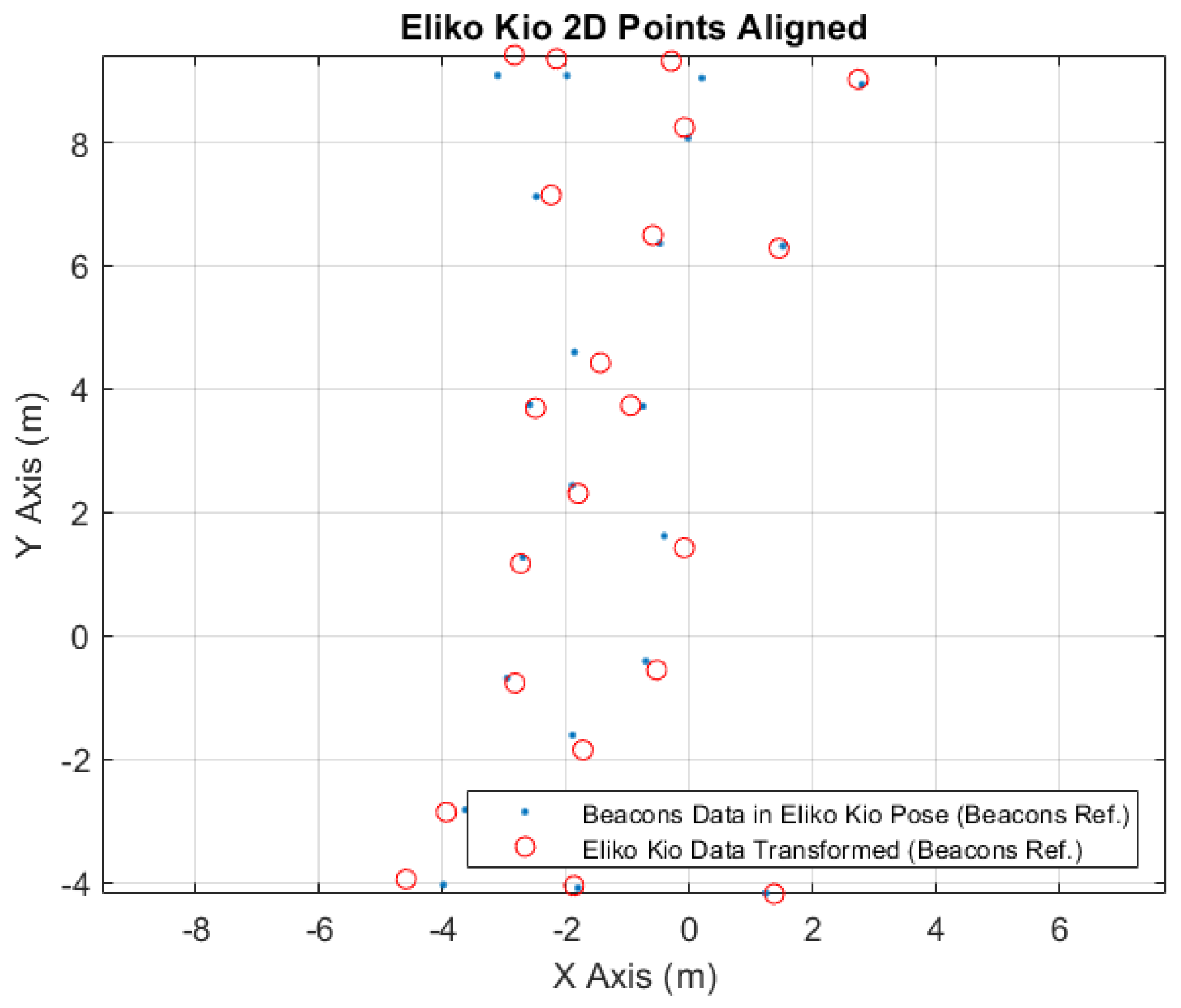
4.3. Data Transformation
4.3.1. Marvelmind
4.3.2. Eliko Kio
4.3.3. Qorvo
5. Results
6. Conclusions
Author Contributions
Funding
Institutional Review Board Statement
Informed Consent Statement
Data Availability Statement
Acknowledgments
Conflicts of Interest
Abbreviations
| AGV | Autonomous Guided Vehicle |
| AMR | Autonomous Mobile Robots |
| AoA | Angle of Arrival |
| API | Application Programming Interface |
| BLE | Bluetooth Low Energy |
| EKF | Extended Kalman Filter |
| EU | European Union |
| GPS | Global Positioning System |
| ID | Identification Number |
| IMUs | Inertial Measurement Units |
| IoT | Internet of Things |
| IR | Infrared |
| LS | Least Squares |
| MDPI | Multidisciplinary Digital Publishing Institute |
| ML | Machine Learning |
| MP | Mobile Platform |
| RF | Radio Frequency |
| RFID | Radio Frequency IDentification |
| RSS | Received Signal Strength |
| RSSI | Received Signal Strength Indicator |
| RVIZ | Robot Operating System Visualization |
| TDoA | Time Difference of Arrival |
| TEA* | Time Enhanced A* |
| 3D | Three-Dimensional |
| ToA | Time of Arrival |
| ToF | Time of Flight |
| 2D | Two-Dimensional |
| UHF | Ultra High Frequency |
| US | Ultrasound |
| UWB | Ultra-Wideband |
| WLAN | Wireless Local Area Network |
References
- Moura, P.; Costa, P.; Lima, J.; Costa, P. A temporal optimization applied to time enhanced A. In AIP Conference Proceedings; AIP Publishing LLC: College Park, MD, USA, 2019; Volume 2116, p. 220007. [Google Scholar]
- Santos, J.; Costa, P.; Rocha, L.F.; Moreira, A.P.; Veiga, G. Time enhanced A*: Towards the development of a new approach for Multi-Robot Coordination. In Proceedings of the 2015 IEEE International Conference on Industrial Technology (ICIT), Seville, Spain, 17–19 March 2015; pp. 3314–3319. [Google Scholar]
- Cardarelli, E.; Digani, V.; Sabattini, L.; Secchi, C.; Fantuzzi, C. Cooperative cloud robotics architecture for the coordination of multi-AGV systems in industrial warehouses. Mechatronics 2017, 45, 1–13. [Google Scholar] [CrossRef]
- Butdee, S.; Suebsomran, A. Localization based on matching location of AGV. In Proceedings of the 24th International Manufacturing Conference, IMC24. Waterford Institute of Technology, Waterford, Ireland, 20–30 August 2007; pp. 1121–1128. [Google Scholar]
- Roy, P.; Chowdhury, C. A survey of machine learning techniques for indoor localization and navigation systems. J. Intell. Robot. Syst. 2021, 101, 63. [Google Scholar] [CrossRef]
- Zafari, F.; Gkelias, A.; Leung, K.K. A survey of indoor localization systems and technologies. IEEE Commun. Surv. Tutor. 2019, 21, 2568–2599. [Google Scholar] [CrossRef]
- Bradley, C.; El-Tawab, S.; Heydari, M.H. Security analysis of an IoT system used for indoor localization in healthcare facilities. In Proceedings of the 2018 Systems and Information Engineering Design Symposium (SIEDS), Charlottesville, VA, USA, 27 April 2018; pp. 147–152. [Google Scholar]
- Shit, R.C.; Sharma, S.; Yelamarthi, K.; Puthal, D. AI-enabled fingerprinting and crowdsource-based vehicle localization for resilient and safe transportation systems. IEEE Trans. Intell. Transp. Syst. 2021, 22, 4660–4669. [Google Scholar] [CrossRef]
- Obeidat, H.; Shuaieb, W.; Obeidat, O.; Abd-Alhameed, R. A review of indoor localization techniques and wireless technologies. Wirel. Pers. Commun. 2021, 119, 289–327. [Google Scholar] [CrossRef]
- Pilati, F.; Sbaragli, A.; Nardello, M.; Santoro, L.; Fontanelli, D.; Brunelli, D. Indoor positioning systems to prevent the COVID19 transmission in manufacturing environments. Procedia Cirp 2022, 107, 1588–1593. [Google Scholar] [CrossRef]
- Xiong, R.; van Waasen, S.; Rheinlnder, C.; Wehn, N. Development of a Novel Indoor Positioning System With mm-Range Precision Based on RF Sensors Network. IEEE Sens. Lett. 2017, 1, 5500504. [Google Scholar] [CrossRef]
- Li, N.; Becerik-Gerber, B. An infrastructure-free indoor localization framework to support building emergency response operations. In Proceedings of the 19th EG-ICE International Workshop on Intelligent Computing in Engineering, Munich, Germany, 4–6 July 2012. [Google Scholar]
- Wang, S.; Zhao, L. Optimization of Goods Location Numbering and Storage and Retrieval Sequence in Automated Warehouse. In Proceedings of the 2009 International Joint Conference on Computational Sciences and Optimization, Sanya, China, 24–26 April 2009; Volume 2, pp. 883–886. [Google Scholar] [CrossRef]
- Lipka, M.; Sippel, E.; Hehn, M.; Adametz, J.; Vossiek, M.; Dobrev, Y.; Gulden, P. Wireless 3D Localization Concept for Industrial Automation Based on a Bearings Only Extended Kalman Filter. In Proceedings of the 2018 Asia-Pacific Microwave Conference (APMC), Kyoto, Japan, 6–9 November 2018; pp. 821–823. [Google Scholar] [CrossRef]
- Hesslein, N.; Wesselhöft, M.; Hinckeldeyn, J.; Kreutzfeldt, J. Industrial indoor localization: Improvement of logistics processes using location based services. In Advances in Automotive Production Technology–Theory and Application: Stuttgart Conference on Automotive Production (SCAP2020); Springer: Berlin/Heidelberg, Germany, 2021; pp. 460–467. [Google Scholar]
- Xu, L.; Shen, X.; Han, T.X.; Du, R.; Shen, Y. An Efficient Relative Localization Method via Geometry-based Coordinate System Selection. In Proceedings of the ICC 2022-IEEE International Conference on Communications, Seoul, Republic of Korea, 16–20 May 2022; pp. 4522–4527. [Google Scholar] [CrossRef]
- Luo, Q.; Yang, K.; Yan, X.; Li, J.; Wang, C.; Zhou, Z. An Improved Trilateration Positioning Algorithm with Anchor Node Combination and K-Means Clustering. Sensors 2022, 22, 6085. [Google Scholar] [CrossRef]
- Thrun, S.; Burgard, W.; Fox, D. Probabilistic Robotics (Intelligent Robotics and Autonomous Agents); The MIT Press: Cambridge, MA, USA, 2005. [Google Scholar]
- Kim, S.H.; Roh, C.W.; Kang, S.C.; Park, M.Y. Outdoor navigation of a mobile robot using differential GPS and curb detection. In Proceedings of the 2007 IEEE International Conference on Robotics and Automation, Rome, Italy, 10–14 April 2007; pp. 3414–3419. [Google Scholar]
- Gonzalez, J.; Blanco, J.; Galindo, C.; Ortiz-de Galisteo, A.; Fernández-Madrigal, J.; Moreno, F.; Martinez, J. Combination of UWB and GPS for indoor-outdoor vehicle localization. In Proceedings of the 2007 IEEE International Symposium on Intelligent Signal Processing, Alcala de Henares, Spain, 3–5 October 2007; pp. 1–6. [Google Scholar]
- Hahnel, D.; Burgard, W.; Fox, D.; Fishkin, K.; Philipose, M. Mapping and localization with RFID technology. In Proceedings of the IEEE International Conference on Robotics and Automation, 2004. Proceedings. ICRA’04, New Orleans, LA, USA, 26 April–1 May 2004; Volume 1, pp. 1015–1020. [Google Scholar]
- Choi, B.S.; Lee, J.W.; Lee, J.J.; Park, K.T. A hierarchical algorithm for indoor mobile robot localization using RFID sensor fusion. IEEE Trans. Ind. Electron. 2011, 58, 2226–2235. [Google Scholar] [CrossRef]
- Huh, J.; Chung, W.S.; Nam, S.Y.; Chung, W.K. Mobile robot exploration in indoor environment using topological structure with invisible barcodes. ETRI J. 2007, 29, 189–200. [Google Scholar] [CrossRef]
- Lin, G.; Chen, X. A Robot Indoor Position and Orientation Method based on 2D Barcode Landmark. J. Comput. 2011, 6, 1191–1197. [Google Scholar] [CrossRef]
- Kobayashi, H. A new proposal for self-localization of mobile robot by self-contained 2d barcode landmark. In Proceedings of the 2012 Proceedings of SICE annual conference (SICE), Akita, Japan, 20–23 August 2012; pp. 2080–2083. [Google Scholar]
- Atanasyan, A.; Roßmann, J. Improving Self-Localization Using CNN-based Monocular Landmark Detection and Distance Estimation in Virtual Testbeds. In Tagungsband des 4. Kongresses Montage Handhabung Industrieroboter; Springer: Berlin/Heidelberg, Germany, 2019; pp. 249–258. [Google Scholar]
- Kendall, A.; Grimes, M.; Cipolla, R. Posenet: A convolutional network for real-time 6-dof camera relocalization. In Proceedings of the IEEE International Conference on Computer Vision, Santiago, Chile, 7–13 December 2015; pp. 2938–2946. [Google Scholar]
- Sadeghi Esfahlani, S.; Sanaei, A.; Ghorabian, M.; Shirvani, H. The Deep Convolutional Neural Network Role in the Autonomous Navigation of Mobile Robots (SROBO). Remote Sens. 2022, 14, 3324. [Google Scholar] [CrossRef]
- Szegedy, C.; Liu, W.; Jia, Y.; Sermanet, P.; Reed, S.; Anguelov, D.; Erhan, D.; Vanhoucke, V.; Rabinovich, A. Going deeper with convolutions. In Proceedings of the 2015 IEEE Conference on Computer Vision and Pattern Recognition (CVPR), Boston, MA, USA, 7–12 June 2015; pp. 1–9. [Google Scholar] [CrossRef]
- Lima, J.; Rocha, C.; Rocha, L.; Costa, P. Data Matrix Based Low Cost Autonomous Detection of Medicine Packages. Appl. Sci. 2022, 12, 9866. [Google Scholar] [CrossRef]
- Sharma, P.; Saucan, A.A.; Bucci, D.J.; Varshney, P.K. On Self-Localization and Tracking with an Unknown Number of Targets. In Proceedings of the 2018 52nd Asilomar Conference on Signals, Systems, and Computers, Pacific Grove, CA, USA, 28–31 October 2018; pp. 1735–1739. [Google Scholar] [CrossRef]
- Ahmad, U.; Poon, K.; Altayyari, A.M.; Almazrouei, M.R. A Low-cost Localization System for Warehouse Inventory Management. In Proceedings of the 2019 International Conference on Electrical and Computing Technologies and Applications (ICECTA), Ras Al Khaimah, United Arab Emirates, 19–21 November 2019; pp. 1–5. [Google Scholar] [CrossRef]
- Halawa, F.; Dauod, H.; Lee, I.G.; Li, Y.; Yoon, S.W.; Chung, S. Introduction of a real time location system to enhance the warehouse safety and operational efficiency. Int. J. Prod. Econ. 2020, 224, 107541. [Google Scholar] [CrossRef]
- Coronado, E.; Kiyokawa, T.; Ricardez, G.A.G.; Ramirez-Alpizar, I.G.; Venture, G.; Yamanobe, N. Evaluating quality in human-robot interaction: A systematic search and classification of performance and human-centered factors, measures and metrics towards an industry 5.0. J. Manuf. Syst. 2022, 63, 392–410. [Google Scholar] [CrossRef]
- Martinho, R.; Lopes, J.; Jorge, D.; de Oliveira, L.C.; Henriques, C.; Peças, P. IoT Based Automatic Diagnosis for Continuous Improvement. Sustainability 2022, 14, 9687. [Google Scholar] [CrossRef]
- Le, D.V.; Havinga, P.J. SoLoc: Self-organizing indoor localization for unstructured and dynamic environments. In Proceedings of the 2017 International Conference on Indoor Positioning and Indoor Navigation (IPIN), Sapporo, Japan, 18–21 September 2017; pp. 1–8. [Google Scholar] [CrossRef]
- Flögel, D.; Bhatt, N.P.; Hashemi, E. Infrastructure-Aided Localization and State Estimation for Autonomous Mobile Robots. Robotics 2022, 11, 82. [Google Scholar] [CrossRef]
- Alkendi, Y.; Seneviratne, L.; Zweiri, Y. State of the Art in Vision-Based Localization Techniques for Autonomous Navigation Systems. IEEE Access 2021, 9, 76847–76874. [Google Scholar] [CrossRef]
- Dias, F.; Schafer, H.; Natal, L.; Cardeira, C. Mobile Robot Localisation for Indoor Environments Based on Ceiling Pattern Recognition. In Proceedings of the 2015 IEEE International Conference on Autonomous Robot Systems and Competitions, Vila Real, Portugal, 8–10 April 2015; pp. 65–70. [Google Scholar] [CrossRef]
- Sudin, M.; Abdullah, S.; Nasudin, M. Humanoid Localization on Robocup Field using Corner Intersection and Geometric Distance Estimation. IJIMAI 2019, 5, 50–56. [Google Scholar] [CrossRef]
- Kalaitzakis, M.; Cain, B.; Carroll, S.; Ambrosi, A.; Whitehead, C.; Vitzilaios, N. Fiducial markers for pose estimation. J. Intell. Robot. Syst. 2021, 101, 71. [Google Scholar] [CrossRef]
- Grilo, A.; Costa, R.; Figueiras, P.; Gonçalves, R.J. Analysis of AGV indoor tracking supported by IMU sensors in intra-logistics process in automotive industry. In Proceedings of the 2021 IEEE International Conference on Engineering, Technology and Innovation (ICE/ITMC), Cardiff, UK, 21–23 June 2021; pp. 1–7. [Google Scholar] [CrossRef]
- Malyavej, V.; Kumkeaw, W.; Aorpimai, M. Indoor robot localization by RSSI/IMU sensor fusion. In Proceedings of the 2013 10th International Conference on Electrical Engineering/Electronics, Computer, Telecommunications and Information Technology, Krabi, Thailand, 15–17 May 2013; pp. 1–6. [Google Scholar] [CrossRef]
- Xia, Z.; Chen, C. A Localization Scheme with Mobile Beacon for Wireless Sensor Networks. In Proceedings of the 2006 6th International Conference on ITS Telecommunications, Chengdu, China, 21–23 June 2006; pp. 1017–1020. [Google Scholar] [CrossRef]
- Zhao, C.; Wang, B. A UWB/Bluetooth Fusion Algorithm for Indoor Localization. In Proceedings of the 2019 Chinese Control Conference (CCC), Guangzhou, China, 27–30 July 2019; pp. 4142–4146. [Google Scholar] [CrossRef]
- Álvarez Merino, C.S.; Luo-Chen, H.Q.; Khatib, E.J.; Barco, R. WiFi FTM, UWB and Cellular-Based Radio Fusion for Indoor Positioning. Sensors 2021, 21, 7020. [Google Scholar] [CrossRef] [PubMed]
- Zhang, L.; Wu, X.; Gao, R.; Pan, L.; Zhang, Q. A multi-sensor fusion positioning approach for indoor mobile robot using factor graph. Measurement 2023, 216, 112926. [Google Scholar] [CrossRef]
- Dargie, W.; Poellabauer, C. Fundamentals of Wireless Sensor Networks: Theory and Practice; John Wiley & Sons: Hoboken, NJ, USA, 2010. [Google Scholar]
- Xiong, J.; Jamieson, K. ArrayTrack: A Fine-Grained indoor location system. In Proceedings of the 10th USENIX Symposium on Networked Systems Design and Implementation (NSDI 13), Lombard, IL, USA, 2–5 April 2013; pp. 71–84. [Google Scholar]
- Liu, H.; Darabi, H.; Banerjee, P.; Liu, J. Survey of wireless indoor positioning techniques and systems. IEEE Trans. Syst. Man Cybern. Part C 2007, 37, 1067–1080. [Google Scholar] [CrossRef]
- Oppermann, I.; Hämäläinen, M.; Iinatti, J. UWB: Theory and Applications; John Wiley & Sons: Hoboken, NJ, USA, 2004. [Google Scholar]
- Ijaz, F.; Yang, H.K.; Ahmad, A.W.; Lee, C. Indoor positioning: A review of indoor ultrasonic positioning systems. In Proceedings of the 2013 15th International Conference on Advanced Communications Technology (ICACT), Pyeong Chang, Republic of Korea, 27–30 January 2013; pp. 1146–1150. [Google Scholar]
- Qorvo. Qorvo All Around You. 2024. Available online: https://www.qorvo.com/ (accessed on 14 November 2022).
- Pozyx. Pozyx. 2024. Available online: https://www.pozyx.io/ (accessed on 8 February 2024).
- Eliko. Next-Generation Location Tracking. 2024. Available online: https://eliko.tech/ (accessed on 10 December 2022).
- Marvelmind. Marvelmind Robotics. 2023. Available online: https://marvelmind.com/ (accessed on 23 November 2022).


| Localization System | Precision | Ease of Deployment | Power Consumption | Scalability | Environmental Considerations |
| Qorvo | ±10 cm | yes | low power sleep mode: 15 A | easy | −40 °C…+85 °C |
| Eliko Kio | ±15 cm | yes | 155 mA in Rx mode 95 mA in Tx mode | easy | −20…+55 °C (USB powered device) |
| Marvelmind | ±2 cm | yes | 900–1000 mAh 3.6 V | easy | −40 °C…+50 °C |
| Vertex ID | 5 | 6 | 10 | ||||||
| Pose | X | Y | Theta | X | Y | Theta | X | Y | Theta |
| Map | 1.973 | 6.334 | −3.140 | −0.017 | 6.347 | 3.131 | 0.783 | −4.156 | −0.025 |
| Robot | 1.977 | 6.324 | −3.131 | −0.019 | 6.357 | 3.132 | 0.786 | −4.159 | −0.023 |
| Diff. | 0.004 | 0.010 | 0.008 | 0.002 | 0.009 | 0.001 | 0.003 | 0.003 | 0.002 |
| Vertex ID | 12 | 11 | 15 | ||||||
| Pose | X | Y | Theta | X | Y | Theta | X | Y | Theta |
| Map | −3.548 | −4.050 | 3.127 | −1.341 | −4.100 | 3.120 | −0.746 | −2.282 | −1.566 |
| Robot | −3.525 | −4.043 | 3.127 | −1.346 | −4.095 | 3.122 | −0.763 | −2.281 | −1.553 |
| Diff. | 0.024 | 0.007 | 0.001 | 0.005 | 0.005 | 0.002 | 0.017 | 0.001 | 0.014 |
| Vertex ID | 26 | 16 | 9 | ||||||
| Pose | X | Y | Theta | X | Y | Theta | X | Y | Theta |
| Map | −0.672 | 0.048 | −1.566 | −0.445 | 2.076 | −1.566 | −1.885 | −1.155 | −1.545 |
| Robot | −0.706 | 0.047 | −1.565 | −0.414 | 2.074 | −1.542 | −1.903 | −1.153 | −1.534 |
| Diff. | 0.033 | 0.001 | 0.001 | 0.031 | 0.002 | 0.024 | 0.019 | 0.001 | 0.011 |
| Vertex ID | 33 | 18 | 19 | ||||||
| Pose | X | Y | Theta | X | Y | Theta | X | Y | Theta |
| Map | −2.504 | 7.572 | −1.566 | −2.605 | 4.198 | −1.566 | −2.717 | 1.734 | −1.566 |
| Robot | −2.482 | 7.573 | −1.556 | −2.586 | 4.204 | −1.564 | −2.702 | 1.732 | −1.551 |
| Diff. | 0.021 | 0.001 | 0.011 | 0.019 | 0.005 | 0.002 | 0.014 | 0.002 | 0.015 |
| Vertex ID | 14 | 13 | 17 | ||||||
| Pose | X | Y | Theta | X | Y | Theta | X | Y | Theta |
| Map | −3.011 | −0.226 | −1.566 | −3.597 | −2.359 | −1.566 | −0.294 | 3.765 | 3.131 |
| Robot | −2.974 | −0.227 | −1.522 | −3.635 | −2.363 | −1.561 | −0.295 | 3.721 | 3.136 |
| Diff. | 0.036 | 0.002 | 0.044 | 0.038 | 0.004 | 0.006 | 0.001 | 0.044 | 0.005 |
| Vertex ID | 8 | 4 | 3 | ||||||
| Pose | X | Y | Theta | X | Y | Theta | X | Y | Theta |
| Map | −1.879 | 2.897 | −1.566 | −3.561 | 9.092 | −0.023 | −1.524 | 9.073 | 3.120 |
| Robot | −1.900 | 2.893 | −1.553 | −3.560 | 9.087 | 0.001 | −1.524 | 9.076 | 3.123 |
| Diff. | 0.021 | 0.004 | 0.014 | 0.001 | 0.005 | 0.024 | 0.000 | 0.004 | 0.004 |
| Vertex ID | 2 | 1 | 31 | ||||||
| Pose | X | Y | Theta | X | Y | Theta | X | Y | Theta |
| Map | 0.674 | 9.022 | 3.120 | 3.257 | 8.948 | 3.114 | 0.438 | 8.106 | 3.131 |
| Robot | 0.662 | 9.033 | 3.120 | 3.256 | 8.927 | 3.121 | 0.438 | 8.076 | −3.132 |
| Diff. | 0.012 | 0.012 | 0.001 | 0.001 | 0.021 | 0.007 | 0.000 | 0.030 | 6.263 |
| Vertex ID | 7 | ||||||||
| Pose | X | Y | Theta | ||||||
| Map | −1.879 | 5.051 | −1.578 | ||||||
| Robot | −1.865 | 5.053 | −1.549 | ||||||
| Diff. | 0.013 | 0.002 | 0.030 | ||||||
| Localization System | Minimum Tags/Beacons Number | Detection Type |
|---|---|---|
| Qorvo | 5 | Tags |
| Eliko Kio | 4 | Tags |
| Marvelmind | 4 | Tags |
| EKF Beacons (AMR) | 2 | Beacons |
| Localization Systems | Vertex ID | 5 | 6 | 10 | |||
| Delta X | X | Y | X | Y | X | Y | |
| Marvelmind | 0.215 | 1.762 | 6.322 | −0.234 | 6.359 | 1.001 | −4.164 |
| Qorvo | 0.16 | 1.817 | 6.322 | −0.179 | 6.358 | 0.946 | −4.163 |
| Eliko Kio | 0.455 | 1.522 | 6.319 | −0.474 | 6.361 | 1.241 | −4.170 |
| Localization Systems | Vertex ID | 12 | 11 | 15 | |||
| Delta X | X | Y | X | Y | X | Y | |
| Marvelmind | 0.215 | −3.740 | −4.040 | −1.561 | −4.091 | −0.759 | −2.496 |
| Qorvo | 0.16 | −3.685 | −4.040 | −1.506 | −4.092 | −0.760 | −2.441 |
| Eliko Kio | 0.455 | −3.980 | −4.036 | −1.801 | −4.086 | −0.754 | −2.736 |
| Localization Systems | Vertex ID | 26 | 16 | 9 | |||
| Delta X | X | Y | X | Y | X | Y | |
| Marvelmind | 0.215 | −0.704 | −0.168 | −0.408 | 1.859 | −1.895 | −1.368 |
| Qorvo | 0.16 | −0.705 | −0.113 | −0.409 | 1.914 | −1.897 | −1.313 |
| Eliko Kio | 0.455 | −0.703 | −0.408 | −0.401 | 1.619 | −1.887 | −1.608 |
| Localization Systems | Vertex ID | 33 | 18 | 19 | |||
| Delta X | X | Y | X | Y | X | Y | |
| Marvelmind | 0.215 | −2.479 | 7.358 | −2.584 | 3.989 | −2.698 | 1.517 |
| Qorvo | 0.16 | −2.480 | 7.413 | −2.585 | 4.044 | −2.699 | 1.572 |
| Eliko Kio | 0.455 | −2.476 | 7.118 | −2.583 | 3.749 | −2.693 | 1.277 |
| Localization Systems | Vertex ID | 14 | 13 | 17 | |||
| Delta X | X | Y | X | Y | X | Y | |
| Marvelmind | 0.215 | −2.964 | −0.442 | −3.633 | −2.578 | −0.510 | 3.722 |
| Qorvo | 0.16 | −2.967 | −0.387 | −3.634 | −2.523 | −0.455 | 3.722 |
| Eliko Kio | 0.455 | −2.952 | −0.682 | −3.631 | −2.818 | −0.750 | 3.724 |
| Localization Systems | Vertex ID | 8 | 4 | 3 | |||
| Delta X | X | Y | X | Y | X | Y | |
| Marvelmind | 0.215 | −1.896 | 2.678 | −3.345 | 9.087 | −1.739 | 9.080 |
| Qorvo | 0.16 | −1.897 | 2.733 | −3.400 | 9.087 | −1.684 | 9.079 |
| Eliko Kio | 0.455 | −1.892 | 2.438 | −3.105 | 9.087 | −1.979 | 9.085 |
| Localization Systems | Vertex ID | 2 | 1 | 31 | |||
| Delta X | X | Y | X | Y | X | Y | |
| Marvelmind | 0.215 | 0.447 | 9.038 | 3.041 | 8.931 | 0.223 | 8.074 |
| Qorvo | 0.16 | 0.502 | 9.037 | 3.096 | 8.930 | 0.278 | 8.075 |
| Eliko Kio | 0.455 | 0.207 | 9.043 | 2.801 | 8.936 | −0.017 | 8.072 |
| Localization Systems | Vertex ID | 7 | |||||
| Delta X | X | Y | |||||
| Marvelmind | 0.215 | −1.861 | 4.838 | ||||
| Qorvo | 0.16 | −1.862 | 4.893 | ||||
| Eliko Kio | 0.455 | −1.855 | 4.598 | ||||
| Vertex ID | 5 | 6 | 10 | ||||||
| Data | X | Y | Theta | X | Y | Theta | X | Y | Theta |
| AVG | 1.977 | 6.324 | −3.131 | −0.019 | 6.357 | 3.132 | 0.786 | −4.159 | −0.023 |
| Std. Deviation | 0.001 | 0.001 | 0.000 | 0.002 | 0.001 | 0.000 | 0.002 | 0.001 | 0.000 |
| Max | 1.979 | 6.327 | −3.131 | −0.014 | 6.358 | 3.132 | 0.788 | −4.157 | −0.023 |
| Min | 1.975 | 6.323 | −3.131 | −0.021 | 6.355 | 3.131 | 0.782 | −4.160 | −0.024 |
| Diff. | 0.003 | 0.004 | 0.000 | 0.007 | 0.003 | 0.001 | 0.006 | 0.004 | 0.001 |
| Vertex ID | 12 | 11 | 15 | ||||||
| Data | X | Y | Theta | X | Y | Theta | X | Y | Theta |
| AVG | −3.525 | −4.043 | 3.127 | −1.346 | −4.095 | 3.122 | −0.763 | −2.281 | −1.553 |
| Std. Deviation | 0.001 | 0.001 | 0.000 | 0.001 | 0.000 | 0.000 | 0.001 | 0.002 | 0.000 |
| Max | −3.522 | −4.042 | 3.127 | −1.345 | −4.094 | 3.122 | −0.758 | −2.274 | −1.553 |
| Min | −3.526 | −4.044 | 3.126 | −1.349 | −4.095 | 3.122 | −0.764 | −2.283 | −1.553 |
| Diff. | 0.004 | 0.002 | 0.002 | 0.004 | 0.001 | 0.000 | 0.006 | 0.009 | 0.001 |
| Vertex ID | 26 | 16 | 9 | ||||||
| Data | X | Y | Theta | X | Y | Theta | X | Y | Theta |
| AVG | −0.706 | 0.047 | −1.565 | −0.414 | 2.074 | −1.542 | −1.903 | −1.153 | −1.534 |
| Std. Deviation | 0.001 | 0.001 | 0.000 | 0.004 | 0.001 | 0.000 | 0.002 | 0.001 | 0.000 |
| Max | −0.703 | 0.050 | −1.565 | −0.409 | 2.074 | −1.541 | −1.899 | −1.148 | −1.534 |
| Min | −0.706 | 0.045 | −1.565 | −0.425 | 2.072 | −1.544 | −1.905 | −1.155 | −1.535 |
| Diff. | 0.003 | 0.005 | 0.001 | 0.017 | 0.003 | 0.002 | 0.006 | 0.007 | 0.001 |
| Vertex ID | 33 | 18 | 19 | ||||||
| Data | X | Y | Theta | X | Y | Theta | X | Y | Theta |
| AVG | −2.482 | 7.573 | −1.556 | −2.586 | 4.204 | −1.564 | −2.702 | 1.732 | −1.551 |
| Std. Deviation | 0.003 | 0.002 | 0.000 | 0.003 | 0.002 | 0.000 | 0.001 | 0.002 | 0.000 |
| Max | −2.479 | 7.575 | −1.555 | −2.582 | 4.206 | −1.563 | −2.700 | 1.734 | −1.551 |
| Min | −2.490 | 7.565 | −1.557 | −2.594 | 4.196 | −1.564 | −2.706 | 1.725 | −1.552 |
| Diff. | 0.011 | 0.010 | 0.001 | 0.012 | 0.010 | 0.001 | 0.005 | 0.009 | 0.001 |
| Vertex ID | 14 | 13 | 17 | ||||||
| Data | X | Y | Theta | X | Y | Theta | X | Y | Theta |
| AVG | −2.974 | −0.227 | −1.522 | −3.635 | −2.363 | −1.561 | −0.295 | 3.721 | 3.136 |
| Std. Deviation | 0.002 | 0.001 | 0.000 | 0.002 | 0.003 | 0.001 | 0.002 | 0.000 | 0.000 |
| Max | −2.973 | −0.226 | −1.522 | −3.630 | −2.352 | −1.560 | −0.293 | 3.721 | 3.136 |
| Min | −2.979 | −0.231 | −1.523 | −3.638 | −2.366 | −1.564 | −0.301 | 3.720 | 3.136 |
| Diff. | 0.007 | 0.005 | 0.000 | 0.008 | 0.014 | 0.004 | 0.008 | 0.002 | 0.000 |
| Vertex ID | 8 | 4 | 3 | ||||||
| Data | X | Y | Theta | X | Y | Theta | X | Y | Theta |
| AVG | −1.900 | 2.893 | −1.553 | −3.560 | 9.087 | 0.001 | −1.524 | 9.076 | 3.123 |
| Std. Deviation | 0.001 | 0.002 | 0.000 | 0.001 | 0.004 | 0.000 | 0.001 | 0.001 | 0.000 |
| Max | −1.897 | 2.898 | −1.552 | −3.557 | 9.091 | 0.001 | −1.520 | 9.078 | 3.124 |
| Min | −1.902 | 2.891 | −1.553 | −3.561 | 9.075 | 0.001 | −1.525 | 9.075 | 3.123 |
| Diff. | 0.005 | 0.007 | 0.000 | 0.003 | 0.016 | 0.001 | 0.005 | 0.002 | 0.000 |
| Vertex ID | 2 | 1 | 31 | ||||||
| Data | X | Y | Theta | X | Y | Theta | X | Y | Theta |
| AVG | 0.662 | 9.033 | 3.120 | 3.256 | 8.927 | 3.121 | 0.438 | 8.076 | −3.132 |
| Std. Deviation | 0.003 | 0.001 | 0.000 | 0.002 | 0.005 | 0.001 | 0.002 | 0.001 | 0.000 |
| Max | 0.672 | 9.035 | 3.121 | 3.258 | 8.939 | 3.122 | 0.440 | 8.081 | −3.131 |
| Min | 0.659 | 9.030 | 3.120 | 3.251 | 8.921 | 3.120 | 0.432 | 8.075 | −3.132 |
| Diff. | 0.013 | 0.004 | 0.001 | 0.008 | 0.017 | 0.002 | 0.008 | 0.006 | 0.001 |
| Vertex ID | 7 | ||||||||
| Data | X | Y | Theta | ||||||
| AVG | −1.865 | 5.053 | −1.549 | ||||||
| Std. Deviation | 0.001 | 0.001 | 0.000 | ||||||
| Max | −1.864 | 5.056 | −1.548 | ||||||
| Min | −1.866 | 5.052 | −1.549 | ||||||
| Diff. | 0.003 | 0.004 | 0.000 | ||||||
| Vertex ID | 5 | 6 | 10 | ||||||
| Data | X | Y | Z | X | Y | Z | X | Y | Z |
| AVG | 10.698 | −3.511 | 2.540 | 11.381 | −1.710 | 2.572 | 1.125 | 0.213 | 2.609 |
| Std. Deviation | 0.004 | 0.005 | 0.014 | 0.016 | 0.006 | 0.018 | 0.023 | 0.068 | 0.020 |
| Max | 10.712 | −3.506 | 2.548 | 11.471 | −1.702 | 2.667 | 1.160 | 0.310 | 2.690 |
| Min | 10.697 | −3.520 | 2.538 | 11.360 | −1.744 | 2.547 | 1.090 | 0.140 | 2.580 |
| Diff. | 0.015 | 0.014 | 0.01 | 0.111 | 0.042 | 0.120 | 0.070 | 0.170 | 0.110 |
| Vertex ID | 12 | 11 | 15 | ||||||
| Data | X | Y | Z | X | Y | Z | X | Y | Z |
| AVG | 2.955 | 4.993 | 2.659 | 2.157 | 2.857 | 2.643 | 3.097 | 1.486 | 2.543 |
| Std. Deviation | 0.004 | 0.010 | 0.002 | 0.001 | 0.002 | 0.001 | 0.002 | 0.005 | 0.004 |
| Max | 2.968 | 5.019 | 2.663 | 2.160 | 2.863 | 2.646 | 3.103 | 1.516 | 2.548 |
| Min | 2.948 | 4.980 | 2.654 | 2.155 | 2.852 | 2.641 | 3.093 | 1.481 | 2.525 |
| Diff. | 0.020 | 0.039 | 0.009 | 0.005 | 0.011 | 0.005 | 0.01 | 0.035 | 0.023 |
| Vertex ID | 26 | 16 | 9 | ||||||
| Data | X | Y | Z | X | Y | Z | X | Y | Z |
| AVG | 5.120 | 0.704 | 2.605 | 7.255 | −0.098 | 2.472 | 4.492 | 2.170 | 2.515 |
| Std. Deviation | 0.003 | 0.001 | 0.005 | 0.028 | 0.062 | 0.017 | 0.013 | 0.006 | 0.014 |
| Max | 5.120 | 0.706 | 2.612 | 7.268 | −0.086 | 2.475 | 4.543 | 2.192 | 2.581 |
| Min | 5.117 | 0.703 | 2.602 | 7.202 | −0.108 | 2.469 | 4.446 | 2.159 | 2.493 |
| Diff. | 0.003 | 0.003 | 0.01 | 0.066 | 0.022 | 0.006 | 0.097 | 0.033 | 0.088 |
| Vertex ID | 33 | 18 | 19 | ||||||
| Data | X | Y | Z | X | Y | Z | X | Y | Z |
| AVG | 12.744 | −0.035 | 2.580 | 9.652 | 1.055 | 2.450 | 7.408 | 1.970 | 2.421 |
| Std. Deviation | 0.004 | 0.003 | 0.004 | 0.001 | 0.018 | 0.010 | 0.005 | 0.017 | 0.011 |
| Max | 12.757 | −0.031 | 2.591 | 9.654 | 1.132 | 2.466 | 7.444 | 2.066 | 2.454 |
| Min | 12.739 | −0.042 | 2.575 | 9.649 | 1.035 | 2.405 | 7.405 | 1.960 | 2.353 |
| Diff. | 0.018 | 0.011 | 0.016 | 0.005 | 0.097 | 0.061 | 0.039 | 0.106 | 0.101 |
| Vertex ID | 14 | 13 | 17 | ||||||
| Data | X | Y | Z | X | Y | Z | X | Y | Z |
| AVG | 5.702 | 2.912 | 2.524 | 3.927 | 4.211 | 2.618 | 9.010 | −0.568 | 2.412 |
| Std. Deviation | 0.005 | 0.013 | 0.003 | 0.003 | 0.004 | 0.002 | 0.015 | 0.007 | 0.035 |
| Max | 5.718 | 2.951 | 2.530 | 3.938 | 4.224 | 2.625 | 9.057 | −0.561 | 2.518 |
| Min | 5.688 | 2.877 | 2.515 | 3.919 | 4.204 | 2.611 | 9.001 | −0.601 | 2.382 |
| Diff. | 0.03 | 0.074 | 0.015 | 0.019 | 0.02 | 0.014 | 0.056 | 0.04 | 0.136 |
| Vertex ID | 8 | 4 | 3 | ||||||
| Data | X | Y | Z | X | Y | Z | X | Y | Z |
| AVG | 8.223 | 0.827 | 2.402 | 14.735 | −0.132 | 2.777 | 14.394 | −1.192 | 2.767 |
| Std. Deviation | 0.001 | 0.002 | 0.004 | 0.001 | 0.004 | 0.001 | 0.020 | 0.048 | 0.011 |
| Max | 8.226 | 0.832 | 2.425 | 14.735 | −0.132 | 2.777 | 14.504 | −1.164 | 2.848 |
| Min | 8.216 | 0.821 | 2.393 | 14.733 | −0.143 | 2.775 | 14.364 | −1.528 | 2.760 |
| Diff. | 0.01 | 0.011 | 0.032 | 0.002 | 0.011 | 0.002 | 0.14 | 0.364 | 0.088 |
| Vertex ID | 2 | 1 | 31 | ||||||
| Data | X | Y | Z | X | Y | Z | X | Y | Z |
| AVG | 13.660 | −3.194 | 2.739 | 12.736 | −5.578 | 2.805 | 12.801 | −2.727 | 2.685 |
| Std. Deviation | 0.017 | 0.016 | 0.003 | 0.045 | 0.017 | 0.004 | 0.028 | 0.011 | 0.017 |
| Max | 13.676 | −3.183 | 2.752 | 12.873 | −5.563 | 2.810 | 12.826 | −2.683 | 2.698 |
| Min | 13.565 | −3.284 | 2.734 | 12.696 | −5.631 | 2.792 | 12.678 | −2.740 | 2.615 |
| Diff. | 0.111 | 0.101 | 0.018 | 0.177 | 0.068 | 0.018 | 0.148 | 0.057 | 0.083 |
| Vertex ID | 7 | ||||||||
| Data | X | Y | Z | ||||||
| AVG | 10.212 | 0.222 | 2.437 | ||||||
| Std. Deviation | 0.001 | 0.002 | 0.002 | ||||||
| Max | 10.213 | 0.228 | 2.442 | ||||||
| Min | 10.210 | 0.217 | 2.433 | ||||||
| Diff. | 0.003 | 0.011 | 0.009 | ||||||
| Vertex ID | 5 | 6 | 10 | |||
| Data | X | Y | X | Y | X | Y |
| AVG | 10.743 | −3.547 | 11.569 | −1.664 | 0.805 | −0.273 |
| Std. Deviation | 0.036 | 0.025 | 0.028 | 0.042 | 0.049 | 0.014 |
| Max | 10.820 | −3.500 | 11.620 | −1.590 | 0.870 | −0.240 |
| Min | 10.630 | −3.630 | 11.530 | −1.740 | 0.630 | −0.300 |
| Diff. | 0.19 | 0.13 | 0.09 | 0.15 | 0.24 | 0.06 |
| Vertex ID | 12 | 11 | 15 | |||
| Data | X | Y | X | Y | X | Y |
| AVG | 2.859 | 5.335 | 1.925 | 2.776 | 2.557 | 1.239 |
| Std. Deviation | 0.016 | 0.010 | 0.013 | 0.028 | 0.015 | 0.021 |
| Max | 2.880 | 5.360 | 1.960 | 2.860 | 2.590 | 1.270 |
| Min | 2.820 | 5.310 | 1.890 | 2.740 | 2.520 | 1.170 |
| Diff. | 0.06 | 0.05 | 0.07 | 0.12 | 0.07 | 0.1 |
| Vertex ID | 26 | 16 | 9 | |||
| Data | X | Y | X | Y | X | Y |
| AVG | 4.842 | 0.431 | 6.591 | −0.601 | 3.975 | 1.965 |
| Std. Deviation | 0.008 | 0.010 | 0.009 | 0.007 | 0.008 | 0.014 |
| Max | 4.860 | 0.460 | 6.620 | −0.590 | 3.990 | 1.990 |
| Min | 4.820 | 0.410 | 6.570 | −0.610 | 3.960 | 1.930 |
| Diff. | 0.04 | 0.05 | 0.05 | 0.02 | 0.03 | 0.06 |
| Vertex ID | 33 | 18 | 19 | |||
| Data | X | Y | X | Y | X | Y |
| AVG | 12.696 | −0.295 | 9.486 | 1.001 | 7.161 | 2.003 |
| Std. Deviation | 0.011 | 0.013 | 0.012 | 0.013 | 0.011 | 0.054 |
| Max | 12.720 | −0.250 | 9.510 | 1.020 | 7.180 | 2.120 |
| Min | 12.660 | −0.320 | 9.460 | 0.970 | 7.150 | 1.950 |
| Diff. | 0.06 | 0.07 | 0.05 | 0.05 | 0.03 | 0.17 |
| Vertex ID | 14 | 13 | 17 | |||
| Data | X | Y | X | Y | X | Y |
| AVG | 5.344 | 2.682 | 3.693 | 4.382 | 9.054 | −0.480 |
| Std. Deviation | 0.006 | 0.030 | 0.013 | 0.047 | 0.010 | 0.014 |
| Max | 5.350 | 2.730 | 3.720 | 4.450 | 9.070 | −0.460 |
| Min | 5.330 | 2.620 | 3.670 | 4.300 | 9.030 | −0.520 |
| Diff. | 0.02 | 0.11 | 0.05 | 0.15 | 0.04 | 0.06 |
| Vertex ID | 8 | 4 | 3 | |||
| Data | X | Y | X | Y | X | Y |
| AVG | 7.957 | 0.766 | 15.037 | −0.423 | 14.773 | −1.055 |
| Std. Deviation | 0.012 | 0.019 | 0.092 | 0.039 | 0.033 | 0.055 |
| Max | 7.990 | 0.840 | 15.070 | −0.210 | 14.840 | −0.890 |
| Min | 7.940 | 0.740 | 14.500 | −0.470 | 14.730 | −1.210 |
| Diff. | 0.05 | 0.1 | 0.57 | 0.26 | 0.11 | 0.32 |
| Vertex ID | 2 | 1 | 31 | |||
| Data | X | Y | X | Y | X | Y |
| AVG | 14.165 | −2.815 | 12.957 | −5.610 | 13.078 | −2.688 |
| Std. Deviation | 0.005 | 0.009 | 0.025 | 0.013 | 0.035 | 0.041 |
| Max | 14.170 | −2.800 | 13.000 | −5.590 | 13.150 | −2.610 |
| Min | 14.160 | −2.830 | 12.910 | −5.640 | 13.010 | −2.770 |
| Diff. | 0.01 | 0.03 | 0.09 | 0.05 | 0.14 | 0.16 |
| Vertex ID | 7 | |||||
| Data | X | Y | ||||
| AVG | 9.863 | −0.221 | ||||
| Std. Deviation | 0.013 | 0.011 | ||||
| Max | 9.890 | −0.190 | ||||
| Min | 9.820 | −0.240 | ||||
| Diff. | 0.07 | 0.05 | ||||
| Vertex ID | 5 | 6 | 10 | |||
| Data | X | Y | X | Y | X | Y |
| AVG | 10.269 | −2.818 | 11.070 | −1.371 | 0.567 | −0.165 |
| Std. Deviation | 0.235 | 0.117 | 0.153 | 0.124 | 0.113 | 0.144 |
| Max | 10.897 | −2.383 | 11.741 | −1.492 | 0.742 | 0.326 |
| Min | 10.025 | −3.253 | 10.934 | −1.254 | 0.341 | −0.474 |
| Diff. | 0.872 | 0.87 | 0.807 | 0.238 | 0.401 | 0.8 |
| Vertex ID | 12 | 11 | 15 | |||
| Data | X | Y | X | Y | X | Y |
| AVG | 2.824 | 4.662 | 2.214 | 2.924 | 3.285 | 1.605 |
| Std. Deviation | 0.036 | 0.093 | 0.014 | 0.025 | 0.092 | 0.050 |
| Max | 2.978 | 5.232 | 2.252 | 2.992 | 3.503 | 1.705 |
| Min | 2.753 | 4.764 | 2.179 | 2.857 | 3.140 | 1.284 |
| Diff. | 0.225 | 0.468 | 0.073 | 0.135 | 0.363 | 0.421 |
| Vertex ID | 26 | 16 | 9 | |||
| Data | X | Y | X | Y | X | Y |
| AVG | 5.453 | 0.881 | 7.195 | −0.020 | 4.676 | 2.359 |
| Std. Deviation | 0.016 | 0.034 | 0.018 | 0.032 | 0.081 | 0.048 |
| Max | 5.519 | 1.083 | 7.306 | 0.182 | 4.782 | 2.42 |
| Min | 5.385 | 0.787 | 7.148 | −0.266 | 4.553 | 2.224 |
| Diff. | 0.134 | 0.296 | 0.158 | 0.448 | 0.229 | 0.196 |
| Vertex ID | 33 | 18 | 19 | |||
| Data | X | Y | X | Y | X | Y |
| AVG | 12.197 | −0.002 | 9.607 | 1.294 | 6.762 | 2.596 |
| Std. Deviation | 0.121 | 0.148 | 0.091 | 0.059 | 0.052 | 0.088 |
| Max | 12.395 | 0.285 | 9.852 | 1.385 | 6.854 | 2.734 |
| Min | 11.941 | −0.196 | 9.341 | 1.213 | 6.551 | 2.346 |
| Diff. | 0.454 | 0.481 | 0.511 | 0.172 | 0.303 | 0.388 |
| Vertex ID | 14 | 13 | 17 | |||
| Data | X | Y | X | Y | X | Y |
| AVG | 5.544 | 3.475 | 4.194 | 4.275 | 8.555 | −0.187 |
| Std. Deviation | 0.103 | 0.095 | 0.096 | 0.082 | 0.045 | 0.023 |
| Max | 5.648 | 3.546 | 4.341 | 4.451 | 8.594 | −0.146 |
| Min | 5.384 | 3.354 | 4.023 | 4.123 | 8.503 | −0.321 |
| Diff. | 0.264 | 0.192 | 0.318 | 0.328 | 0.091 | 0.175 |
| Vertex ID | 8 | 4 | 3 | |||
| Data | X | Y | X | Y | X | Y |
| AVG | 7.858 | 1.060 | 14.537 | −0.129 | 13.874 | −1.662 |
| Std. Deviation | 0.012 | 0.019 | 0.042 | 0.078 | 0.025 | 0.031 |
| Max | 7.921 | 1.086 | 14.795 | 0.235 | 14.234 | −1.587 |
| Min | 7.536 | 1.042 | 14.203 | −0.421 | 13.678 | −1.753 |
| Diff. | 0.385 | 0.044 | 0.592 | 0.656 | 0.556 | 0.166 |
| Vertex ID | 2 | 1 | 31 | |||
| Data | X | Y | X | Y | X | Y |
| AVG | 12.966 | −3.821 | 12.457 | −4.917 | 12.579 | −2.395 |
| Std. Deviation | 0.034 | 0.017 | 0.045 | 0.061 | 0.036 | 0.054 |
| Max | 13.029 | −3.754 | 12.789 | −4.863 | 12.754 | −2.152 |
| Min | 12.753 | −4.24 | 12.124 | −5.512 | 12.452 | −2.421 |
| Diff. | 0.276 | 0.486 | 0.665 | 0.649 | 0.302 | 0.269 |
| Vertex ID | 7 | |||||
| Data | X | Y | ||||
| AVG | 10.164 | 0.122 | ||||
| Std. Deviation | 0.028 | 0.036 | ||||
| Max | 10.251 | 0.156 | ||||
| Min | 10.031 | 0.063 | ||||
| Diff. | 0.22 | 0.093 | ||||
| Vertex ID | 5 | 6 | 10 | |||
| Data | X | Y | X | Y | X | Y |
| New Point | 1.573 | 6.317 | −0.352 | 6.386 | 1.115 | −3.945 |
| Vertex ID | 12 | 11 | 15 | |||
| Data | X | Y | X | Y | X | Y |
| New Point | −3.999 | −3.744 | −1.720 | −3.815 | −0.723 | −2.485 |
| Vertex ID | 26 | 16 | 9 | |||
| Data | X | Y | X | Y | X | Y |
| New Point | −0.631 | −0.318 | −0.556 | 1.961 | −1.818 | −1.383 |
| Vertex ID | 33 | 18 | 19 | |||
| Data | X | Y | X | Y | X | Y |
| New Point | −2.375 | 7.140 | −2.416 | 3.862 | −2.563 | 1.443 |
| Vertex ID | 14 | 13 | 17 | |||
| Data | X | Y | X | Y | X | Y |
| New Point | −2.909 | −0.475 | −3.570 | −2.573 | −0.673 | 3.774 |
| Vertex ID | 8 | 4 | 3 | |||
| Data | X | Y | X | Y | X | Y |
| New Point | −1.742 | 2.582 | −2.922 | 9.057 | −1.808 | 9.074 |
| Vertex ID | 2 | 1 | 31 | |||
| Data | X | Y | X | Y | X | Y |
| New Point | 0.323 | 9.021 | 2.878 | 8.910 | 0.156 | 8.057 |
| Vertex ID | 7 | |||||
| Data | X | Y | ||||
| New Point | −1.807 | 4.660 | ||||
| Vertex ID | 5 | 6 | 10 | |||
| Data | X | Y | X | Y | X | Y |
| Diff. | −0.189 | −0.005 | −0.118 | 0.027 | 0.114 | 0.219 |
| Vertex ID | 12 | 11 | 15 | |||
| Data | X | Y | X | Y | X | Y |
| Diff. | −0.259 | 0.296 | −0.159 | 0.276 | 0.036 | 0.011 |
| Vertex ID | 26 | 16 | 9 | |||
| Data | X | Y | X | Y | X | Y |
| Diff. | 0.073 | −0.150 | −0.148 | 0.102 | 0.077 | −0.015 |
| Vertex ID | 33 | 18 | 19 | |||
| Data | X | Y | X | Y | X | Y |
| Diff. | 0.104 | −0.218 | 0.168 | −0.127 | 0.135 | −0.074 |
| Vertex ID | 14 | 13 | 17 | |||
| Data | X | Y | X | Y | X | Y |
| Diff. | 0.055 | −0.033 | 0.063 | 0.005 | −0.163 | 0.052 |
| Vertex ID | 8 | 4 | 3 | |||
| Data | X | Y | X | Y | X | Y |
| Diff. | 0.154 | −0.097 | 0.423 | −0.030 | −0.069 | −0.006 |
| Vertex ID | 2 | 1 | 31 | |||
| Data | X | Y | X | Y | X | Y |
| Diff. | −0.124 | −0.017 | −0.163 | −0.021 | −0.067 | −0.017 |
| Vertex ID | 7 | |||||
| Data | X | Y | ||||
| Diff. | 0.054 | −0.179 | ||||
| Vertex ID | 5 | 6 | 10 | |||
| Data | X | Y | X | Y | X | Y |
| New Point | 1.455 | 6.283 | −0.591 | 6.493 | 1.379 | −4.180 |
| Vertex ID | 12 | 11 | 15 | |||
| Data | X | Y | X | Y | X | Y |
| New Point | −4.589 | −3.941 | −1.867 | −4.047 | −0.597 | −2.975 |
| Vertex ID | 26 | 16 | 9 | |||
| Data | X | Y | X | Y | X | Y |
| New Point | −0.527 | −0.553 | −0.080 | 1.428 | −1.722 | −1.847 |
| Vertex ID | 33 | 18 | 19 | |||
| Data | X | Y | X | Y | X | Y |
| New Point | −2.239 | 7.147 | −2.491 | 3.694 | −2.733 | 1.174 |
| Vertex ID | 14 | 13 | 17 | |||
| Data | X | Y | X | Y | X | Y |
| New Point | −2.823 | −0.764 | −3.937 | −2.856 | −0.949 | 3.736 |
| Vertex ID | 8 | 4 | 3 | |||
| Data | X | Y | X | Y | X | Y |
| New Point | −1.799 | 2.311 | −2.834 | 9.415 | −2.151 | 9.357 |
| Vertex ID | 2 | 1 | 31 | |||
| Data | X | Y | X | Y | X | Y |
| New Point | −0.290 | 9.317 | 2.741 | 9.022 | −0.078 | 8.243 |
| Vertex ID | 7 | |||||
| Data | X | Y | ||||
| New Point | −1.443 | 4.427 | ||||
| Vertex ID | 5 | 6 | 10 | |||
| Data | X | Y | X | Y | X | Y |
| Diff. | −0.068 | −0.036 | −0.117 | 0.132 | 0.138 | −0.010 |
| Vertex ID | 12 | 11 | 15 | |||
| Data | X | Y | X | Y | X | Y |
| Diff. | −0.609 | 0.095 | −0.066 | 0.039 | 0.157 | −0.239 |
| Vertex ID | 26 | 16 | 9 | |||
| Data | X | Y | X | Y | X | Y |
| Diff. | 0.176 | −0.145 | 0.322 | −0.191 | 0.165 | −0.239 |
| Vertex ID | 33 | 18 | 19 | |||
| Data | X | Y | X | Y | X | Y |
| Diff. | 0.237 | 0.029 | 0.092 | −0.055 | −0.040 | −0.103 |
| Vertex ID | 14 | 13 | 17 | |||
| Data | X | Y | X | Y | X | Y |
| Diff. | 0.129 | −0.082 | −0.306 | −0.038 | −0.199 | 0.012 |
| Vertex ID | 8 | 4 | 3 | |||
| Data | X | Y | X | Y | X | Y |
| Diff. | 0.093 | −0.128 | 0.271 | 0.328 | −0.172 | 0.272 |
| Vertex ID | 2 | 1 | 31 | |||
| Data | X | Y | X | Y | X | Y |
| Diff. | −0.497 | 0.274 | −0.060 | 0.086 | −0.061 | 0.171 |
| Vertex ID | 7 | |||||
| Data | X | Y | ||||
| Diff. | 0.412 | −0.171 | ||||
| Vertex ID | 5 | 6 | 10 | |||
| Data | X | Y | X | Y | X | Y |
| New Point | 1.099 | 5.979 | −0.531 | 6.259 | 1.793 | −4.055 |
| Vertex ID | 12 | 11 | 15 | |||
| Data | X | Y | X | Y | X | Y |
| New Point | −3.508 | −3.516 | −1.666 | −3.518 | −0.774 | −2.072 |
| Vertex ID | 26 | 16 | 9 | |||
| Data | X | Y | X | Y | X | Y |
| New Point | −0.805 | 0.213 | −0.529 | 2.155 | −1.945 | −1.008 |
| Vertex ID | 33 | 18 | 19 | |||
| Data | X | Y | X | Y | X | Y |
| New Point | −2.195 | 6.871 | −2.565 | 3.999 | −2.856 | 0.884 |
| Vertex ID | 14 | 13 | 17 | |||
| Data | X | Y | X | Y | X | Y |
| New Point | −3.284 | −0.556 | −3.595 | −2.095 | −0.820 | 3.494 |
| Vertex ID | 8 | 4 | 3 | |||
| Data | X | Y | X | Y | X | Y |
| New Point | −1.767 | 2.425 | −2.847 | 9.122 | −1.181 | 9.002 |
| Vertex ID | 2 | 1 | 31 | |||
| Data | X | Y | X | Y | X | Y |
| New Point | 1.157 | 8.856 | 2.359 | 8.737 | −0.062 | 8.021 |
| Vertex ID | 7 | |||||
| Data | X | Y | ||||
| New Point | −1.642 | 4.911 | ||||
| Vertex ID | 5 | 6 | 10 | |||
| Data | X | Y | X | Y | X | Y |
| Diff. | −0.718 | −0.343 | −0.352 | −0.100 | 0.847 | 0.108 |
| Vertex ID | 12 | 11 | 15 | |||
| Data | X | Y | X | Y | X | Y |
| Diff. | 0.177 | 0.525 | −0.160 | 0.574 | −0.014 | 0.369 |
| Vertex ID | 26 | 16 | 9 | |||
| Data | X | Y | X | Y | X | Y |
| Diff. | −0.100 | 0.326 | −0.120 | 0.241 | −0.048 | 0.305 |
| Vertex ID | 33 | 18 | 19 | |||
| Data | X | Y | X | Y | X | Y |
| Diff. | 0.285 | −0.542 | 0.020 | −0.045 | −0.157 | −0.689 |
| Vertex ID | 14 | 13 | 17 | |||
| Data | X | Y | X | Y | X | Y |
| Diff. | −0.317 | −0.169 | 0.040 | 0.429 | −0.365 | −0.228 |
| Vertex ID | 8 | 4 | 3 | |||
| Data | X | Y | X | Y | X | Y |
| Diff. | 0.130 | −0.308 | 0.553 | 0.035 | 0.503 | −0.077 |
| Vertex ID | 2 | 1 | 31 | |||
| Data | X | Y | X | Y | X | Y |
| Diff. | 0.655 | −0.181 | −0.737 | −0.193 | −0.340 | −0.054 |
| Vertex ID | 7 | |||||
| Data | X | Y | ||||
| Diff. | 0.220 | 0.018 | ||||
| Vertex ID | 5 | 6 | 10 | |||
| Localization Systems | X | Y | X | Y | X | Y |
| Marvelmind | −0.189 | −0.005 | −0.118 | 0.027 | 0.114 | 0.219 |
| Qorvo | −0.718 | −0.343 | −0.352 | −0.100 | 0.847 | 0.108 |
| Eliko Kio | −0.068 | −0.036 | −0.117 | 0.132 | 0.138 | −0.010 |
| Vertex ID | 12 | 11 | 15 | |||
| Localization Systems | X | Y | X | Y | X | Y |
| Marvelmind | −0.259 | 0.296 | −0.159 | 0.276 | 0.036 | 0.011 |
| Qorvo | 0.177 | 0.525 | −0.160 | 0.574 | −0.014 | 0.369 |
| Eliko Kio | −0.609 | 0.095 | −0.066 | 0.039 | 0.157 | −0.239 |
| Vertex ID | 26 | 16 | 9 | |||
| Localization Systems | X | Y | X | Y | X | Y |
| Marvelmind | 0.073 | −0.150 | −0.148 | 0.102 | 0.077 | −0.015 |
| Qorvo | −0.100 | 0.326 | −0.120 | 0.241 | −0.048 | 0.305 |
| Eliko Kio | 0.176 | −0.145 | 0.322 | −0.191 | 0.165 | −0.239 |
| Vertex ID | 33 | 18 | 19 | |||
| Localization Systems | X | Y | X | Y | X | Y |
| Marvelmind | 0.104 | −0.218 | 0.168 | −0.127 | 0.135 | −0.074 |
| Qorvo | 0.285 | −0.542 | 0.020 | −0.045 | −0.157 | −0.689 |
| Eliko Kio | 0.237 | 0.029 | 0.092 | −0.055 | −0.040 | −0.103 |
| Vertex ID | 14 | 13 | 17 | |||
| Localization Systems | X | Y | X | Y | X | Y |
| Marvelmind | 0.055 | −0.033 | 0.063 | 0.005 | −0.163 | 0.052 |
| Qorvo | −0.317 | −0.169 | 0.040 | 0.429 | −0.365 | −0.228 |
| Eliko Kio | 0.129 | −0.082 | −0.306 | −0.038 | −0.199 | 0.012 |
| Vertex ID | 8 | 4 | 3 | |||
| Localization Systems | X | Y | X | Y | X | Y |
| Marvelmind | 0.154 | −0.097 | 0.423 | −0.030 | −0.069 | −0.006 |
| Qorvo | 0.130 | −0.308 | 0.553 | 0.035 | 0.503 | −0.077 |
| Eliko Kio | 0.093 | −0.128 | 0.271 | 0.328 | −0.172 | 0.272 |
| Vertex ID | 2 | 1 | 31 | |||
| Localization Systems | X | Y | X | Y | X | Y |
| Marvelmind | −0.124 | −0.017 | −0.163 | −0.021 | −0.067 | −0.017 |
| Qorvo | 0.655 | −0.181 | −0.737 | −0.193 | −0.340 | −0.054 |
| Eliko Kio | −0.497 | 0.274 | −0.060 | 0.086 | −0.061 | 0.171 |
| Vertex ID | 7 | |||||
| Localization Systems | X | Y | ||||
| Marvelmind | 0.054 | −0.179 | ||||
| Qorvo | 0.220 | 0.018 | ||||
| Eliko Kio | 0.412 | −0.171 | ||||
| Vertex ID | 5 | 6 | 10 | |||
| Localization Systems | X | Y | X | Y | X | Y |
| Marvelmind | 0.189 | 0.121 | 0.247 | |||
| Qorvo | 0.796 | 0.366 | 0.854 | |||
| Eliko Kio | 0.077 | 0.176 | 0.138 | |||
| Vertex ID | 12 | 11 | 15 | |||
| Localization Systems | X | Y | X | Y | X | Y |
| Marvelmind | 0.393 | 0.318 | 0.038 | |||
| Qorvo | 0.554 | 0.596 | 0.369 | |||
| Eliko Kio | 0.616 | 0.077 | 0.286 | |||
| Vertex ID | 26 | 16 | 9 | |||
| Localization Systems | X | Y | X | Y | X | Y |
| Marvelmind | 0.167 | 0.180 | 0.078 | |||
| Qorvo | 0.341 | 0.269 | 0.309 | |||
| Eliko Kio | 0.228 | 0.374 | 0.290 | |||
| Vertex ID | 33 | 18 | 19 | |||
| Localization Systems | X | Y | X | Y | X | Y |
| Marvelmind | 0.242 | 0.211 | 0.154 | |||
| Qorvo | 0.612 | 0.049 | 0.707 | |||
| Eliko Kio | 0.239 | 0.107 | 0.110 | |||
| Vertex ID | 14 | 13 | 17 | |||
| Localization Systems | X | Y | X | Y | X | Y |
| Marvelmind | 0.064 | 0.063 | 0.171 | |||
| Qorvo | 0.359 | 0.431 | 0.430 | |||
| Eliko Kio | 0.153 | 0.308 | 0.199 | |||
| Vertex ID | 8 | 4 | 3 | |||
| Localization Systems | X | Y | X | Y | X | Y |
| Marvelmind | 0.182 | 0.424 | 0.069 | |||
| Qorvo | 0.334 | 0.554 | 0.509 | |||
| Eliko Kio | 0.158 | 0.425 | 0.322 | |||
| Vertex ID | 2 | 1 | 31 | |||
| Localization Systems | X | Y | X | Y | X | Y |
| Marvelmind | 0.125 | 0.164 | 0.069 | |||
| Qorvo | 0.679 | 0.762 | 0.344 | |||
| Eliko Kio | 0.567 | 0.105 | 0.182 | |||
| Vertex ID | 7 | |||||
| Localization Systems | X | Y | ||||
| Marvelmind | 0.187 | |||||
| Qorvo | 0.221 | |||||
| Eliko Kio | 0.446 | |||||
Disclaimer/Publisher’s Note: The statements, opinions and data contained in all publications are solely those of the individual author(s) and contributor(s) and not of MDPI and/or the editor(s). MDPI and/or the editor(s) disclaim responsibility for any injury to people or property resulting from any ideas, methods, instructions or products referred to in the content. |
© 2024 by the authors. Licensee MDPI, Basel, Switzerland. This article is an open access article distributed under the terms and conditions of the Creative Commons Attribution (CC BY) license (https://creativecommons.org/licenses/by/4.0/).
Share and Cite
Rebelo, P.M.; Lima, J.; Soares, S.P.; Moura Oliveira, P.; Sobreira, H.; Costa, P. A Performance Comparison between Different Industrial Real-Time Indoor Localization Systems for Mobile Platforms. Sensors 2024, 24, 2095. https://doi.org/10.3390/s24072095
Rebelo PM, Lima J, Soares SP, Moura Oliveira P, Sobreira H, Costa P. A Performance Comparison between Different Industrial Real-Time Indoor Localization Systems for Mobile Platforms. Sensors. 2024; 24(7):2095. https://doi.org/10.3390/s24072095
Chicago/Turabian StyleRebelo, Paulo M., José Lima, Salviano Pinto Soares, Paulo Moura Oliveira, Héber Sobreira, and Pedro Costa. 2024. "A Performance Comparison between Different Industrial Real-Time Indoor Localization Systems for Mobile Platforms" Sensors 24, no. 7: 2095. https://doi.org/10.3390/s24072095
APA StyleRebelo, P. M., Lima, J., Soares, S. P., Moura Oliveira, P., Sobreira, H., & Costa, P. (2024). A Performance Comparison between Different Industrial Real-Time Indoor Localization Systems for Mobile Platforms. Sensors, 24(7), 2095. https://doi.org/10.3390/s24072095