
Autonomous Landing of Quadrotor Unmanned Aerial Vehicles Based on Multi-Level Marker and Linear Active Disturbance Reject Control


Abstract
1. Introduction
2. Related Works
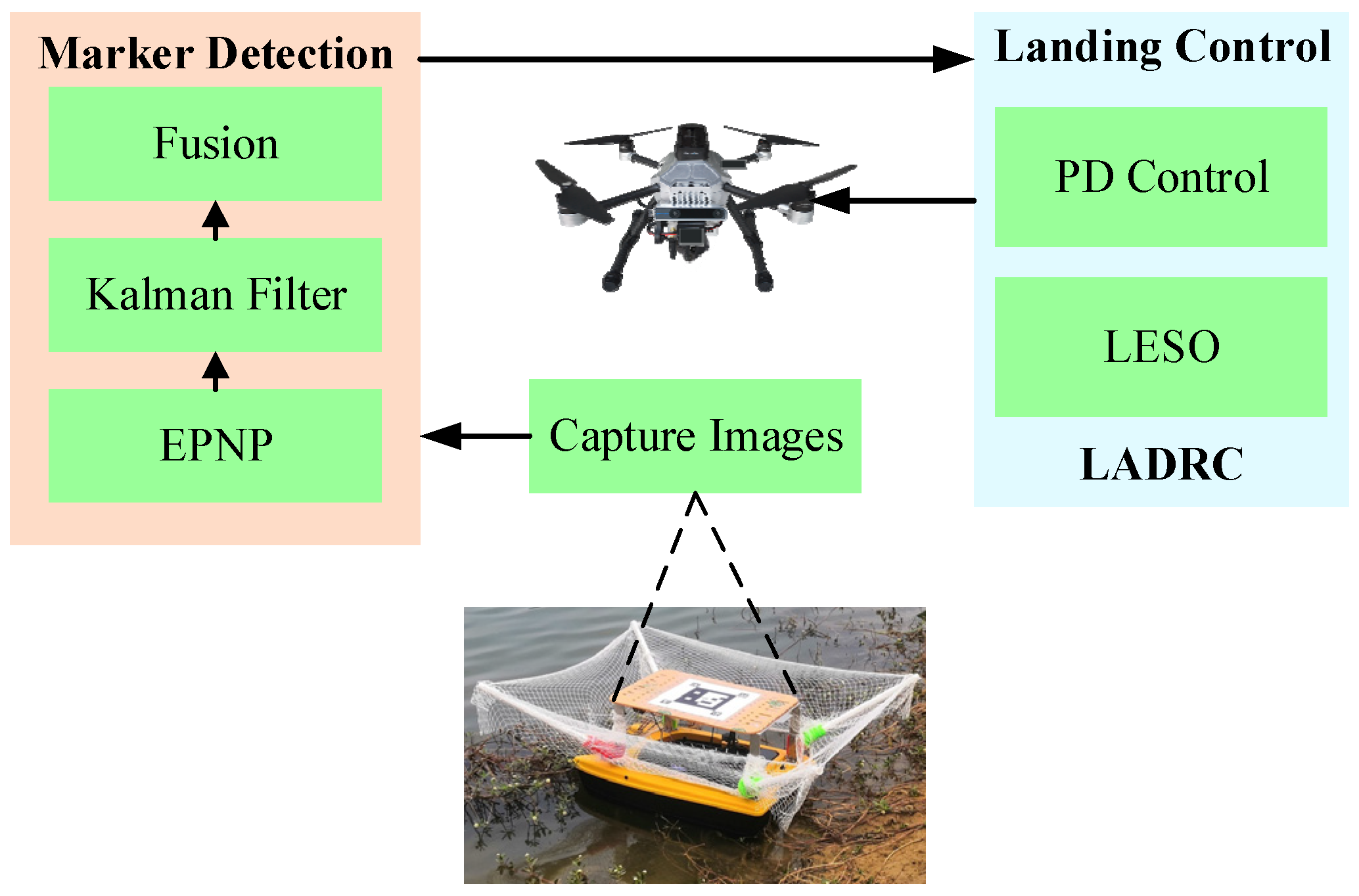
3. Landing Marker Detection
3.1. ArUco Recognition
3.2. Multi-Level Marker Fusion
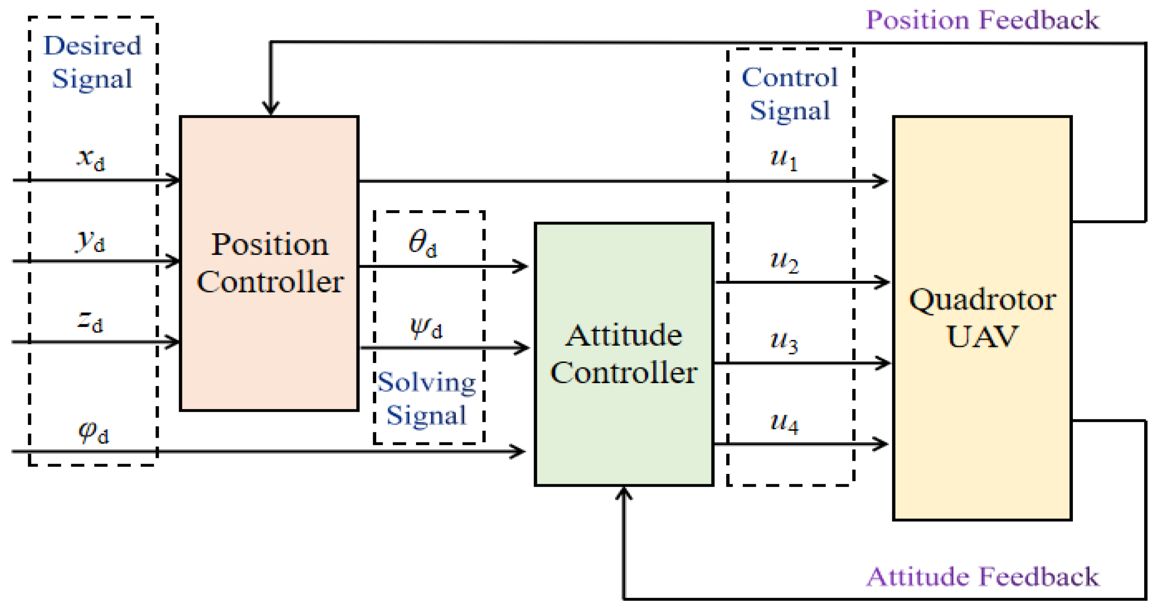
4. Landing Control Method
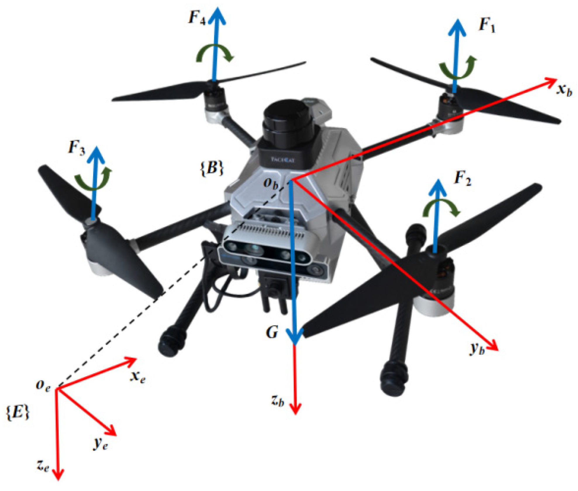
4.1. UAV Dynamics
4.2. Linear Active Disturbance Reject Control
5. Simulation and Experiment
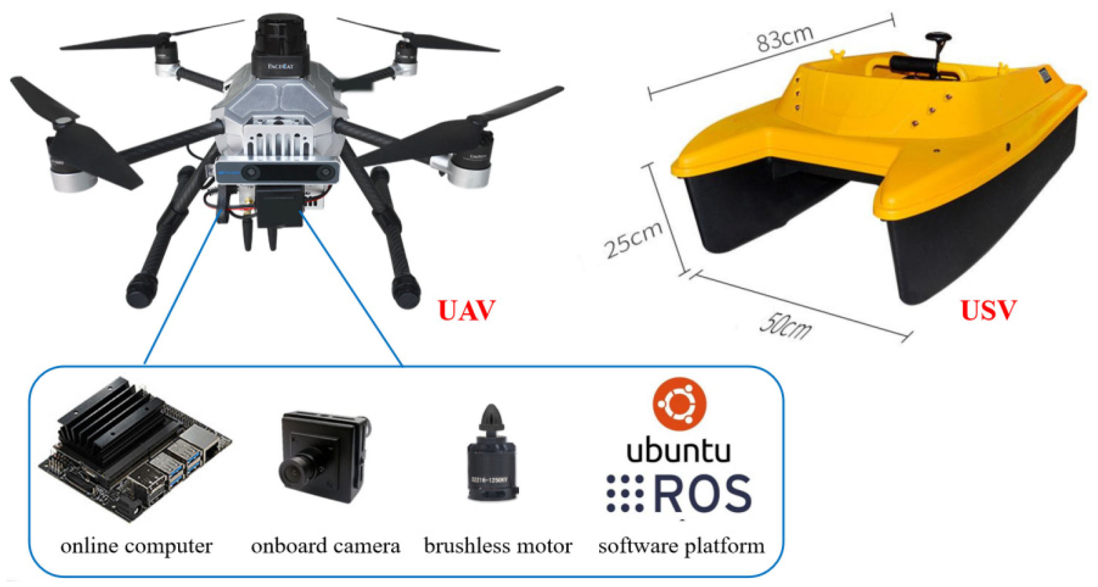
5.1. Platform
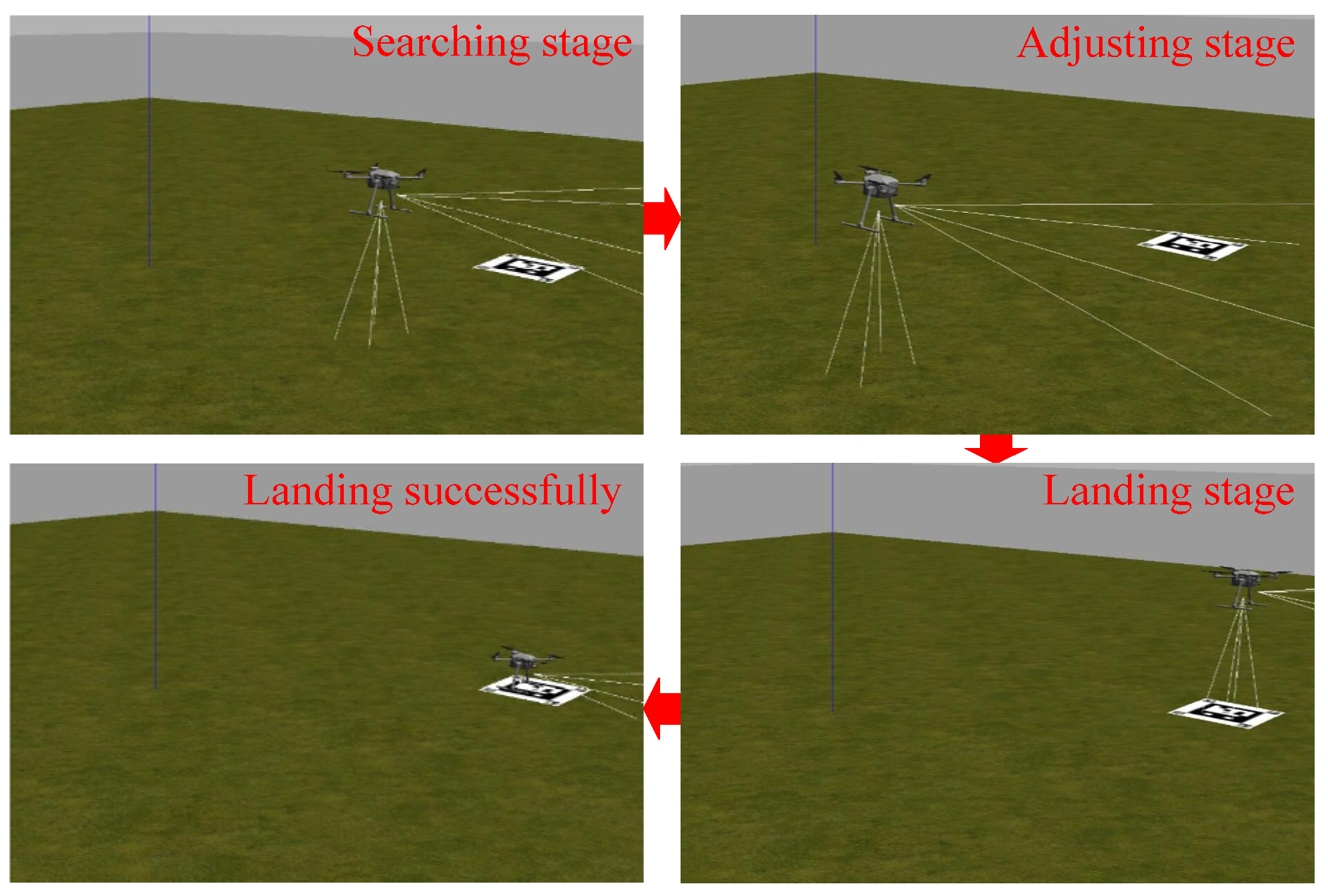
5.2. Simulation
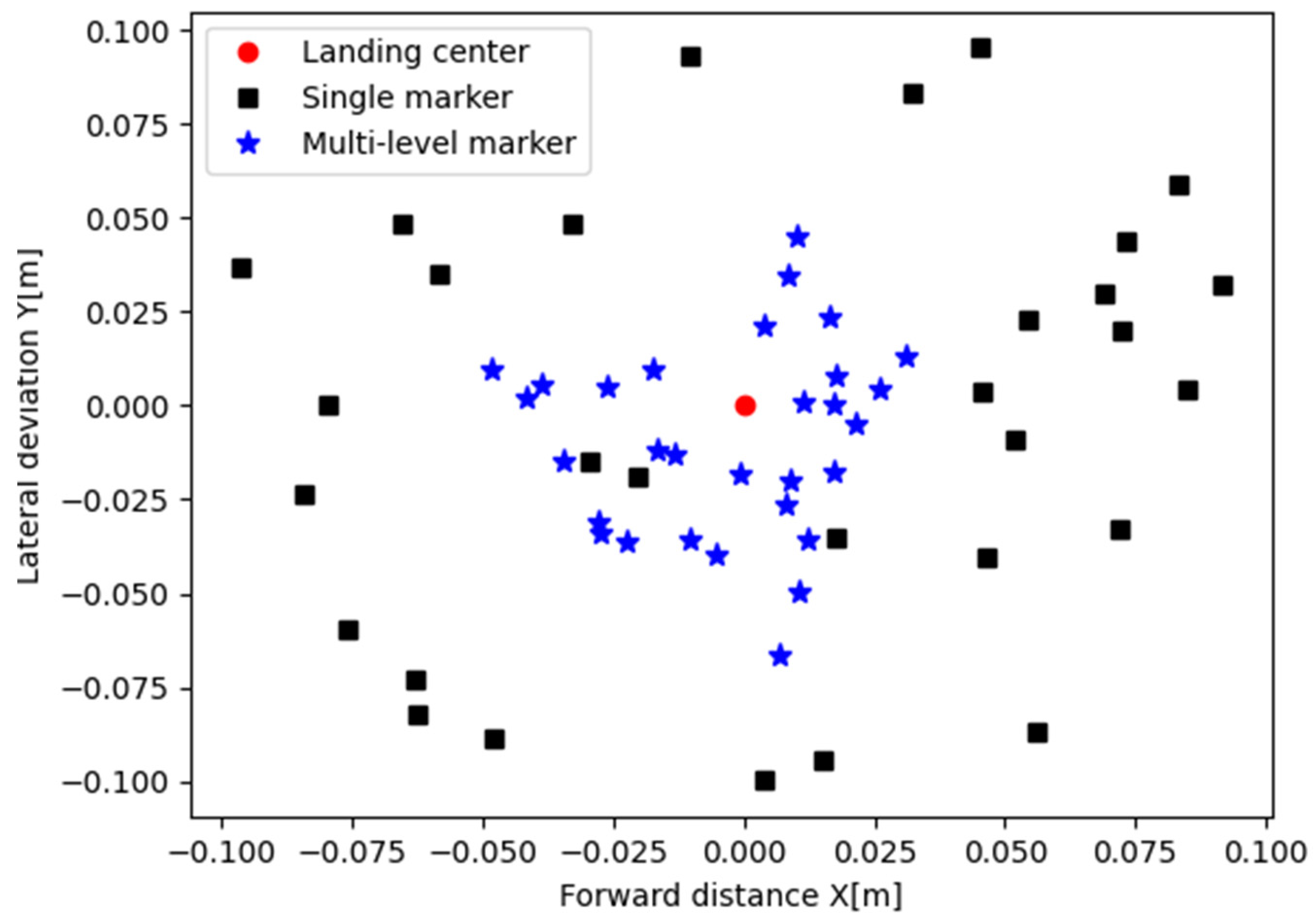
5.3. Ground Experiment
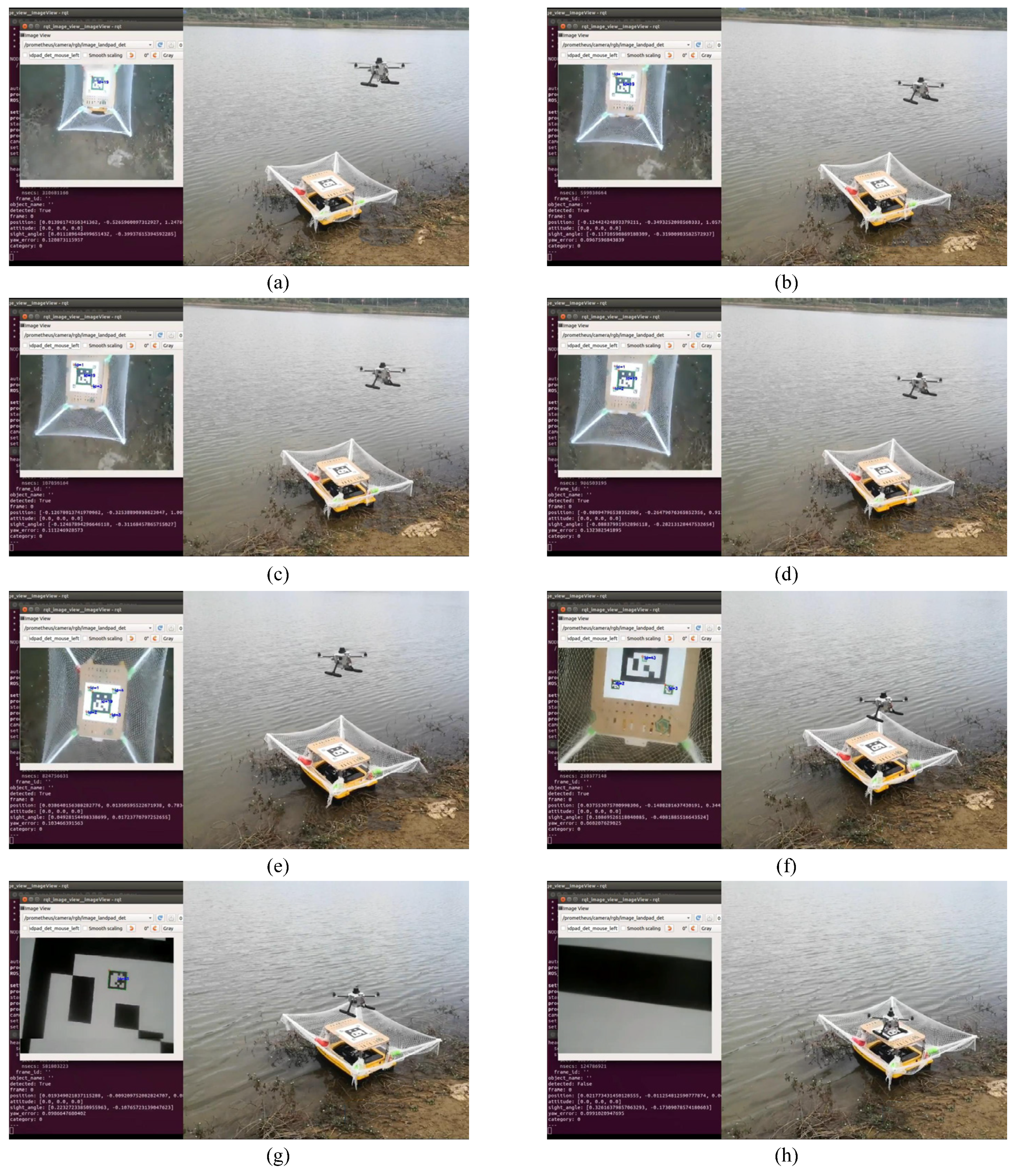
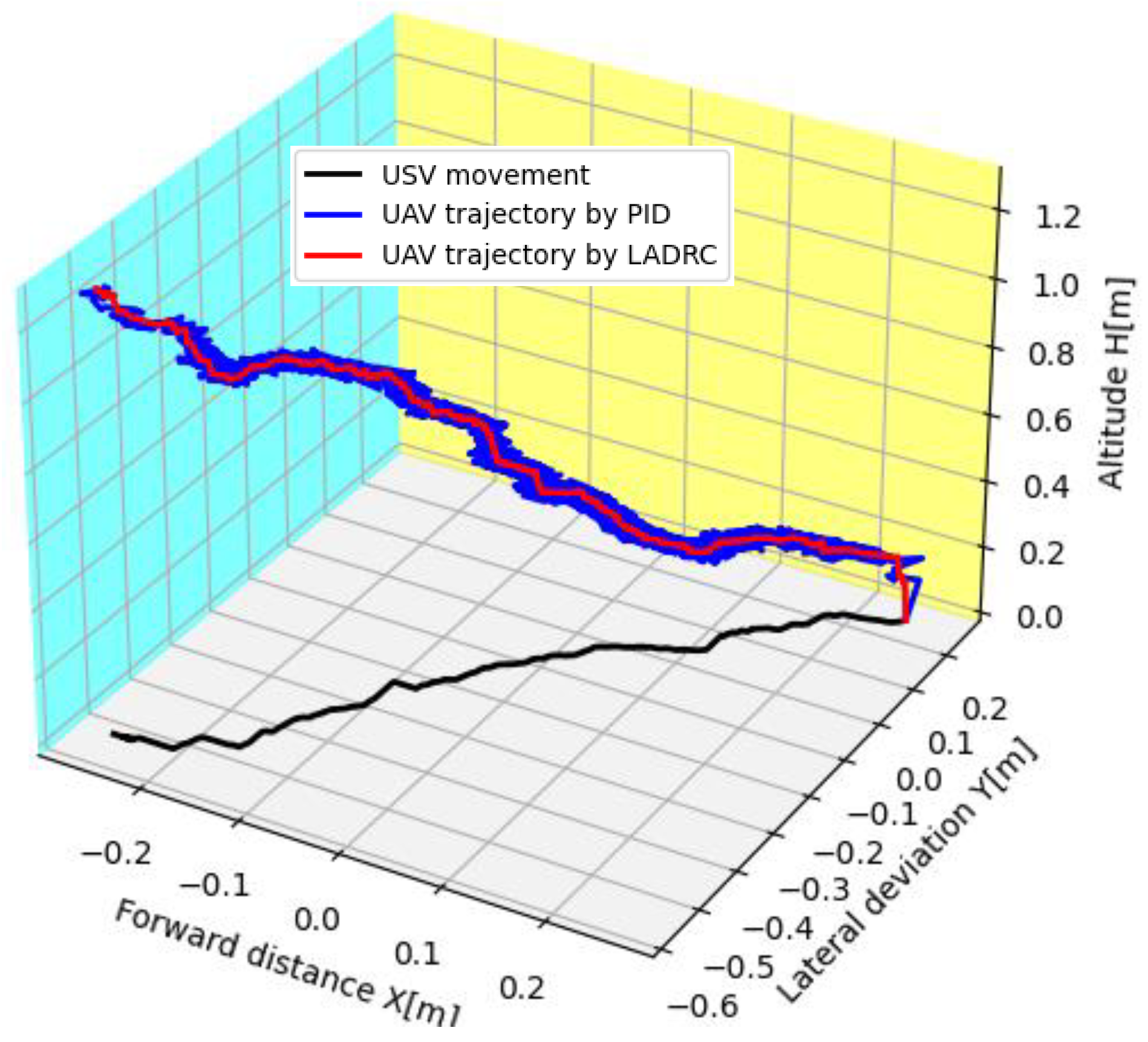
5.4. Surface Experiment
6. Conclusions and Future Work
Author Contributions
Funding
Institutional Review Board Statement
Informed Consent Statement
Data Availability Statement
Conflicts of Interest
References
- Cho, G.; Choi, J.; Bae, G.; Oh, H. Autonomous ship deck landing of a quadrotor UAV using feed-forward image-based visual servoing. Aerosp. Sci. Technol. 2022, 130, 107869. [Google Scholar] [CrossRef]
- Wang, Y.; Liu, W.; Liu, J.; Sun, C. Cooperative USV-UAV marine search and rescue with visual navigation and reinforcement learning-based control. ISA Trans. 2023, 137, 222–235. [Google Scholar] [CrossRef] [PubMed]
- Long, X.; Zimu, T.; Weiqi, G.; Haobo, L. Vision-Based Autonomous Landing for the UAV: A Review. Aerospace 2022, 9, 634. [Google Scholar]
- Lee, J.C.; Chen, C.C.; Shen, C.T.; Lai, Y.C. Landmark-Based Scale Estimation and Correction of Visual Inertial Odometry for VTOL UAVs in a GPS-Denied Environment. Sensors 2022, 22, 9654. [Google Scholar] [CrossRef] [PubMed]
- Wu, D.; Zhu, H.; Lan, Y. A Method for Designated Target Anti-Interference Tracking Combining YOLOv5 and SiamRPN for UAV Tracking and Landing Control. Remote Sens. 2022, 14, 2825. [Google Scholar] [CrossRef]
- Bouaiss, O.; Mechgoug, R.; Taleb-Ahmed, A. Visual soft landing of an autonomous quadrotor on a moving pad using a combined fuzzy velocity control with model predictive control. Signal Image Video Process. 2023, 17, 21–30. [Google Scholar] [CrossRef]
- Sonugür, G. A Review of quadrotor UAV: Control and SLAM methodologies ranging from conventional to innovative approaches. Robot. Auton. Syst. 2023, 161, 104342. [Google Scholar] [CrossRef]
- Rabah, M.; Haghbayan, H.; Immonen, E.; Plosila, J. An AI-in-Loop Fuzzy-Control Technique for UAV’s Stabilization and Landing. IEEE Access 2022, 10, 10119–101123. [Google Scholar] [CrossRef]
- Yuan, B.; Ma, W.; Wang, F. High Speed Safe Autonomous Landing Marker Tracking of Fixed Wing Drone Based on Deep Learning. IEEE Access 2022, 10, 3195286. [Google Scholar] [CrossRef]
- Alvika, G.; Mandeep, S.; Pedda, S.; Srikanth, S. Autonomous Quadcopter Landing on a Moving Target. Sensors 2022, 22, 1116. [Google Scholar]
- Lim, J.; Lee, T.; Pyo, S.; Lee, J.; Kim, J.; Lee, J. Hemispherical InfraRed (IR) Marker for Reliable Detection for Autonomous Landing on a Moving Ground Vehicle From Various Altitude Angles. IEEE/ASME Trans. Mechatron. 2022, 27, 485–492. [Google Scholar] [CrossRef]
- Wang, C.; Wang, J.; Wei, C.; Zhu, Y.; Yin, D.; Li, J. Vision-Based Deep Reinforcement Learning of UAV-UGV Collaborative Landing Policy Using Automatic Curriculum. Drones 2023, 7, 676. [Google Scholar] [CrossRef]
- Chen, C.; Chen, S.; Hu, G.; Chen, B.; Chen, P.; Su, K. An auto-landing strategy based on pan-tilt based visual servoing for unmanned aerial vehicle in GNSS-denied environments. Aerosp. Sci. Technol. 2021, 116, 106891. [Google Scholar] [CrossRef]
- El Gmili, N.; Mjahed, M.; El Kari, A.; Ayad, H. Particle swarm optimization based proportional-derivative parameters for unmanned tilt-rotor flight control and trajectory tracking. Automatika 2020, 61, 189–206. [Google Scholar] [CrossRef]
- Xu, J.; Zhang, K.; Zhang, D.; Wang, S.; Zhu, Q.; Gao, X. Composite anti-disturbance landing control scheme for recovery of carrier-based UAVs. Asian J. Control 2022, 24, 1744–1754. [Google Scholar] [CrossRef]
- Xia, K.; Lee, S.; Son, H. Adaptive control for multi-rotor UAVs autonomous ship landing with mission planning. Aerosp. Sci. Technol. 2020, 96, 105549. [Google Scholar] [CrossRef]
- Li, W.; Ge, Y.; Guan, Z.; Ye, G. Synchronized Motion-Based UAV-USV Cooperative Autonomous Landing. J. Mar. Sci. Eng. 2022, 10, 1214. [Google Scholar] [CrossRef]
- He, H.; Duan, H. A multi-strategy pigeon-inspired optimization approach to active disturbance rejection control parameters tuning for vertical take-off and landing fixed-wing UAV. Chin. J. Aeronaut. 2022, 35, 19–30. [Google Scholar] [CrossRef]
- Mathisen, S.; Gryte, K.; Gros, S.; Johansen, T.A. Precision Deep-Stall Landing of Fixed-Wing UAVs Using Nonlinear Model Predictive Control. J. Intell. Robot. Syst. 2021, 101, 24. [Google Scholar] [CrossRef]
- Chen, P.; Zhang, Y.; Wang, J.; Azar, A.T.; Hameed, I.A.; Ibraheem, I.K.; Kamal, N.A.; Abdulmajeed, F.A. Adaptive Internal Model Control Based on Parameter Adaptation. Electronics 2022, 11, 3842. [Google Scholar] [CrossRef]
- Latif, Z.; Shahzad, A.; Bhatti, A.I.; Whidborne, J.F.; Samar, R. Autonomous Landing of an UAV Using H∞ Based Model Predictive Control. Drones 2022, 6, 416. [Google Scholar] [CrossRef]
- Li, F.; Song, W.P.; Song, B.F.; Jiao, J. Dynamic Simulation and Conceptual Layout Study on a Quad-Plane in VTOL Mode in Wind Disturbance Environment. Int. J. Aerosp. Eng. 2022, 2022, 5867825. [Google Scholar] [CrossRef]
- Wang, L.; Jiang, X.; Wang, D.; Wang, L.; Tu, Z.; Ai, J. Research on Aerial Autonomous Docking and Landing Technology of Dual Multi-Rotor UAV. Sensors 2022, 22, 9066. [Google Scholar] [CrossRef]
- Aoki, N.; Ishigami, G. Autonomous tracking and landing of an unmanned aerial vehicle on a ground vehicle in rough terrain. Adv. Robot. 2023, 37, 344–355. [Google Scholar] [CrossRef]
- Sefidgar, M.; Landry, R., Jr. Landing System Development Based on Inverse Homography Range Camera Fusion (IHRCF). Sensors 2022, 22, 1870. [Google Scholar] [CrossRef] [PubMed]
- Arizaga, J.M.; Noriega, J.R.; Garcia-Delgado, L.A.; Castañeda, H. Adaptive Super Twisting Control of a Dual-rotor VTOL Flight System Under Model Uncertainties. Int. J. Control Autom. Syst. 2021, 19, 2251–2259. [Google Scholar] [CrossRef]
- Rabelo, M.F.; Brandão, A.S.; Sarcinelli-Filho, M. Landing a UAV on Static or Moving Platforms Using a Formation Controller. IEEE Syst. J. 2021, 15, 37–45. [Google Scholar] [CrossRef]
- Ghasemi, A.; Parivash, F.; Ebrahimian, S. Autonomous landing of a quadrotor on a moving platform using vision-based FOFPID control. Robotica 2022, 40, 1431–1449. [Google Scholar] [CrossRef]
- Wang, C.; Yan, J.; Li, W.; Shan, L.; Sun, L. Disturbances rejection optimization based on improved two-degree-of-freedom LADRC for permanent magnet synchronous motor systems. Def. Technol. 2023; in press. [Google Scholar] [CrossRef]


Disclaimer/Publisher’s Note: The statements, opinions and data contained in all publications are solely those of the individual author(s) and contributor(s) and not of MDPI and/or the editor(s). MDPI and/or the editor(s) disclaim responsibility for any injury to people or property resulting from any ideas, methods, instructions or products referred to in the content. |
© 2024 by the authors. Licensee MDPI, Basel, Switzerland. This article is an open access article distributed under the terms and conditions of the Creative Commons Attribution (CC BY) license (https://creativecommons.org/licenses/by/4.0/).
Share and Cite
Lv, M.; Fan, B.; Fang, J.; Wang, J. Autonomous Landing of Quadrotor Unmanned Aerial Vehicles Based on Multi-Level Marker and Linear Active Disturbance Reject Control. Sensors 2024, 24, 1645. https://doi.org/10.3390/s24051645
Lv M, Fan B, Fang J, Wang J. Autonomous Landing of Quadrotor Unmanned Aerial Vehicles Based on Multi-Level Marker and Linear Active Disturbance Reject Control. Sensors. 2024; 24(5):1645. https://doi.org/10.3390/s24051645
Chicago/Turabian StyleLv, Mingming, Bo Fan, Jiwen Fang, and Jia Wang. 2024. "Autonomous Landing of Quadrotor Unmanned Aerial Vehicles Based on Multi-Level Marker and Linear Active Disturbance Reject Control" Sensors 24, no. 5: 1645. https://doi.org/10.3390/s24051645
APA StyleLv, M., Fan, B., Fang, J., & Wang, J. (2024). Autonomous Landing of Quadrotor Unmanned Aerial Vehicles Based on Multi-Level Marker and Linear Active Disturbance Reject Control. Sensors, 24(5), 1645. https://doi.org/10.3390/s24051645