
Sensing of Continuum Robots: A Review

 ,
,  ,
,  ,
,  , , and
Abstract
1. Introduction
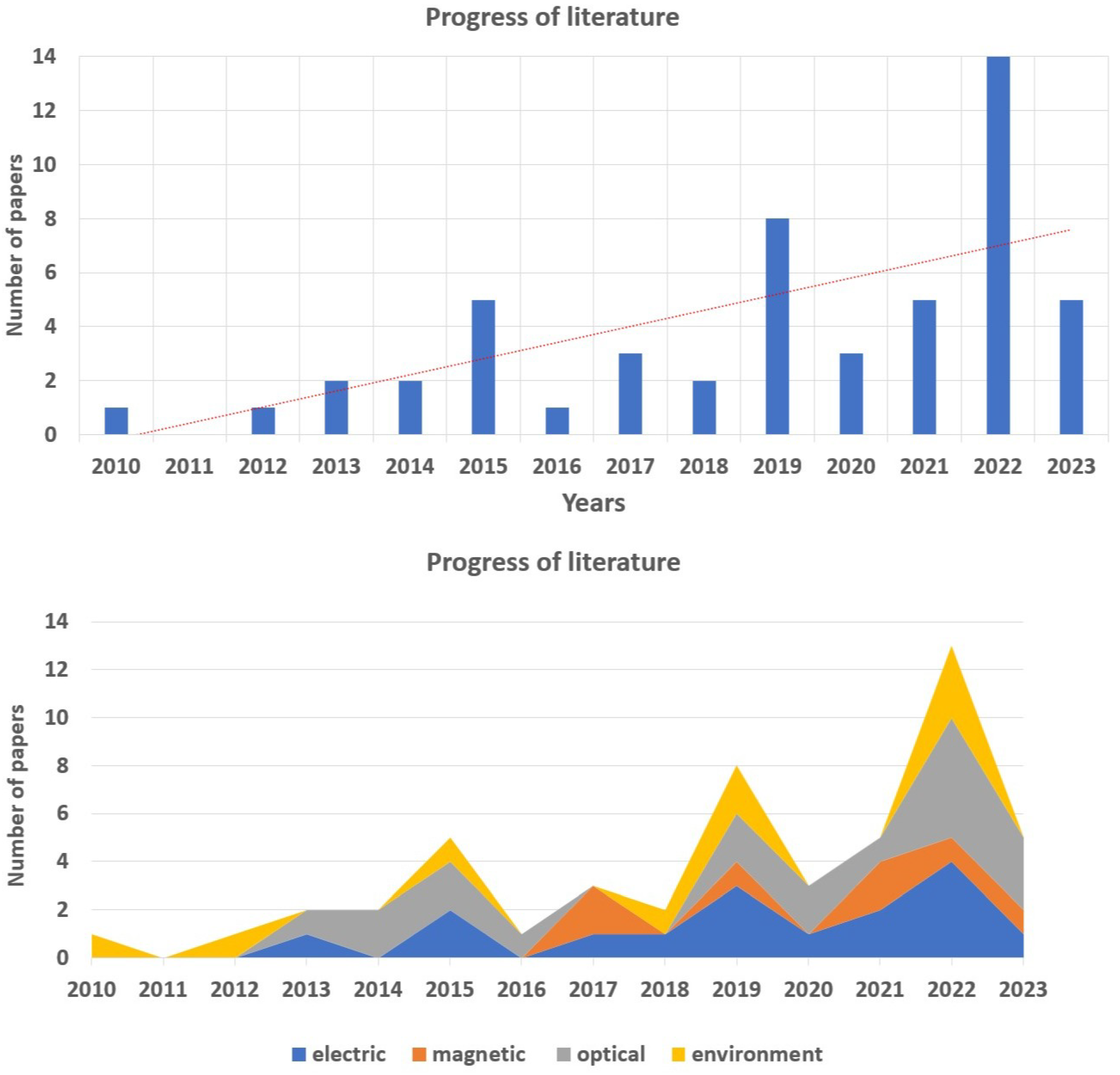
2. Methodology
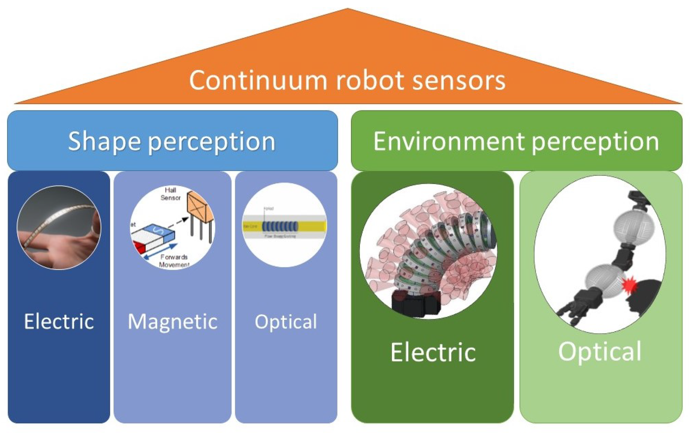
3. Classification
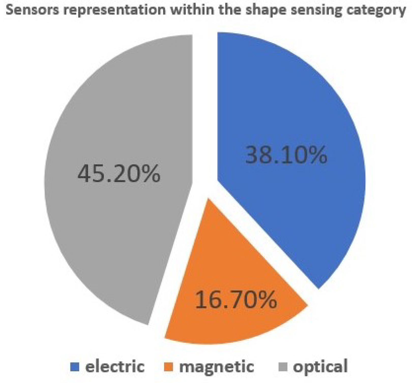
3.1. Shape Sensing
3.1.1. Electric Principle
3.1.2. Magnetic Principle
3.1.3. Optical Principle
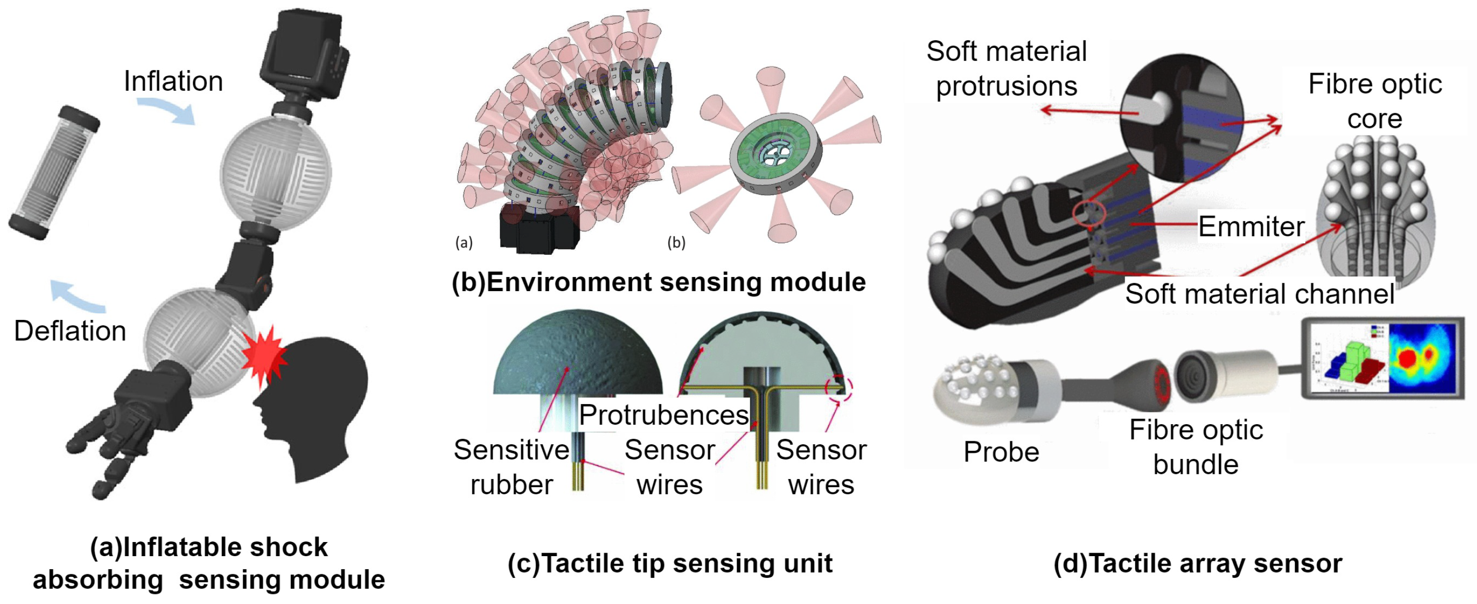
3.2. Environment Sensing
3.3. Applications
4. Conclusions
Author Contributions
Funding
Institutional Review Board Statement
Informed Consent Statement
Data Availability Statement
Acknowledgments
Conflicts of Interest
Abbreviations
| CR | continuum robot |
| IEEE | Institute of Electrical and Electronics Engineers |
| FBG | fiber Bragg grating |
| DTG | draw tower grating |
| WoS | Web of Science |
References
- Russo, M.; Sadati, S.M.H.; Dong, X.; Mohammad, A.; Walker, I.D.; Bergeles, C.; Xu, K.; Axinte, D.A. Continuum Robots: An Overview. Adv. Intell. Syst. 2023, 5, 2200367. [Google Scholar] [CrossRef]
- Walker, I.D. Continuous Backbone “Continuum” Robot Manipulators. Int. Sch. Res. Not. 2013, 2013, e726506. [Google Scholar] [CrossRef]
- Seleem, I.A.; El-Hussieny, H.; Ishii, H. Recent Developments of Actuation Mechanisms for Continuum Robots: A Review. Int. J. Control. Autom. Syst. 2023, 21, 1592–1609. [Google Scholar] [CrossRef]
- Wang, X.; Li, Y.; Kwok, K.W. A Survey for Machine Learning-Based Control of Continuum Robots. Front. Robot. AI 2021, 8, 730330. [Google Scholar] [CrossRef]
- Nguyen, T.D.; Burgner-Kahrs, J. A tendon-driven continuum robot with extensible sections. In Proceedings of the 2015 IEEE/RSJ International Conference on Intelligent Robots and Systems (IROS), Hamburg, Germany, 28 September–2 October 2015; pp. 2130–2135. [Google Scholar] [CrossRef]
- Geng, S.; Wang, Y.; Wang, C.; Kang, R. A Space Tendon-Driven Continuum Robot. In Proceedings of the Advances in Swarm Intelligence, ICSI 2018, Shanghai, China, 17–22 June 2018; Lecture Notes in Computer Science. pp. 25–35. [Google Scholar] [CrossRef]
- Bhattacherjee, S.; Chattopadhayay, S.; Rao, V.; Seth, S.; Mukherjee, S.; Sengupta, A.; Bhaumik, S. Kinematics and Teleoperation of Tendon Driven Continuum Robot. Procedia Comput. Sci. 2018, 133, 879–886. [Google Scholar] [CrossRef]
- Moradi Dalvand, M.; Nahavandi, S.; Howe, R.D. General Forward Kinematics for Tendon-Driven Continuum Robots. IEEE Access 2022, 10, 60330–60340. [Google Scholar] [CrossRef]
- Yoshikawa, D.; Shimizu, M.; Umedachi, T. A single motor-driven continuum robot that can be designed to deform into a complex shape with curvature distribution. Robomech. J. 2023, 10, 18. [Google Scholar] [CrossRef]
- Fellmann, C.; Burgner-Kahrs, J. Implications of trajectory generation strategies for tubular continuum robots. In Proceedings of the 2015 IEEE/RSJ International Conference on Intelligent Robots and Systems (IROS), Hamburg, Germany, 28 September–2 October 2015; pp. 202–208. [Google Scholar] [CrossRef]
- Burgner-Kahrs, J.; Rucker, D.C.; Choset, H. Continuum Robots for Medical Applications: A Survey. IEEE Trans. Robot. 2015, 31, 1261–1280. [Google Scholar] [CrossRef]
- Wu, L. Motion planning of continuum tubular robots based on features extracted from statistical atlas. In Proceedings of the 2015 IEEE/RSJ International Conference on Intelligent Robots and Systems (IROS), Hamburg, Germany, 28 September–2 October 2015. [Google Scholar] [CrossRef]
- Torres, L.G.; Kuntz, A.; Gilbert, H.B.; Swaney, P.J.; Hendrick, R.J.; Webster, R.J.; Alterovitz, R. A motion planning approach to automatic obstacle avoidance during concentric tube robot teleoperation. In Proceedings of the 2015 IEEE International Conference on Robotics and Automation (ICRA), Seattle, WA, USA, 25–30 May 2015; pp. 2361–2367. [Google Scholar] [CrossRef]
- Wu, L.; Song, S.; Wu, K.; Lim, C.M.; Ren, H. Development of a compact continuum tubular robotic system for nasopharyngeal biopsy. Med. Biol. Eng. Comput. 2017, 55, 403–417. [Google Scholar] [CrossRef]
- Kim, Y.; Parada, G.A.; Liu, S.; Zhao, X. Ferromagnetic soft continuum robots. Sci. Robot. 2019, 4, eaax7329. [Google Scholar] [CrossRef]
- Shoani, M.T.; Ribuan, M.N.; Faudzi, A.A.M. A Novel Approach for Reducing Actuators in Soft Continuum Robots and Manipulators. In Proceedings of the Robot Intelligence Technology and Applications 6, Daejeon, Republic of Korea, 7–9 December 2022; pp. 181–190. [Google Scholar] [CrossRef]
- Lu, J.; Liu, F.; Girerd, C.; Yip, M.C. Image-based Pose Estimation and Shape Reconstruction for Robot Manipulators and Soft, Continuum Robots via Differentiable Rendering: Technical report. arXiv 2023, arXiv:2302.14039. [Google Scholar] [CrossRef]
- Fischer, O.; Toshimitsu, Y.; Kazemipour, A.; Katzschmann, R.K. Dynamic Task Space Control Enables Soft Manipulators to Perform Real-World Tasks. Adv. Intell. Syst. 2023, 5, 2200024. [Google Scholar] [CrossRef]
- El-Atab, N.; Mishra, R.B.; Al-Modaf, F.; Joharji, L.; Alsharif, A.A.; Alamoudi, H.; Diaz, M.; Qaiser, N.; Hussain, M.M. Soft Actuators for Soft Robotic Applications: A Review. Adv. Intell. Syst. 2020, 2, 2000128. [Google Scholar] [CrossRef]
- So, J.; Kim, U.; Kim, Y.B.; Seok, D.Y.; Yang, S.Y.; Kim, K.; Park, J.H.; Hwang, S.T.; Gong, Y.J.; Choi, H.R. Shape Estimation of Soft Manipulator Using Stretchable Sensor. Cyborg Bionic Syst. 2021, 2021, 9843894. [Google Scholar] [CrossRef]
- Chen, Y.; Oliveira, J.M.; Hunter, I.W. Two-axis bend sensor design, kinematics and control for a continuum robotic endoscope. In Proceedings of the 2013 IEEE International Conference on Robotics and Automation, Karlsruhe, Germany, 6–10 May 2013; pp. 704–710. [Google Scholar] [CrossRef]
- Wurdemann, H.A.; Sareh, S.; Shafti, A.; Noh, Y.; Faragasso, A.; Chathuranga, D.S.; Liu, H.; Hirai, S.; Althoefer, K. Embedded electro-conductive yarn for shape sensing of soft robotic manipulators. In Proceedings of the 2015 37th Annual International Conference of the IEEE Engineering in Medicine and Biology Society (EMBC), Milan, Italy, 25–29 August 2015; pp. 8026–8029. [Google Scholar] [CrossRef]
- Wurdemann, H.; Sareh, S.; Shafti, A.; Noh, Y.; Faragasso, A.; Liu, H.; Althoefer, K.; Chathuranga, D.; Hirai, S. Integrated soft bending sensor for soft robotic manipulators. In Proceedings of the Joint Workshop on Computer/Robot Assisted Surgery, Milan, Italy, 25–29 August 2015. [Google Scholar]
- Visentin, F.; Fiorini, P. A flexible sensor for soft-bodied robots based on electrical impedance tomography. In Proceedings of the 2018 IEEE International Conference on Soft Robotics (RoboSoft), Livorno, Italy, 24–28 April 2018; pp. 158–163. [Google Scholar] [CrossRef]
- Park, M.; Ohm, Y.; Kim, D.; Park, Y.L. Multi-Material Soft Strain Sensors with High Gauge Factors for Proprioceptive Sensing of Soft Bending Actuators. In Proceedings of the 2019 2nd IEEE International Conference on Soft Robotics (RoboSoft), Seoul, Republic of Korea, 14–18 April 2019; pp. 384–390. [Google Scholar] [CrossRef]
- Avery, J.; Runciman, M.; Darzi, A.; Mylonas, G.P. Shape Sensing of Variable Stiffness Soft Robots using Electrical Impedance Tomography. In Proceedings of the 2019 International Conference on Robotics and Automation (ICRA), Montreal, QC, Canada, 20–24 May 2019; pp. 9066–9072. [Google Scholar] [CrossRef]
- Galeta, E.V.; Ahmed, S.; Parque, V.; El-Hussieny, H. Design and Characterization of an e-Textile Sensorfor Shape Sensing of Soft Continuum Robots. In Proceedings of the 2023 62nd Annual Conference of the Society of Instrument and Control Engineers of Japan (SICE), Tsu, Japan, 6–9 September 2023; pp. 1110–1115. [Google Scholar]
- Gerboni, G.; Diodato, A.; Ciuti, G.; Cianchetti, M.; Menciassi, A. Feedback Control of Soft Robot Actuators via Commercial Flex Bend Sensors. IEEE ASME Trans. Mechatronics 2017, 22, 1881–1888. [Google Scholar] [CrossRef]
- Hainsworth, T.; Smith, L.; Alexander, S.; MacCurdy, R. A Fabrication Free, 3D Printed, Multi-Material, Self-Sensing Soft Actuator. IEEE Robot. Autom. Lett. 2020, 5, 4118–4125. [Google Scholar] [CrossRef]
- Johnson, W.R.; Agrawala, A.; Huang, X.; Booth, J.; Kramer-Bottiglio, R. Sensor Tendons for Soft Robot Shape Estimation. In Proceedings of the 2022 IEEE Sensors, Dalas, TX, USA, 30 October–2 November 2022; pp. 1–4. [Google Scholar] [CrossRef]
- Sahu, S.K.; Tamadon, I.; Rosa, B.; Renaud, P.; Menciassi, A. A Spring-Based Inductive Sensor for Soft and Flexible Robots. IEEE Sens. J. 2022, 22, 19931–19940. [Google Scholar] [CrossRef]
- Alatorre, D.; Axinte, D.; Rabani, A. Continuum Robot Proprioception: The Ionic Liquid Approach. IEEE Trans. Robot. 2022, 38, 526–535. [Google Scholar] [CrossRef]
- Hughes, J.; Stella, F.; Santina, C.D.; Rus, D. Sensing Soft Robot Shape Using IMUs: An Experimental Investigation. In Proceedings of the International Symposium of Experimental Robotics, La Valletta, Malta, 9–12 November 2020; pp. 543–552. [Google Scholar] [CrossRef]
- Felt, W.; Telleria, M.J.; Allen, T.F.; Hein, G.; Pompa, J.B.; Albert, K.; Remy, C.D. An inductance-based sensing system for bellows-driven continuum joints in soft robots. Auton. Robot. 2019, 43, 435–448. [Google Scholar] [CrossRef]
- Yan, H.; Wang, Y.; Shen, W.; Li, F.; Gao, G.; Zheng, T.; Xu, Z.; Qian, S.; Chen, C.Y.; Zhang, C.; et al. Cable-Driven Continuum Robot Perception Using Skin-Like Hydrogel Sensors. Adv. Funct. Mater. 2022, 32, 2203241. [Google Scholar] [CrossRef]
- Wang, J.; Lu, Y.; Zhang, C.; Song, S.; Meng, M.Q.H. Pilot study on shape sensing for continuum tubular robot with multi-magnet tracking algorithm. In Proceedings of the 2017 IEEE International Conference on Robotics and Biomimetics (ROBIO), Macao, China, 5–8 December 2017; pp. 1165–1170. [Google Scholar] [CrossRef]
- Zhang, C.; Lu, Y.; Song, S.; Meng, M.Q.H. Shape tracking and navigation for continuum surgical robot based on magnetic tracking. In Proceedings of the 2017 IEEE International Conference on Information and Automation (ICIA), Macao, China, 18–20 July 2017; pp. 1143–1149. [Google Scholar] [CrossRef]
- Jeon, J.; Kim, C. Shape Sensor Using Magnetic Induction with Frequency Sweeping for Medical Catheters. In Proceedings of the 2021 IEEE International Conference on Robotics and Automation (ICRA), Xi’an, China, 30 May–5 June 2021; pp. 7137–7143. [Google Scholar] [CrossRef]
- Song, S.; Ge, H.; Wang, J.; Meng, M.Q.H. Real-Time Multi-Object Magnetic Tracking for Multi-Arm Continuum Robots. IEEE Trans. Instrum. Meas. 2021, 70, 1–9. [Google Scholar] [CrossRef]
- Guo, H.; Ju, F.; Cao, Y.; Qi, F.; Bai, D.; Wang, Y.; Chen, B. Continuum robot shape estimation using permanent magnets and magnetic sensors. Sens. Actuators A Phys. 2019, 285, 519–530. [Google Scholar] [CrossRef]
- Baaij, T.; Holkenborg, M.K.; Stölzle, M.; Tuin, D.v.d.; Naaktgeboren, J.; Babuška, R.; Santina, C.D. Learning 3D shape proprioception for continuum soft robots with multiple magnetic sensors. Soft Matter 2022, 19, 44–56. [Google Scholar] [CrossRef]
- Costa, C.F.R.; Reis, J.C.P. End-Point Position Estimation of a Soft Continuum Manipulator Using Embedded Linear Magnetic Encoders. Sensors 2023, 23, 1647. [Google Scholar] [CrossRef]
- Searle, T.C.; Althoefer, K.; Seneviratne, L.; Liu, H. An optical curvature sensor for flexible manipulators. In Proceedings of the 2013 IEEE International Conference on Robotics and Automation, Karlsruhe, Germany, 6–10 May 2013; pp. 4415–4420. [Google Scholar] [CrossRef]
- Kim, B.; Ha, J.; Park, F.C.; Dupont, P.E. Optimizing curvature sensor placement for fast, accurate shape sensing of continuum robots. In Proceedings of the 2014 IEEE International Conference on Robotics and Automation (ICRA), Hong Kong, China, 31 May–7 June 2014; pp. 5374–5379. [Google Scholar] [CrossRef]
- Ryu, S.C.; Dupont, P.E. FBG-based shape sensing tubes for continuum robots. In Proceedings of the 2014 IEEE International Conference on Robotics and Automation (ICRA), Hong Kong, China, 31 May–7 June 2014; pp. 3531–3537. [Google Scholar] [CrossRef]
- Liu, H.; Farvardin, A.; Pedram, S.A.; Iordachita, I.; Taylor, R.H.; Armand, M. Large deflection shape sensing of a continuum manipulator for minimally-invasive surgery. In Proceedings of the 2015 IEEE International Conference on Robotics and Automation (ICRA), Seattle, WA, USA, 26–30 May 2015; pp. 201–206. [Google Scholar] [CrossRef]
- Sareh, S.; Noh, Y.; Ranzani, T.; Wurdemann, H.; Liu, H.; Althoefer, K. A 7.5 mm Steiner chain fibre-optic system for multi-segment flex sensing. In Proceedings of the IEEE/RSJ International Conference on Intelligent Robots and Systems (IROS), Hamburg Germany, 28 September–2 October 2015. [Google Scholar] [CrossRef]
- Lu, Y.; Chen, W.; Chen, Z.; Zhou, J.; Liu, Y. FBG-Based Variable-Length Estimation for Shape Sensing of Extensible Soft Robotic Manipulators. In Proceedings of the 2022 IEEE/RSJ International Conference on Intelligent Robots and Systems (IROS), Kyoto, Japan, 23–27 October 2022; pp. 1–8. [Google Scholar] [CrossRef]
- Xu, R.; Yurkewich, A.; Patel, R.V. Curvature, Torsion, and Force Sensing in Continuum Robots Using Helically Wrapped FBG Sensors. IEEE Robot. Autom. Lett. 2016, 1, 1052–1059. [Google Scholar] [CrossRef]
- Rahman, N.; Deaton, N.; Sheng, J.; Cheng, S.S.; Desai, J. Modular FBG Bending Sensor for Continuum Neurosurgical Robot. IEEE Robot. Autom. Lett. 2019, 4, 1424–1430. [Google Scholar] [CrossRef]
- Li, J.; Zhang, F.; Yang, Z.; Jiang, Z.; Wang, Z.; Liu, H. Shape Sensing for Continuum Robots by Capturing Passive Tendon Displacements with Image Sensors. IEEE Robot. Autom. Lett. 2022, 7, 3130–3137. [Google Scholar] [CrossRef]
- Shentu, C.; Li, E.; Chen, C.; Dewi, P.T.; Lindell, D.B.; Burgner-Kahrs, J. MoSS: Monocular Shape Sensing for Continuum Robots: Technical report. arXiv 2023, arXiv:2303.00891. [Google Scholar] [CrossRef]
- Chitalia, Y.; Deaton, N.J.; Jeong, S.; Rahman, N.; Desai, J.P. Towards FBG-Based Shape Sensing for Micro-Scale and Meso-Scale Continuum Robots with Large Deflection. IEEE Robot. Autom. Lett. 2020, 5, 1712–1719. [Google Scholar] [CrossRef]
- Cao, Y.; Liu, Z.; Yu, H.; Hong, W.; Xie, L. Spatial Shape Sensing of a Multisection Continuum Robot with Integrated DTG Sensor for Maxillary Sinus Surgery. IEEE ASME Trans. Mechatronics 2023, 28, 715–725. [Google Scholar] [CrossRef]
- Cao, Y.; Feng, F.; Liu, Z.; Xie, L. Closed-loop Trajectory Tracking Control of a Cable-driven Continuum Robot with Integrated DTG Sensor Feedback. J. Mech. Robot. 2022, 14, 1–21. [Google Scholar] [CrossRef]
- Galloway, K.C.; Chen, Y.; Templeton, E.; Rife, B.; Godage, I.S.; Barth, E.J. Fiber Optic Shape Sensing for Soft Robotics. Soft Robot. 2019, 6, 671–684. [Google Scholar] [CrossRef] [PubMed]
- Qi, F.; Chen, B.; She, S.; Gao, S. Shape sensing and feedback control of the catheter robot for interventional surgery. Ind. Robot. Int. J. Robot. Res. Appl. 2020, 48, 259–269. [Google Scholar] [CrossRef]
- He, Y.; Gao, L.; Bai, Y.; Zhu, H.; Sun, G.; Zhu, L.; Xu, H. Stretchable optical fibre sensor for soft surgical robot shape reconstruction. Opt. Appl. 2021, 51, 589–604. [Google Scholar] [CrossRef]
- Hou, L.; Tam, S.; Zhao, X.; Tao, B. Shape Reconstruction Method for Continuum Robot Using FBG Sensors. In Proceedings of the Intelligent Robotics and Applications, Harbin, China, 1–3 August 2022; pp. 388–395. [Google Scholar] [CrossRef]
- Li, D.; Wang, C.; Guo, W.; Wang, Z.; Zhang, Z.; Liu, H. Shape Sensing for Single-Port Continuum Surgical Robot Using Few Multicore Fiber Bragg Grating Sensors. J. Shanghai Jiaotong Univ. Sci. 2023, 28, 312–322. [Google Scholar] [CrossRef]
- Dragone, D.; Donadio, F.F.; Mirabelli, C.; Cosentino, C.; Amato, F.; Zaffino, P.; Spadea, M.F.; La Torre, D.; Merola, A. Design and Experimental Validation of a 3D-Printed Embedded-Sensing Continuum Robot for Neurosurgery. Micromachines 2023, 14, 1743. [Google Scholar] [CrossRef]
- Ha, X.T.; Wu, D.; Lai, C.F.; Ourak, M.; Borghesan, G.; Menciassi, A.; Poorten, E.V. Contact Localization of Continuum and Flexible Robot Using Data-Driven Approach. IEEE Robot. Autom. Lett. 2022, 7, 6910–6917. [Google Scholar] [CrossRef]
- Kim, T.; Yoon, S.J.; Park, Y.L. Soft Inflatable Sensing Modules for Safe and Interactive Robots. IEEE Robot. Autom. Lett. 2018, 3, 3216–3223. [Google Scholar] [CrossRef]
- Abah, C.; Orekhov, A.L.; Johnston, G.L.H.; Simaan, N. A Multi-Modal Sensor Array for Human–Robot Interaction and Confined Spaces Exploration Using Continuum Robots. IEEE Sens. J. 2022, 22, 3585–3594. [Google Scholar] [CrossRef] [PubMed]
- Bajo, A.; Simaan, N. Kinematics-Based Detection and Localization of Contacts Along Multisegment Continuum Robots. IEEE Trans. Robot. 2012, 28, 291–302. [Google Scholar] [CrossRef]
- Back, J.; Dasgupta, P.; Seneviratne, L.; Althoefer, K.; Liu, H. Feasibility study- novel optical soft tactile array sensing for minimally invasive surgery. In Proceedings of the 2015 IEEE/RSJ International Conference on Intelligent Robots and Systems (IROS), Hamburg, Germany, 28 September–2 October 2015; pp. 1528–1533. [Google Scholar] [CrossRef]
- Abah, C.; Orekhov, A.L.; Johnston, G.L.; Yin, P.; Choset, H.; Simaan, N. A Multi-modal Sensor Array for Safe Human-Robot Interaction and Mapping. In Proceedings of the 2019 International Conference on Robotics and Automation (ICRA), Montreal, QC, Canada, 20–24 May 2019; pp. 3768–3774. [Google Scholar] [CrossRef]
- Bajo, A.; Simaan, N. Finding lost wrenches: Using continuum robots for contact detection and estimation of contact location. In Proceedings of the 2010 IEEE International Conference on Robotics and Automation, Anchorage, AK, USA, 3–7 May 2010; pp. 3666–3673. [Google Scholar] [CrossRef]
- Yaming, W.; Ju, F.; Cao, Y.; Yun, Y.; Wang, Y.; Bai, D.; Chen, B. An aero-engine inspection continuum robot with tactile sensor based on EIT for exploration and navigation in unknown environment. In Proceedings of the 2019 IEEE/ASME International Conference on Advanced Intelligent Mechatronics (AIM), Hong Kong, China, 8–12 July 2019; pp. 1157–1162. [Google Scholar] [CrossRef]
- Yaming, W.; Ju, F.; Yun, Y.; Yao, J.; Wang, Y.; Hao, G.; Bai, C. An inspection continuum robot with tactile sensor based on electrical impedance tomography for exploration and navigation in unknown environment. Ind. Robot. Int. J. Robot. Res. Appl. 2019. ahead-of-print. [Google Scholar] [CrossRef]
- Yamauchi, Y.; Ambe, Y.; Nagano, H.; Konyo, M.; Bando, Y.; Ito, E.; Arnold, S.; Yamazaki, K.; Itoyama, K.; Okatani, T.; et al. Development of a continuum robot enhanced with distributed sensors for search and rescue. Robomech. J. 2022, 9, 8. [Google Scholar] [CrossRef]
- Saraf, A.; Moon, S.; Madotto, A. A Survey of Datasets, Applications, and Models for IMU Sensor Signals. In Proceedings of the 2023 IEEE International Conference on Acoustics, Speech, and Signal Processing Workshops (ICASSPW), Rhodes Island, Greece, 4–10 June 2023; pp. 1–5. [Google Scholar] [CrossRef]
- Jain, S.; Agrawal, U.; Kumar, A.; Agrawal, A.; Yadav, G.S. Simultaneous Localization and Mapping for Autonomous Robot Navigation. In Proceedings of the 2021 International Conference on Communication, Control and Information Sciences (ICCISc), Idukki, India, 16–18 June 2021; Volume 1, pp. 1–5. [Google Scholar] [CrossRef]
- Ballard, D. Modular Learning in Neural Networks. In Proceedings of the AAAI-87, Seattle, WA, USA, 13–17 July 1987; pp. 279–284. [Google Scholar]


| Perception | Sensing Technology | Paper | Publisher | Type of Paper |
|---|---|---|---|---|
| Shape | [20] | AAAS | Journal | |
| [21,22,23,24,25,26,27] | IEEE | Conference | ||
| Electric | [28,29,30,31,32] | IEEE | Journal | |
| [33] | Springer | Conference | ||
| [34] | Springer | Journal | ||
| [35] | Wiley | Journal | ||
| [36,37,38] | IEEE | Conference | ||
| [39] | IEEE | Journal | ||
| Magnetic | [40] | Elsevier | Journal | |
| [41] | RCS(WoS) | Journal | ||
| [42] | MDPI | Journal | ||
| [43,44,45,46,47,48] | IEEE | Conference | ||
| [49,50,51,52,53] | IEEE | Journal | ||
| [54,55] | IEEE/ASME(WoS) | Journal | ||
| [56] | Mary Ann Liebert(WoS) | Journal | ||
| Optical | [57] | EMERALD(WoS) | Journal | |
| [58] | Wroclaw univ science technology (WoS) | Journal | ||
| [59] | Springer | Conference | ||
| [60] | Springer | Journal | ||
| [61] | MDPI | Journal | ||
| Environment | [62,63,64,65] | IEEE | Journal | |
| [66,67,68,69] | IEEE | Conference | ||
| - | [70] | EMERALD(WoS) | Journal | |
| [71] | Springer | Journal |
Disclaimer/Publisher’s Note: The statements, opinions and data contained in all publications are solely those of the individual author(s) and contributor(s) and not of MDPI and/or the editor(s). MDPI and/or the editor(s) disclaim responsibility for any injury to people or property resulting from any ideas, methods, instructions or products referred to in the content. |
© 2024 by the authors. Licensee MDPI, Basel, Switzerland. This article is an open access article distributed under the terms and conditions of the Creative Commons Attribution (CC BY) license (https://creativecommons.org/licenses/by/4.0/).
Share and Cite
Sincak, P.J.; Prada, E.; Miková, Ľ.; Mykhailyshyn, R.; Varga, M.; Merva, T.; Virgala, I. Sensing of Continuum Robots: A Review. Sensors 2024, 24, 1311. https://doi.org/10.3390/s24041311
Sincak PJ, Prada E, Miková Ľ, Mykhailyshyn R, Varga M, Merva T, Virgala I. Sensing of Continuum Robots: A Review. Sensors. 2024; 24(4):1311. https://doi.org/10.3390/s24041311
Chicago/Turabian StyleSincak, Peter Jan, Erik Prada, Ľubica Miková, Roman Mykhailyshyn, Martin Varga, Tomas Merva, and Ivan Virgala. 2024. "Sensing of Continuum Robots: A Review" Sensors 24, no. 4: 1311. https://doi.org/10.3390/s24041311
APA StyleSincak, P. J., Prada, E., Miková, Ľ., Mykhailyshyn, R., Varga, M., Merva, T., & Virgala, I. (2024). Sensing of Continuum Robots: A Review. Sensors, 24(4), 1311. https://doi.org/10.3390/s24041311