


Polymer Waveguide Sensor Based on Evanescent Bragg Grating for Lab-on-a-Chip Applications

 ,
,  and
and 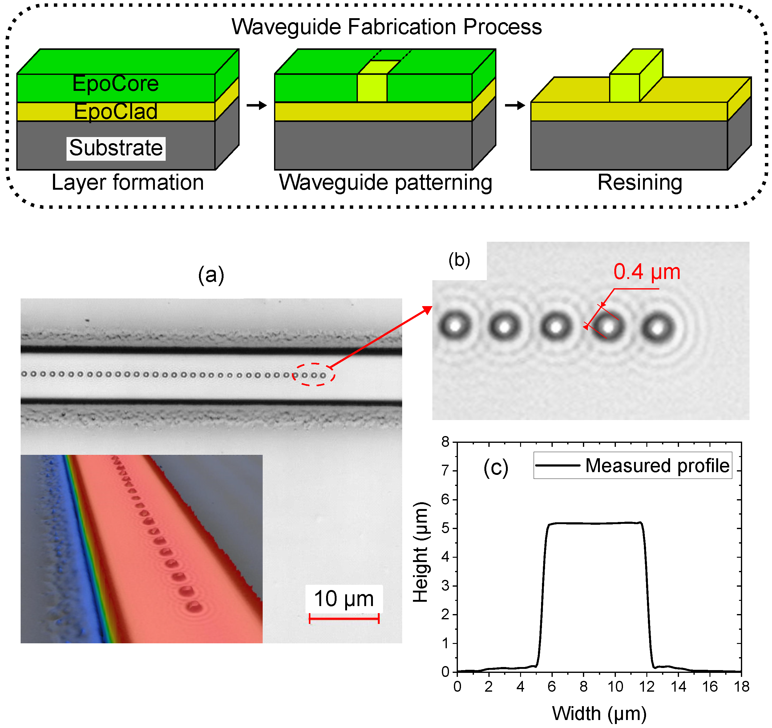
Abstract
1. Introduction
2. Materials and Methods
2.1. Waveguide Fabrication
2.2. Bragg Grating Inscription
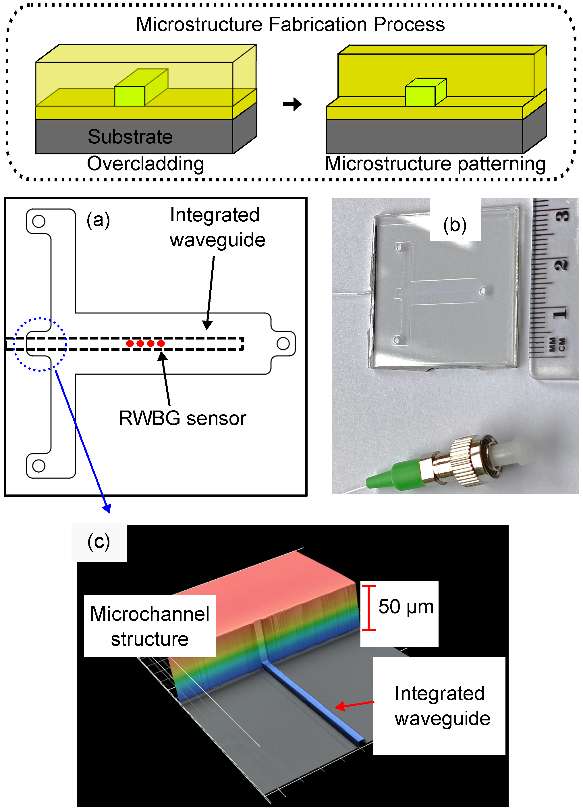
2.3. Sensor Integration in LOC Concept
2.4. Functional Coating for Hydrogen Detection
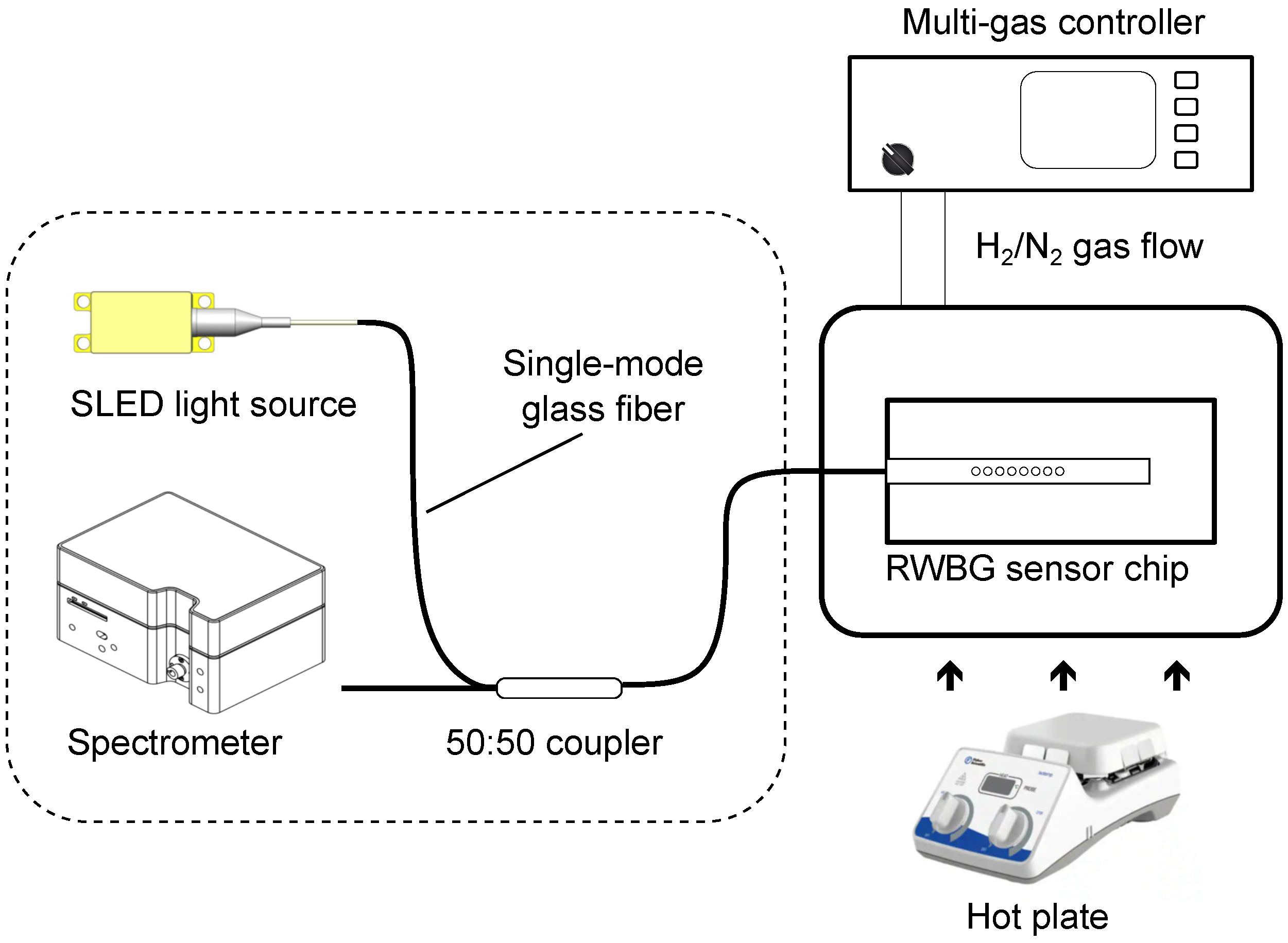
2.5. Optical Measurement Setup
2.6. Sensing Principles
3. Results
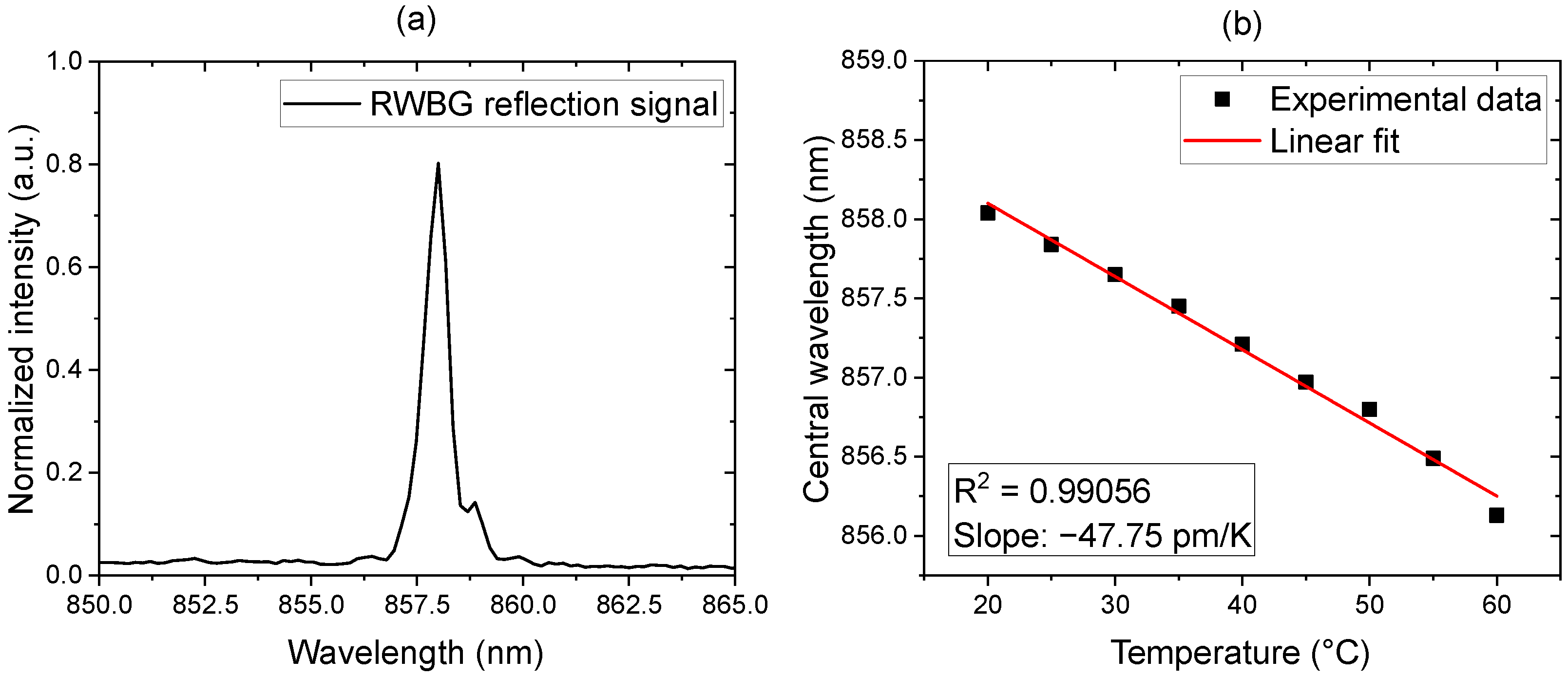
3.1. RWBG Reflection Spectrum and Temperature Dependence
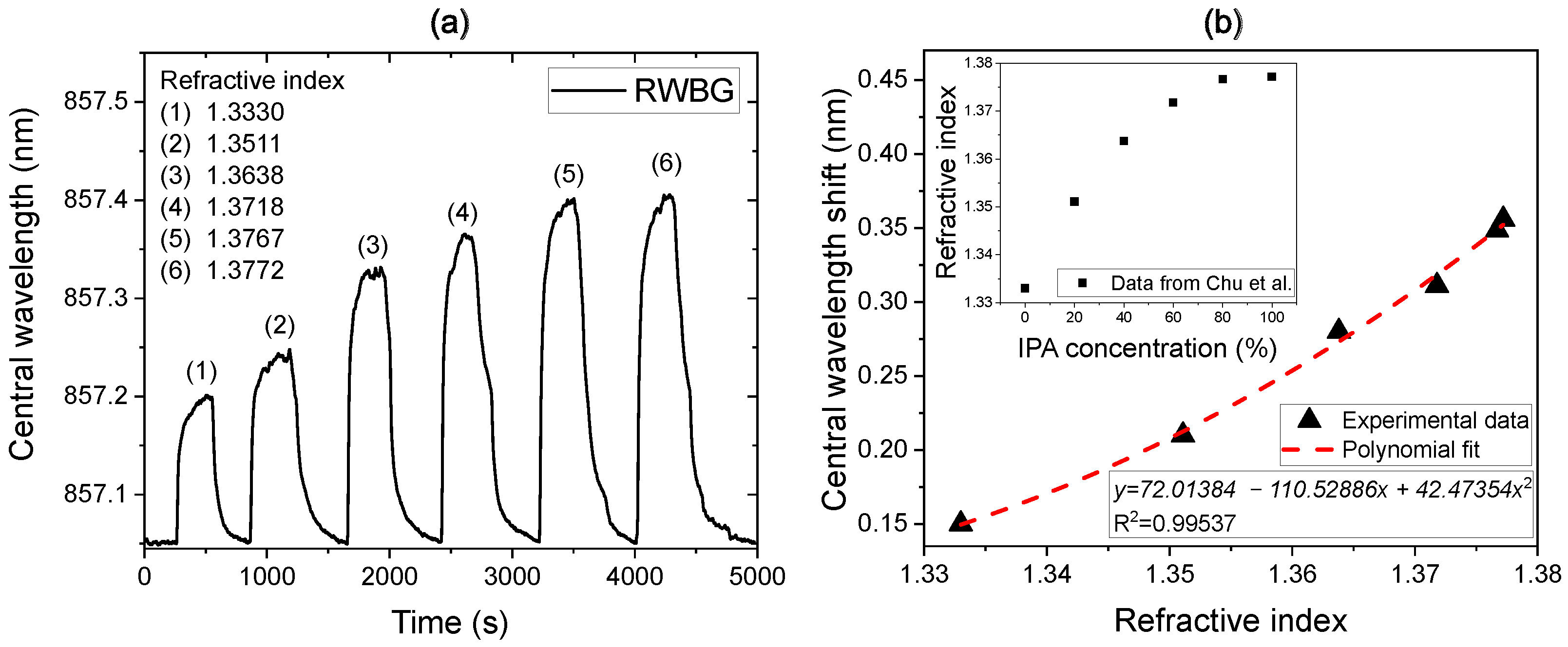
3.2. Liquid-Phase Evanescent Field Measurement: Refractive Index Sensitivity
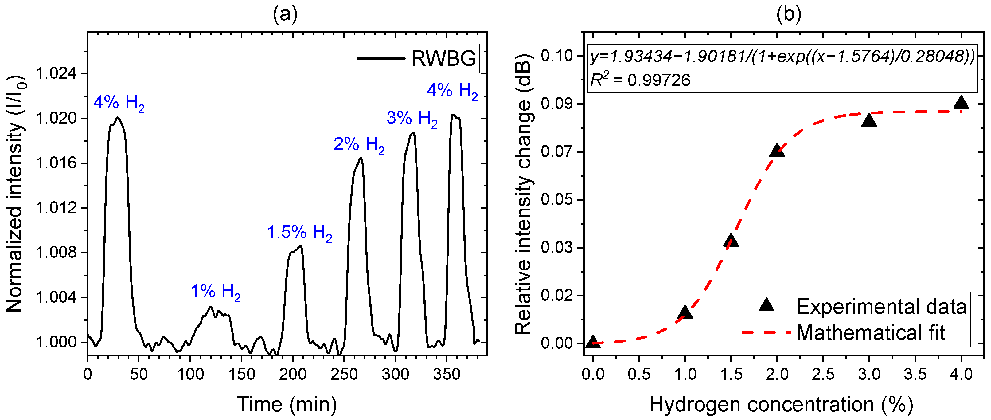
3.3. Gas-Phase Hydrogen Selective Measurement
4. Conclusions and Outlook
Author Contributions
Funding
Institutional Review Board Statement
Informed Consent Statement
Data Availability Statement
Acknowledgments
Conflicts of Interest
References
- Dittrich, P.S.; Manz, A. Lab-on-a-chip: Microfluidics in drug discovery. Nat. Rev. Drug Discov. 2006, 5, 210–218. [Google Scholar] [CrossRef]
- Ríos, Á.; Zougagh, M.; Avila, M. Miniaturization through lab-on-a-chip: Utopia or reality for routine laboratories? A review. Anal. Chim. Acta 2012, 740, 1–11. [Google Scholar] [CrossRef]
- Azizipour, N.; Avazpour, R.; Rosenzweig, D.H.; Sawan, M.; Ajji, A. Evolution of Biochip Technology: A Review from Lab-on-a-Chip to Organ-on-a-Chip. Micromachines 2020, 11, 599. [Google Scholar] [CrossRef]
- Hamid, I.A.; Kamil, Y.M.; Manaf, A.A.; Mahdi, M.A. Fabrication and characterization of micro fluidic based fiber optic refractive index sensor. Sens. Bio-Sens. Res. 2017, 13, 70–74. [Google Scholar] [CrossRef]
- Butt, M.A.; Kazanskiy, N.L.; Khonina, S.N. Advances in Waveguide Bragg Grating Structures, Platforms, and Applications: An Up-to-Date Appraisal. Biosensors 2022, 12, 497. [Google Scholar] [CrossRef]
- Kashyap, R. Fiber Bragg Gratings; Academic Press: Cambridge, MA, USA, 2009. [Google Scholar]
- Kawasaki, B.S.; Hill, K.O.; Johnson, D.C.; Fujii, Y. Narrow-band Bragg reflectors in optical fibers. Opt. Lett. 1978, 3, 66–68. [Google Scholar] [CrossRef] [PubMed]
- Rao, Y. Recent progress in applications of in-fibre Bragg grating sensors. Opt. Lasers Eng. 1999, 31, 297–324. [Google Scholar] [CrossRef]
- Liang, W.; Huang, Y.; Xu, Y.; Lee, R.K.; Yariv, A. Highly sensitive fiber Bragg grating refractive index sensors. Appl. Phys. Lett. 2005, 86, 151122. [Google Scholar] [CrossRef]
- Lee, S.M.; Jeong, M.Y.; Saini, S.S. Etched-Core Fiber Bragg Grating Sensors Integrated with Microfluidic Channels. J. Light. Technol. 2012, 30, 1025–1031. [Google Scholar] [CrossRef]
- Dong, L.; Cruz, J.L.; Reekie, L.; Archambault, L. Tuning and chirping fiber Bragg gratings by deep etching. IEEE Photonics Technol. Lett. 1995, 7, 1433–1435. [Google Scholar] [CrossRef]
- Wochnowski, C.; Kouamo, M.T.; Pieper, W.; Meteva, K.; Metev, S.; Wenke, G.; Vollertsen, F. Fabrication of a planar polymeric deformation Bragg sensor component by excimer laser radiation. IEEE Sens. J. 2006, 6, 331–339. [Google Scholar] [CrossRef]
- Kefer, S.; Dai, J.; Yang, M.; Schmauss, B.; Hellmann, R. Hypersensitive H2 sensor based on polymer planar Bragg gratings coated with Pt-loaded WO3-SiO2. Opt. Lett. 2020, 45, 3601–3604. [Google Scholar] [CrossRef] [PubMed]
- Meyer, J.; Nedjalkov, A.; Kelb, C.; Strobel, G.J.; Ganzer, L.; Schade, W. Manufacturing and Characterization of Femtosecond Laser-Inscribed Bragg Grating in Polymer Waveguide Operation in an IR-A Wavelength Range. Sensors 2020, 20, 249. [Google Scholar] [CrossRef] [PubMed]
- Kumar N, V.; BS, K.; Asokan, S. Selective detection of lead in water using etched fiber Bragg grating sensor. Sens. Actuators B Chem. 2022, 354, 131208. [Google Scholar] [CrossRef]
- S, S.; Vasu, K.S.; Bhat, N.; Asokan, S.; Sood, A.K. Ultra sensitive NO2 gas detection using the reduced graphene oxide coated etched fiber Bragg gratings. Sens. Actuators B Chem. 2016, 223, 481–486. [Google Scholar]
- Strobel, G.J.; Hagemann, B.; Huppertz, T.M.; Ganzer, L. Underground bio-methanation: Concept and potential. Renew. Sustain. Energy Rev. 2020, 123, 109747. [Google Scholar] [CrossRef]
- Farajzadeh, R.; Bartholomeus, P.L.; Hajibeygi, H.; Bruining, J. Exergy Return on Exergy Investment and CO2 Intensity of the Underground Biomethanation Process. ACS Sustain. Chem. Eng. 2022, 10, 10318–10326. [Google Scholar] [CrossRef]
- Abdalwareth, A.; Flachenecker, G.; Angelmahr, M.; Schade, W. Optical fiber evanescent hydrogen sensor based on palladium nanoparticles coated Bragg gratings. Sens. Actuators A Phys. 2023, 361, 114594. [Google Scholar] [CrossRef]
- Micro Resist Technology GmbH. Technical Sheet EpoCore and EpoClad; Micro Resist Technology GmbH: Berlin, Germany, 2023. [Google Scholar]
- Elmogi, A.; Bosman, E.; Missinne, J.; van Steenberge, G. Comparison of epoxy- and siloxane-based single-mode optical waveguides defined by direct-write lithography. Opt. Mater. 2016, 52, 26–31. [Google Scholar] [CrossRef]
- Burgmeier, J.; Waltermann, C.; Flachenecker, G.; Schade, W. Point-by-point inscription of phase-shifted fiber Bragg gratings with electro-optic amplitude modulated femtosecond laser pulses. Opt. Lett. 2014, 39, 540–543. [Google Scholar] [CrossRef]
- Chen, N.; Yun, B.; Wang, Y.; Cui, Y. Theoretical and experimental study on etched fiber Bragg grating cladding mode resonances for ambient refractive index sensing. J. Opt. Soc. Am. B 2007, 24, 439–445. [Google Scholar] [CrossRef]
- Tsigaridas, G.; Polyzos, D.; Ioannou, A.; Fakis, M.; Persephonis, P. Theoretical and experimental study of refractive index sensors based on etched fiber Bragg gratings. Sens. Actuators A Phys. 2014, 209, 9–15. [Google Scholar] [CrossRef]
- Zhang, Y.n.; Peng, H.; Qian, X.; Zhang, Y.; An, G.; Zhao, Y. Recent advancements in optical fiber hydrogen sensors. Sens. Actuators B Chem. 2017, 244, 393–416. [Google Scholar] [CrossRef]
- Pospori, A.; Ioannou, A.; Kalli, K. Temperature and Humidity Sensitivity of Polymer Optical Fibre Sensors Tuned by Pre-Strain. Sensors 2022, 22, 7233. [Google Scholar] [CrossRef] [PubMed]
- Chu, K.Y.; Thompson, A.R. Densities and Refractive Indices of Alcohol-Water Solutions of n-Propyl, Isopropyl, and Methyl Alcohols. J. Chem. Eng. Data 1962, 7, 358–360. [Google Scholar] [CrossRef]
- Eisner, L.; Flachenecker, G.; Schade, W. Doped silica sol layer coatings on evanescent field fiber Bragg gratings for optical detection of nitroaromate based explosives. Sens. Actuators A Phys. 2022, 343, 113687. [Google Scholar] [CrossRef]
- Zhang, W.; Webb, D.; Peng, G. Polymer optical fiber Bragg grating acting as an intrinsic biochemical concentration sensor. Opt. Lett. 2012, 37, 1370–1372. [Google Scholar] [CrossRef] [PubMed]
- Schroeder, K.; Ecke, W.; Willsch, R. Optical fiber Bragg grating hydrogen sensor based on evanescent-field interaction with palladium thin-film transducer. Opt. Lasers Eng. 2009, 47, 1018–1022. [Google Scholar] [CrossRef]
- Yuan, W.; Khan, L.; Webb, D.J.; Kalli, K.; Rasmussen, H.K.; Stefani, A.; Rang, O. Humidity insensitive TOPAS polymer fiber Bragg grating sensor. Opt. Express 2011, 19, 19731–19739. [Google Scholar] [CrossRef]


Disclaimer/Publisher’s Note: The statements, opinions and data contained in all publications are solely those of the individual author(s) and contributor(s) and not of MDPI and/or the editor(s). MDPI and/or the editor(s) disclaim responsibility for any injury to people or property resulting from any ideas, methods, instructions or products referred to in the content. |
© 2024 by the authors. Licensee MDPI, Basel, Switzerland. This article is an open access article distributed under the terms and conditions of the Creative Commons Attribution (CC BY) license (https://creativecommons.org/licenses/by/4.0/).
Share and Cite
Zhang, Z.; Abdalwareth, A.; Flachenecker, G.; Angelmahr, M.; Schade, W. Polymer Waveguide Sensor Based on Evanescent Bragg Grating for Lab-on-a-Chip Applications. Sensors 2024, 24, 1234. https://doi.org/10.3390/s24041234
Zhang Z, Abdalwareth A, Flachenecker G, Angelmahr M, Schade W. Polymer Waveguide Sensor Based on Evanescent Bragg Grating for Lab-on-a-Chip Applications. Sensors. 2024; 24(4):1234. https://doi.org/10.3390/s24041234
Chicago/Turabian StyleZhang, Zhenyu, Ahmad Abdalwareth, Günter Flachenecker, Martin Angelmahr, and Wolfgang Schade. 2024. "Polymer Waveguide Sensor Based on Evanescent Bragg Grating for Lab-on-a-Chip Applications" Sensors 24, no. 4: 1234. https://doi.org/10.3390/s24041234
APA StyleZhang, Z., Abdalwareth, A., Flachenecker, G., Angelmahr, M., & Schade, W. (2024). Polymer Waveguide Sensor Based on Evanescent Bragg Grating for Lab-on-a-Chip Applications. Sensors, 24(4), 1234. https://doi.org/10.3390/s24041234