1. Introduction
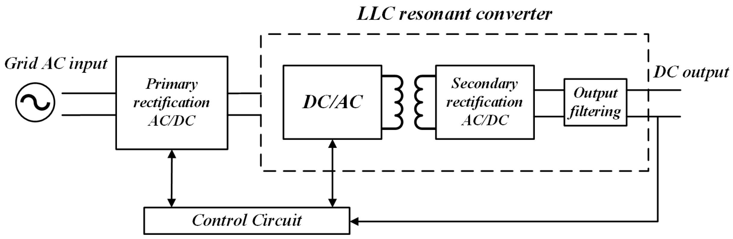
LLC resonant converters have been widely used in auxiliary power systems of urban rail transit systems such as subways, light rails, and maglev trains due to their simple construction, wide input voltage range, high power density, and easy implementation of soft switching characteristics [
1,
2,
3]. However, due to the complex and variable operating environment of LLC resonant converters, their failure rate remains high, which has become a challenge restricting the development of electric vehicles [
4]. When the switching tube fails, it is difficult for the resonant converter to operate near the resonance point while maintaining the output voltage constant using pulse frequency modulation. In addition, CS, as an indispensable feedback component in LLC resonant converter systems, once a fault occurs, it will directly threaten the stability of the entire charging system [
5]. Therefore, in-depth exploration and research on fault diagnosis methods for power switch tubes and CS in LLC resonant converter systems have profound significance for ensuring the safe operation of DC charging piles and promoting the healthy development of the electric vehicle industry.
Power switching transistors frequently experience open and short circuit faults. While serious short-circuit faults can typically be isolated using standard protective devices, open circuit faults usually do not cause immediate severe damage [
6,
7]. However, open-circuit faults can have significant consequences, as prolonged exposure to such conditions may lead to secondary failures in other components, potentially triggering emergency shutdowns in systems like the LLC resonant converter. This critical issue has garnered increasing interest in the research community, particularly regarding the diagnosis of open-circuit faults within these converters. In the realm of fault diagnosis techniques, methods can be broadly classified into two categories [
8,
9,
10,
11]. Data-driven approaches leverage advanced signal processing and artificial intelligence algorithms for fault identification; however, these methods typically require substantial amounts of data and high computational power, making them less suitable for real-time online diagnosis. On the other hand, circuit-driven methods focus on techniques based on voltage, current, or model-based analysis. While there has been research aimed at the rapid detection of voltage characteristics, these methods often necessitate additional sampling and diagnostic circuitry. Together, these insights highlight the importance of developing effective fault diagnosis strategies that can operate reliably under real-time constraints while addressing the unique challenges presented by open-circuit faults [
12,
13,
14,
15,
16]. In contrast, current-based techniques utilize existing signals for diagnosing open circuit faults. Notable methods include the Concordia current mode analysis and average current methods, which have been extensively studied [
17]. However, these approaches generally require longer detection times to ensure accuracy.
In LLC resonant converters, control system faults can arise not only from power switch failures but also from the vulnerability of current sensors (CS) to faults. The closed-loop control inherent in high-performance control systems means that any malfunction in the current sensor can lead to erroneous feedback, which may ultimately trigger system shutdowns. As a result, there is a pressing need for rapid diagnosis of current sensor faults to ensure system reliability. Currently, the diagnostic methods for current sensor faults are mainly categorized into model-driven approaches and data-driven approaches, each offering different advantages and challenges in the fault detection process [
18,
19]. Model-based fault diagnosis methods focus on detecting and analyzing sensor faults by establishing mathematical models and observers of the system. These methods typically have faster diagnostic speeds and lower data requirements. Data-driven fault diagnosis mainly relies on signal processing, artificial intelligence, and other technologies to deeply mine and analyze sensor data, in order to achieve fault diagnosis. As mentioned in reference [
18], an LLC converter open circuit fault diagnosis method based on resonant capacitor voltage observation is proposed. This method provides a foundation for fault tolerance by monitoring the voltage changes of resonant capacitors and quickly locating faulty switches. The algorithm introduced in reference [
19] is a fault diagnosis method based on the short-time Fourier transform (STFT). This algorithm utilizes the main and auxiliary side currents as feature quantities to perform its analysis. By applying the STFT, it analyzes the frequency components of the current to identify faults effectively. For fault localization, the method employs envelope detection to determine the specific arm of the fault. A significant advantage of this approach is that it does not require additional sensors, thereby reducing overall hardware costs.
The literature review in references [
20,
21,
22] discusses various fault diagnosis methods for current sensors (CS) used in converter control systems. These methods share similarities with open-circuit fault diagnosis techniques for power switches, primarily relying on current analysis or model-driven strategies. Among these approaches, model-driven methods are preferred due to their rapid diagnostic capabilities and lower data requirements. Specific techniques include the proportional full-state observer, as mentioned in reference [
23], which is effective for diagnosing current sensor faults and offers quick response times. Additionally, the sliding mode observer, discussed in reference [
24], has also been developed for diagnosing current sensor faults across different types of systems.
The above fault diagnosis methods are all for diagnosing faults in a single power electronic device. Due to the fact that the charging module of the DC charging pile also needs to consider the impact of high-frequency transformers on the inverter circuit and rectifier circuit, which is significantly different from the diagnostic objects of the above diagnostic methods, the above-mentioned methods are difficult to directly apply.
Research has shown that the diagnosis of open circuit faults in power switch tubes and current sensor faults has attracted widespread attention. However, existing research often diagnoses the two types of faults separately, ignoring their mutual influence. Two types of faults, open circuit faults and current sensor faults, can both lead to distortion in phase currents and may exhibit similar characteristics in certain situations. This similarity poses a challenge, as open circuit faults can interfere with the diagnosis of current sensor faults, ultimately affecting the accuracy of diagnosing the open circuit faults themselves. To mitigate the risk of misdiagnosis, it is essential to develop a method capable of simultaneously diagnosing both types of faults effectively. In addition, using a single algorithm to handle two types of faults is simpler than using two algorithms, as analysis, calculations, and code can be partially shared. Meanwhile, this method helps to quickly locate faulty equipment and improve maintenance efficiency. Therefore, it is of great significance to develop a method that can quickly and accurately diagnose both power switch open circuit faults and current sensor faults simultaneously.
Current research on the synchronous diagnosis of open-circuit (OC) faults and current sensor (CS) faults in LLC resonant converters is relatively limited. This paper introduces a diagnosis method that utilizes a reduced-order interval sliding mode observer (SMO) to address both types of faults simultaneously. The article also outlines the primary contributions of this proposed method, emphasizing its potential to enhance fault detection in these systems.
(1) We conducted an innovative study on the faults of power switching tubes, specifically open circuit (OC) and current sensor (CS) faults, in LLC resonant converters using a unified approach. The proposed method simplifies fault detection significantly due to the shared fault phase detection algorithm and common fault identification variables compared to employing two separate methods for each fault type. More importantly, this single-method approach reduces the likelihood of false alarms arising from one fault interfering with the other, thereby facilitating easier subsequent maintenance.
(2) A new reduced-order interval sliding mode observer (SMO) has been developed, incorporating an innovative adaptive sliding mode observer approach and reduced steady-state resonance. This estimation method utilizes a convex weighted sum of upper and lower estimates, effectively accounting for uncertain parameters and unknown disturbances affecting the inverter system, leading to accurate and rapid estimation of phase currents. The advantages of this method include enhanced diagnostic speed and robustness, making it a valuable contribution to fault diagnosis in LLC resonant converters.
(3) The proposed fault detection and identification method relies solely on the direct current (DC) side output current. It features a design for detection variables and their corresponding fault diagnosis thresholds, achieving actual fault detection times of less than 1 ms, which ensures both rapid and robust detection results. The robustness and feasibility of this method have been validated by considering factors such as fluctuations in DC side voltage and imbalances in system parameters.
3. Joint Fault Diagnosis Method
An extended system has been established for System (
7), which decouples the open circuit faults of the power switches through matrix transformations. Additionally, a reduced-order sliding mode observer has been developed to simultaneously estimate the states of the LLC resonant converter system and the current sensor faults. Based on these estimation results, a fault diagnosis method is proposed as shown in
Figure 6.
3.1. Coordinate Transformation
To achieve the evolution detection of LLC resonant converter system faults, the state augmentation method is used to augment the mixed logic dynamic model (
7) of the system containing small faults in current sensors and power switch tube faults, and the augmented system is obtained as follows:
where
,
,
,
,
,
,
,
,
,
.
Remark 1. The invariant zero point of system is located on the left half plane of plane S.
To reduce the number of observation variables in System (
7), a coordinate transformation matrix has been proposed. The purpose of this transformation is to simplify the observation process of the system.
Afterwards, using matrix transformation
, the augmented system (
8) is expressed as
where
,
,
,
.
Remark 2. State component can be directly obtained by the observer in system (10). Therefore, only cannot be directly obtained and needs to be estimated. It is important to highlight that
possesses a non-standard structure. To facilitate further analysis, we introduce the matrix
, which leads to additional modifications of system (
10) as outlined below:
Obviously,
is a full rank matrix. Multiply both sides of System (
10) by
to obtain:
where
,
,
,
,
.
Next, we will apply the following decomposition to System (
12):
Theorem 1. If there exists a positive definite matrix, then the following conditions are satisfied:where , then, expand the fault vector f and decouple it from in system (13). Then, introduce the following matrix M: Now, satisfying condition (14) and multiplying it by M on both sides of System (13) yields: Remark 3. Fault separation has been achieved by effectively enhancing and decoupling the system, completely isolating the switch fault from the state vector . This state vector consists solely of the inverter system state x, current sensor fault , and unknown disturbances d. Notably, open switch faults do not impact the state vector , allowing for accurate estimation of the system state and current sensor faults through the implementation of a system observer, even in the presence of power switch faults.
3.2. Design of Reduced Order Interval Sliding Mode Observer
According to Theorem 1, the following reduced-order interval observer and upper bound observer are constructed for System (
16):
Lower bound observer:
where
is the intermediate variable,
are the upper and lower bounds of the observed values of
, and the expression of the new adaptive approaching law
and
of the upper bound observer is
where
k,
,
, and
are all normal numbers, and the constant
satisfies
. Similarly, the new adaptive approach law of the lower bound observer is similar.
Remark 4. (1) According to Equation (19), when the system state is far from the sliding surface (i.e., when s is large), approaches 0, causing to approach . Due to , is greater than the traditional sliding mode gain k, indicating that the system state converges quickly when it is far from the sliding surface. (2) When the system state approaches the sliding mode surface, i.e., when s is small, approaches 1, causing to approach 1. At this point, is less than k, indicating that chattering can be significantly suppressed as the system state approaches the sliding mode surface. According to Equations (
17) and (
18) of the reduced order interval sliding mode observer, the estimated value
of the state variable
is written as
where the weight factor
satisfies
at any time.
Based on this foundation, we define the constant
as follows:
The linear combination
of
and
is defined as
The expression for
can be obtained as follows:
On this basis, define the error
:
To demonstrate the stability of dynamic error systems, we present the following theorem:
Theorem 2. In the case where sensor failure is not present, there exists a symmetric positive definite matrix P and Q that fulfills the following equation: So, the error dynamic systems (23) and (24) are asymptotically stable. Proof. Choose the following Lyapunov equation:
From Equation (
26), it can be concluded that:
By using the Rayleigh inequality, we can obtain:
The minimum eigenvalue, denoted as
, refers to the smallest eigenvalue of a positive definite matrix
Q. Conversely, the maximum eigenvalue, represented by
, indicates the largest eigenvalue of the same matrix. Additionally, the sign function, denoted as
, is a monotonically increasing function with a value range of
. This property of the sign function ensures that as its argument increases, the output will not decrease, thereby preserving the order of the inputs within the specified range.
Substituting Equations (
28) and (
29) into Equation (
27) yields:
Using the properties of norms, write the above equation in the following form:
To ensure
, there must be:
Under normal conditions, in order for the error between the reduced order interval sliding mode observer and the actual rectifier system to converge to 0 in finite time,
is still required
From Equation (
33), we can obtain
. Substituting it into the above equation, we can obtain:
Building on the preceding analysis, it can be concluded that implies the error between the observed values from the normal state descending order interval sliding mode observer and the actual system will converge to zero within a finite time. This outcome suggests that the system exhibits asymptotic stability. □
Remark 5. The design of the reduced-order sliding mode observer offers significant flexibility, as it imposes no restrictions on the types or occurrence times of current sensor faults. Furthermore, the proposed observer demonstrates the capability to estimate any type of current sensor fault at any given moment, ensuring robust fault detection and diagnosis in varying conditions.
3.3. Fault Detect
The state estimation for the LLC resonant converter system can be derived using the reduced-order interval sliding mode observer. The specific algorithm for this estimation is presented as follows:
Fault detection variables have been created based on the upper and lower limits derived from the reduced-order sliding mode observer. Additionally, adaptive diagnostic thresholds have been established to support the fault detection process.
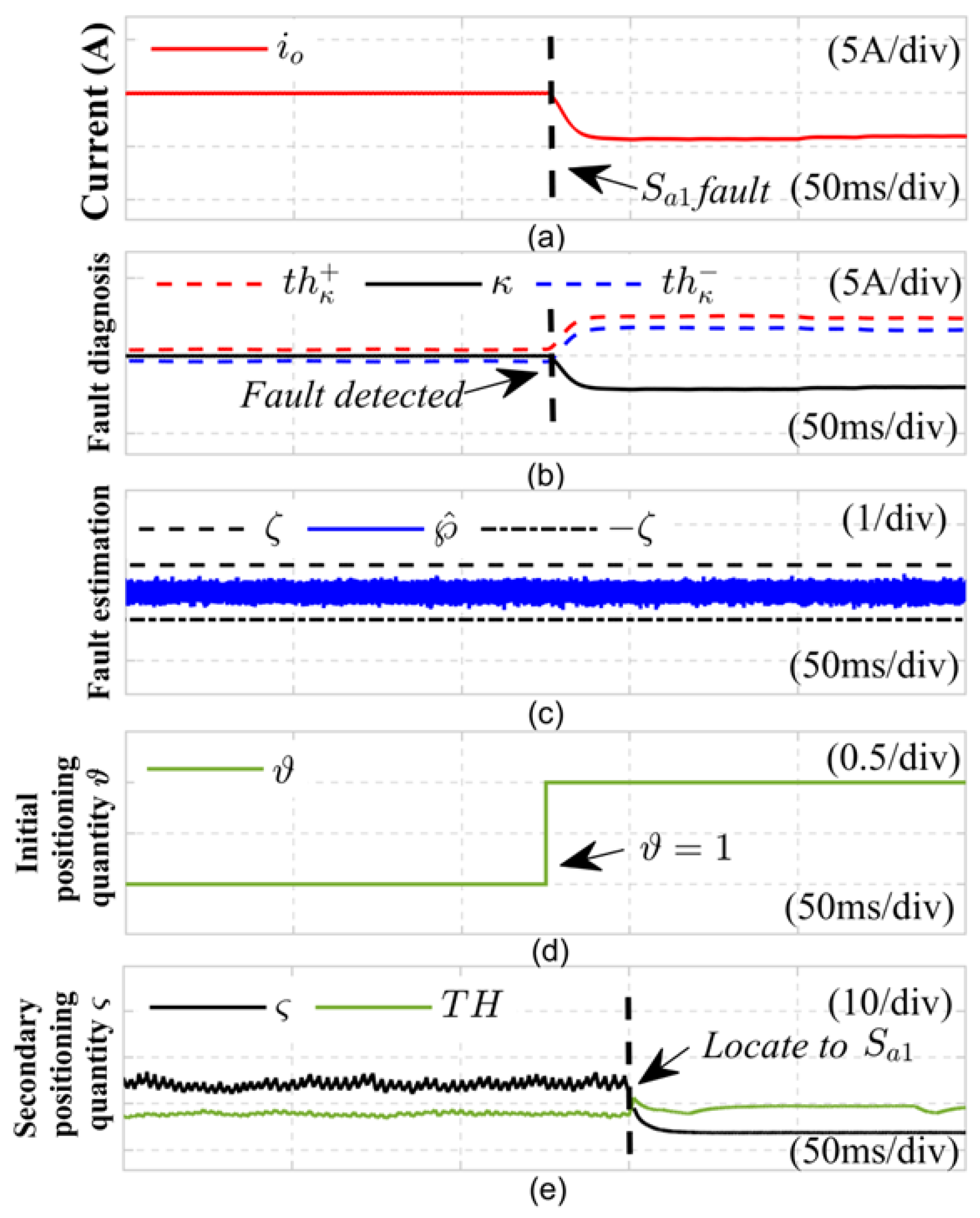
Based on the fault analysis presented above, if a malfunction occurs in either the power switch or the current sensor, the actual output current of the LLC resonant converter will become distorted. This distortion causes the fault detection variable to deviate from zero.
Leveraging the interval characteristics of the reduced-order sliding mode observer, adaptive thresholds for fault detection variables have been developed. Specifically, upper adaptive threshold
and lower adaptive threshold
have been established.
From Equations (
36) and (
37), it can be seen that when the LLC resonant converter system does not experience a fault,
is approximately 0,
,
, that is,
is located between
and
. However, if the LLC resonant converter system encounters an open circuit fault in the rectifier switch or a fault in the current sensor, this may lead to variations in the fault detection variable
as well as the adaptive thresholds
and
. When
is no longer between the adaptive thresholds
and
, a fault in the LLC resonant converter system can be detected. Simultaneously, the fault detection variable
and the adaptive thresholds
and
adjust according to the state of the LLC resonant converter. This adaptive behavior helps prevent false alarms triggered by normal operating conditions, such as fluctuations in load.
3.4. Fault Identification
To effectively identify open circuit faults in inverter switch tubes and faults in current sensors, it is essential to differentiate between two distinct fault types. Consequently, utilizing the estimated upper and lower bounds of the current sensor fault derived from the formula, the estimated value of the current sensor fault can be defined as:
Among them, appropriate constants between
. Sensor fault identification is achieved by analyzing Equation (
38), which indicates that when a current sensor fails, the observed value satisfies
. In contrast, for an open-circuit fault in the inverter switching device, the condition is represented by
. Thus, the estimated value of the sensor fault can serve as a criterion to differentiate between open-circuit faults in the inverter switching device and faults in the current sensor. Additionally, to enhance the accuracy and robustness of the fault identification process, when
is satisfied,
, where
is set as
of the current amplitude before the fault. Based on the above analysis, the identification of open circuit faults in rectifier switch tubes and current sensor faults is as follows:
When indicates an open circuit fault in the rectifier switch tube, indicates a current sensor fault.
3.5. Fault Power Switch Tube Positioning
On the basis of detecting open circuit faults in LLC resonant converters, this section analyzes the distortion characteristics of the output current waveform and designs two fault localization variables based on current residuals by using the residual between the estimated current value of the observer under fault conditions and the normal output current value to achieve open circuit fault localization in LLC resonant converters.
The impact of open-circuit faults in the topology of an LLC resonant converter is significant. When an open-circuit fault occurs in either the bridge arm phase a or the bridge arm phase b, the actual output current waveform will attenuate, resulting in a positive residual between the estimated current and the actual current. Conversely, if an open-circuit fault occurs in the bridge arm phase a or phase b, comparing the actual output current waveform with the estimated current provided by the observer will yield a negative residual.
Building on the previous analysis, this paper employs the distinct current distortion patterns associated with open circuit faults in switching tubes, as well as in the upper and lower bridge arm switching tubes, to establish an initial positioning metric derived from current residuals. The formulation is presented as follows:
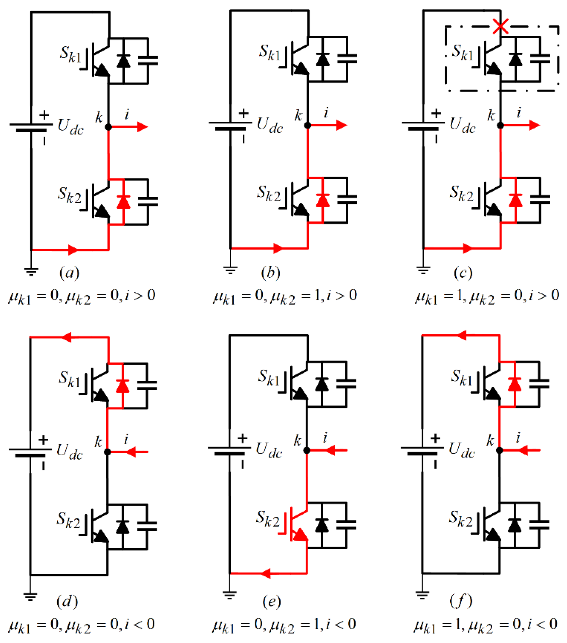
From the examination of faults in power switch tubes, the correlation between the switching function and the switch state during the open circuit fault of phase
a switch tube
is illustrated in
Table 1:
Logical operations can be performed on
Table 1 to obtain the
a phase switching function in the open-circuit fault state of
:
Similarly, the
a phase switching function under the
open-circuit fault state can be derived:
According to the established state space model, the output current depends on the switching signal
. If the a-phase switching function
in the normal state is replaced with the switching function
of the a-phase in the switching fault state, the LLC resonant converter state space model in the fault state can be obtained:
where
,
,
,
,
.
By utilizing the distortion characteristics of the output current of the converter, a fault detection variable
r based on the root mean square of the absolute value of the current is constructed, and its formula is:
Among them, introduces RMS to reduce the impact of peak current and current harmonics.
On this basis, using the estimated current of the observer and the actual output current, the adaptive threshold of the measured variable for open circuit faults is designed as follows:
To further locate the specific faulty switch tube, while ensuring that there are no false alarms in fault detection, within the fundamental wave period after completing the preliminary positioning of the switch tube, the derived switch function
of the a-phase switch tube in the
open circuit fault state is used to replace the switch function in the normal state to design a reduced order interval sliding mode observer in the fault state. The estimated current of the observer in the
fault state is obtained, and then the fault positioning variable and positioning threshold are designed based on the estimated fault current to achieve positioning, that is
By combining Equations (
44)–(
46), the fault power switch of the LLC resonant converter can be located, which can be represented by the following equation:
In the formula, represents the open-circuit fault of the switching tubes in phase a and phase b, respectively.


