Article

Lightweight Two-Layer Control Architecture for Human-Following Robot

by
Gustavo A. Acosta-Amaya
1,
Deimer A. Miranda-Montoya
2 and
Jovani A. Jimenez-Builes
2,*
1
Instrumentation and Control Department, Faculty of Engineering, Politécnico Colombiano Jaime Isaza Cadavid, Medellín 050022, Colombia
2
Department of Computer and Decision Sciences, Faculty of Mines, Universidad Nacional de Colombia, Medellín 050034, Colombia
*
Author to whom correspondence should be addressed.
Sensors 2024, 24(23), 7796; https://doi.org/10.3390/s24237796
Submission received: 4 October 2024 / Revised: 22 November 2024 / Accepted: 4 December 2024 / Published: 5 December 2024
(This article belongs to the Section Sensors and Robotics)

Abstract

:
(1) Background: Human detection and tracking are critical tasks for assistive autonomous robots, particularly in ensuring safe and efficient human–robot interaction in indoor environments. The increasing need for personal assistance among the elderly and people with disabilities has led to the development of innovative robotic systems. (2) Methods: This research presents a lightweight two-layer control architecture for a human-following robot, integrating a fuzzy behavior-based control system with low-level embedded controllers. The system uses an RGB-D sensor to capture distance and angular data, processed by a fuzzy controller to generate speed set-points for the robot’s motors. The low-level control layer was developed using pole placement and internal model control (IMC) methods. (3) Results: Experimental validation demonstrated that the proposed architecture enables the robot to follow a person in real time, maintaining the predefined following distance of 1.3 m in each of the five conducted trials. The IMC-based controller demonstrated superior performance compared to the pole placement controller across all evaluated metrics. (4) Conclusions: The proposed control architecture effectively addresses the challenges of human-following in indoor environments, offering a robust, real-time solution suitable for assistive robotics with limited computational resources. The system’s modularity and scalability make it a promising approach for future developments in personal assistance robotics.

1. Introduction

The aging population has become a matter of high priority for our society. Elderly people require innovative personal assistance solutions to maintain quality of life and the possibility of aging in their communities and homes [1,2]. Mobile robotics and computer vision are two of the most promising technologies for personal assistance in today’s homes [3,4,5]. More and more service robots are being equipped with vision systems that provide richer environmental information than laser scanners and ultrasound ranging systems [6,7].
A broad overview of the potential uses of service robots to assist elderly and disabled individuals is presented in [8]. The scientific literature addressing the application of robotic technologies for monitoring health, safety, mobility, and well-being, as well as assisting elderly individuals with daily living activities, is systematically reviewed, analyzed, and discussed in [9,10].
Innovations such as care robots are proposed in [11,12] to provide support to the daily life activities of elderly people. The robots are equipped with a laser range finder and a floor-sensing system for detecting both moving objects and people. A service trolley and a wheelchair are additionally equipped with inertial sensors to facilitate their localization inside the room. Additionally, a humanoid mobile robot provides services for the recognition and transport of objects [13]. This robot integrates an RGB-D sensor, which is utilized exclusively for object classification and manipulation tasks, rather than for tracking the movement of people. The authors placed this restriction because they considered that the monitoring of people’s activity with visual systems could become invasive to the privacy of individuals [14,15]. The main disadvantage of this facility is its high cost. In our approach, the use of an RGB-D sensor does not compromise the privacy of individuals since the captured frames are only used locally to extract distance and angular displacement information used by the fuzzy controller, and this information is neither stored nor transmitted through communication networks [16,17,18].
A relevant issue has to do with the acceptance or not by the users of the new technologies of assistance and care. In that sense, a study related to the answer to the question of how both older people and caregivers perceive the possibility of using an assistive robot for nutritional support was conducted in [19]. According to the authors, most participants considered the possibility of using a robot to improve the diet of the elderly by giving advice on healthy eating or controlling the amount of food consumed [20]. Another study conducted in [21] was focused on identifying the requirements and needs of people with Alzheimer’s and early dementia concerning robotic assistants.
One of the most required tasks in assistive robotics is the safe tracking of people. A human-following mobile robot system equipped with a laser range scanner was developed in [22]. The data provided for the laser were used to detect the position of the target based on the estimation of both shin positions of the person.
The authors consider the most significant contributions of this paper to be (1) providing evidence that a lightweight behavior-based control architecture enables a robotic system with limited computational resources to perform complex tasks, such as tracking people indoors; (2) offering a detailed explanation of the processes involved in modeling, design, testing, and adjusting each layer of the proposed architecture, and its integration into a final solution; and (3) presenting extensive validation experiments that demonstrate the feasibility of the proposed solution to address complex problems, such as the autonomous tracking of people by a robot.
This paper presents the design and implementation results of the human-following mobile robot platform Carlitos-Care. The article is structured as follows: Section 2 details the development of the mobile robot platform, including the effector modeling and the design and implementation of the embedded controllers. Section 3 presents the results and discusses the validation experiments, focusing on the behavior-based control architecture and the design and characterization of fundamental fuzzy behaviors. Finally, Section 4 summarizes the conclusions.

2. Materials and Methods

The development of the human-following mobile robot platform Carlitos-Care was guided by principles of modularity, scalability, simplicity, and cost-effectiveness. This section outlines the technical components and methodologies employed in constructing the robotic platform, including the modeling of effectors, the design and implementation of embedded controllers, and the integration of control systems. Each step in the design process was meticulously planned and executed to ensure the platform’s capability to perform complex tasks within limited computational constraints.

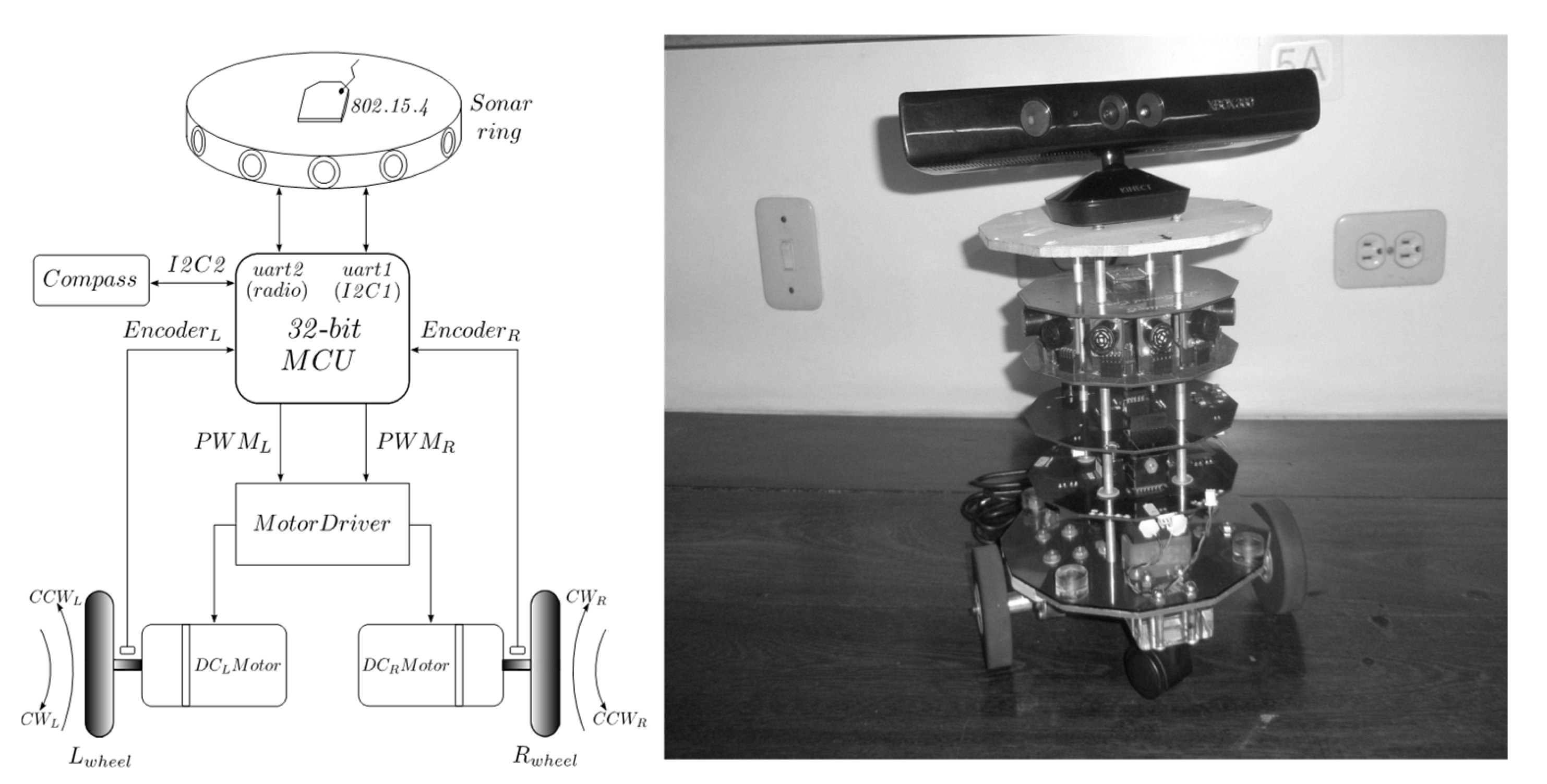
2.1. Mobile Robotic Platform

The mobile robot platform was developed having in mind modularity, scalability, simplicity, and low-cost criteria. It was named “Carlitos” for Car-Like Autonomous Robot System and has been used by the authors to research and teach engineering. The robotic platform is organized into layers: effectors, control, sensing, and communications. From a hardware perspective, each level corresponds to a printed circuit board (PCB) with a dodecahedron pattern. Each PCB not only contains the electronic components and connectors but also constitutes an integral part of the structure of the robot.
Figure 1 shows the block diagram and physical appearance of the follower robot. The layer of effectors is composed of two DC motors with gearboxes and quadrature encoders coupled to the axes of the motors. A dual H-bridge driver amplifies the PWM signals generated by the control layer. The main component of the control layer is a 32-bit NXP microcontroller, specifically MCF51QE128 (Freescale Semiconductor, Austin, EE. UU).
Other than odometry, the sensing layer has a CMPS03 digital compass for the estimation of the robot’s orientation and a sonar ring with twelve ultrasonic modules SRF02 for distance measurements of surrounding obstacles. Wireless data transfer between the robotic platform and a host PC is provided by an IEEE 802.5.4 IMS module. The system is powered by a couple of 7.4 V, 2200 mA-h, lithium-ion batteries (Li-ion).

2.2. Effector Modeling and Control

Algorithm 1 was implemented to facilitate the mathematical modeling of the robot’s effectors. It allows researchers to apply a time-variant PWM (Pulse-Width Modulation) signal to both DC motors, acquire data from rotary encoders, and transmit this information to a computer through an 802.15.4 wireless interface. A frequency of fs = 1/T = 10 Hz was established for data sampling.
The robot was placed in an obstacle-free indoor environment for the data acquisition experiments of the encoders coupled to DC motors, waiting for a start command from the host PC. Upon receipt of the order, a PWM signal with an initial DC (Duty Cycle) value of 20% was applied to each motor. Every 1.5 s, the DC value was increased by 20% until the maximum value of 80%. After reaching this value, the algorithm began to decrease this value in steps of 20% every 1.5 s until it reached again the minimum value of 20%; at that point, the experiment concluded, and the robot stopped. During robot displacement, the count of pulses from the encoders was sent to the host PC at the sampling rate previously mentioned.
Figure 2 shows the responses of both the left and right motor to the time-variant PWM signal. We use a First-Order Plus Dead-Time (FOPDT) model to describe the dynamics of the motors. With a proper choice of system delay θ, time-constant τ, and system gain K parameters in Equation (1), a useful model for the low-level controller’s design purposes was obtained.
G s = K e θ s τ s + 1 = 2.636 e 0.1159 s 0.2222 s + 1
Specifically, step response data corresponding to a 40% to 50% applied PWM signal were used to develop the effector models. The System Identification Toolbox™ in Matlab® (version R2021a, MathWorks, Portola Valley, CA, USA) facilitated this process, yielding a correlation factor of 94.02%. With this model in hand, the design of the control layer for the effectors was undertaken using both pole placement and internal model methods, which are described below.
Algorithm 1: Application of time-variant PWM signal to robot’s effectors. Source: Authors.
Input: Start command from host PC through an 802.15.4 link
Output: Pulse counts from encoders in host PC through ab 802.15.4 link
Initialize internal hardware of microcontroller:
 UART at 9600,8,N,1 for 802.15.4 communications; timer TPM3 for 1 KHz PWM signals generations;
 TPM1, TPM2 for count pulses of encoders;
 interruptions of internal RTC for 0.1 s sampling interval
FlagUpDown = 0; DCLeftmotor = 0; DCRightmotor = 0;
CountPulsesrightmotor = 0; CountPulsesleftmotor = 0;
 repeat
  while uart reception register empty do
   wait;
  end
  RcvCommand = uart reception register;
 until RcvCommand ≠s”;
 repeat
  if FlagUpDown = 0 then
   DCLeftmotor += PWMUpDown;
   DCRightmotor += PWMUpDown;
  end
  else
   DCLeftmotor −= PWMUpDown;
   DCRightmotor −= PWMUpDown;
  end
  PWMtimeinterval = 15;
  repeat
   while no RTC interruption do
    wait;
   end
   CountPulsesLeftmotor = internal count register TPM1;
   CountPulsesLeftmotor = internal count register TPM1;
   while uart busy do
    wait;
   end;
   uart transmition register = CountPulsesLeftmotor;
   while uart busy do
    wait;
   end
   uart transmition register = CountPulsesRightmotor;
   CountPulsesLeftmotor = 0; CountPulsesRightmotor = 0;
   PWMtimeinterval ——;
  until PWMtimeinterval = 0;
  if DCLeftmotor = 80 and DCRightmotor = 80 then
   FlagUpdown = 1;
  end
until DCLeftmotor < 20 and DCRightmotor < 20;

2.2.1. Pole Placement Method

In this method, requirements on the closed-loop response are obtained by placing a pair of complex conjugate poles in the s-plane [23]. The next equation corresponds to the transfer function regardless of the delay.
G s = 11.8632 s + 16.3636 = 0.725 0.06111 s + 1
where τeq = 0.0611 is used to calculate the sampling period as follows:
0.2 τ e q + θ T 0.6 τ e q + θ
0.0354 T 0.1062
A sampling period T = 0.1 s close to θ = 0.1159 was selected and implemented through periodic interrupts of the internal RTC (Real-Time Counter) module of the MCF51QE128 microcontroller. In the z-domain, the pulse transfer function of the system in an open loop is given by Equation (5).
H G z = 0.8306 z + 0.1501 z 2 z 0.6376
Considering a D(z) PI controller, the characteristic equations will be
1 + D z H G z = 0
1 + q 0 z + q 1 z 1 0.8306 z + 0.1501 z 2 z 0.6376 = 0
Thereby, we obtain
z 4 1.637 z 3 + 0.8306 q 0 + 0.6376 z 2 + 0.124673 q 0 + 6.66223 q 1 z + 0.124673 q 1 = 0
To meet the requirements of a bounded response in the 2% band, a settling time ts = 0.711 s, and a damping coefficient ζ = 0.8, we have
ω n = 4 ζ t s = 7.032 r a d s
where ωn is the natural frequency. The dominant poles must be placed in
z 1,2 = z e ± θ i
z = e ζ ω n T = 0.5697
θ = 180 π ω n T 1 ζ 2 = 24.176
z 1,2 = 0.5697 e ± 24.176 i = 0.5197 ± 0.2333 i
The fourth-order characteristic polynomial that meets the specifications of the dynamic behavior of the system will then be
z 0.5197 + 0.2333 i z 0.5197 0.2333 i z + a z + b = 0
z 4 + a + b 1.0394 z 3 + a b 1.0394 a 1.0394 b + 0.324517 z 2 + 0.324517 a 1.0394 a b + 0.324517 b z + 0.324517 a b = 0
Equating similar terms from Equations (1) and (8), we have
1.6376 = a + b 1.0394
0.8306 q 0 + 0.6376 = a b 1.0394 a 1.0394 b + 0.324517
0.124673 q 0 + 0.8306 q 1 = 0.324517 a 1.0394 a b + 0.324517 b
0.124673 q 1 = 0.324517 a b
By solving the system of Equations (16)–(19), we can determine the values of q0 and q1
q 0 = 0.2853 , q 1 = 0.1867
Finally, from these values we obtain the pole placement controller (PPC)
D z = M z C z = q 0 z + q 1 z 1 = 0.2853 z 0.65439 z 1

2.2.2. Internal Model

This model-based design method states that control can be achieved when the control system incorporates, implicitly or explicitly, some representation of the process to be controlled [24,25,26]. The design of an internal model controller (IMC) begins with determining the parameter λ, an adjustable parameter that defines the response speed of the system, the controller gain Kc, and the integral time τi using
λ 1.7 θ , λ 1.7 0.1159 , λ 0.197
λ 0.2 τ , λ 0.2 0.2222 , λ 0.0444
For a low gain in the controller and a slow response of the feedback system, we choose λ = 0.197. The other two parameters can be calculated as follows
K c = τ K λ = 0.2222 2.636 0.197 = 0.4278
τ i = τ = 0.2222
Equations (26) and (27) are used to calculate the q0 and q1 parameters.
q 0 = K c 1 + T 2 τ i = 0.4278 1 + 0.1 2 × 0.2222 = 0.5162
q 1 = K c 1 T 2 τ i = 0.4278 1 0.1 2 × 0.2222 = 0.3265
From these values we obtain IMC given by Equation (28).
D z = M z C z = q 0 z + q 1 z 1 = 0.5162 z 0.6325 z 1
The difference equation that implements the control law by the internal model method is Equation (29), where m(k) is the actual output, m(k − 1) the previous control output, and e(k) and e(k − 1) the actual and previous error signals.
m k = q 0 e k + q 1 e k 1 + m k 1 = 0.5162 e k + 0.3265 e k 1 + m k 1

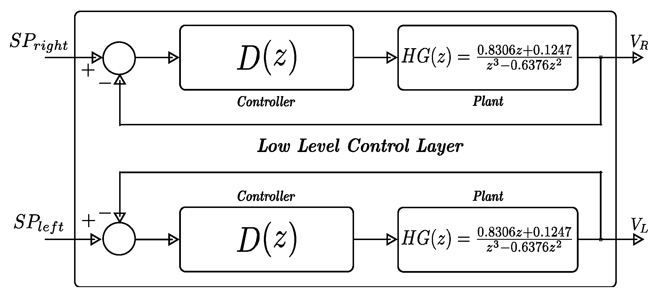
2.2.3. Low-Level Control Architecture

Figure 3 shows the proposed low-level architecture, where the controller (z) is selected based on the performance in the experimental tests (see Section 3.1).

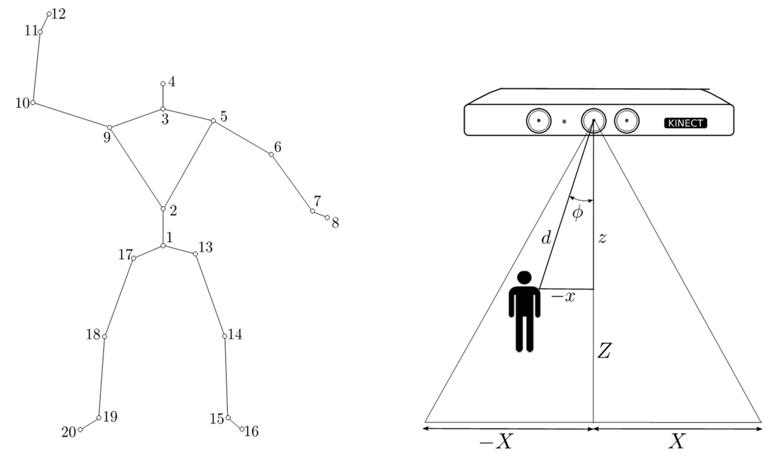
2.3. Linear and Angular Displacements

Currently, the control paradigms that dominate the robotics scene are deliberative, reactive, and hybrid [27], each with distinct characteristics and computational requirements. Deliberative architectures excel in route planning and environment modeling through techniques such as SLAM and search algorithms like A* or D*. However, these approaches are computationally expensive due to the intensive processing needed to build and maintain maps and to manage uncertainties using probabilistic methods. Consequently, they often require advanced hardware, limiting their applicability in low-cost systems [28].
Hybrid architectures, on the other hand, combine deliberative planning with reactive layers that execute immediate actions in response to stimuli. While they offer a balance between long-term planning and real-time responsiveness, they inherit the high computational cost of environment modeling and global planning from deliberative systems. Additionally, the complexity of coordinating these layers increases their resource demands, making them more suitable for systems with intermediate computational capabilities but less ideal for resource-constrained hardware [29].
In contrast, reactive architectures based on fuzzy behaviors, such as the one proposed in this study, eliminate the need for environment modeling and global planning. By directly processing sensor data and employing fuzzy rules to manage uncertainty, these architectures achieve efficient control with simple mathematical operations and real-time responsiveness. This significantly reduces computational load, making them well suited for implementation on low-cost microcontrollers without compromising performance in specific applications, such as human-following tasks [30].
We chose a reactive behavior-based scheme for our high-level control layer because of the following advantages: (a) low computational cost, (b) easy implementation through soft computing methods, (c) high-speed response to changes in the environment thanks to the direct mapping between sensing and actuating, and (d) a high degree of modularity [31]. It is noteworthy that some of its disadvantages are the difficulties in establishing a set of adequate basic behaviors to support a given task of navigation, the emergence of unpredictable behaviors that occur from the process of switching behaviors according to the environment state, and no execution of planning tasks because it does not have a model of the environment [32]. Now, when we consider the problem of an autonomous robot that follows a person, a heuristic approach suggests that if the person is just right in front of the robot and walks away without altering their orientation angle to the robot, a linear displacement allows the robot to follow the person without losing them [33]. However, when the person makes sudden changes in orientation, the robot must quickly correct its orientation, so that the person will not disappear from the field of view (FOV) of the robot’s sensor [34]. Based on this reasoning, we identified two basic behaviors:
Linear Displacement. The objective of this behavior is to maintain an approximate distance of 1.5 m between the robot and the person whom it follows. This behavior generates a velocity output that is sent as references (SPright and SPleft) to the left and right embedded controllers (see Figure 4). With the same speed reference for both motors, approximately one linear displacement of the differential robot is achieved. To a greater distance, a greater reference speed is generated, and the laser distance has a lower reference value. This behavior takes control of the robot’s effectors when the person walks away, in the perpendicular direction to the sensor surface and a FOV delimited by ϕminϕϕmax, where ϕ is the angular position of the person with respect to the RGB-D sensor and ϕmin and ϕmax are the angular values that determine the threshold for the activation/deactivation of this behavior.
Angular Displacement. This behavior takes control of robot’s effectors when the angular position of the person is out of the range ϕminϕϕmax to the normal sensor surface (see Figure 4). The objective of this behavior is to keep the person within the field of view (FOV) of the sensor and avoid losing track of them. This behavior operates at a higher hierarchical level and overrides the linear displacement behavior when the angular measurement falls outside the specified range. We use the Kinect Software Development Kit SDK v. 10 and its skeletal tracking functionality to obtain and track the coordinates of skeleton joints. This functionality provides 3D coordinates of twenty skeletal joints; using Matlab, we isolated the coordinates of the skeletal joint named spine 1 and took it to be the person’s position. As shown in Figure 4, the lateral displacement x and depth z were used to calculate the distance d and orientation ϕ of the person by means of Equations (30) and (31).
d = x 2 + z 2
ϕ = t a n 1 x z
Both behaviors were synthesized employing Mamdani-type Fuzzy Inference Systems (FISs) [35]. Table 1 specifies the input and output variables associated with the fuzzy behavior-based control.
Each linguistic variable was characterized as a tuple of the form:
{ X , T x , U , G , M }
where X is the name of the linguistic variable, T(x) the set of terms associated with the fuzzy sets to be defined in the universe of discourse U, G are the syntactic rules for establishing the terms T(x), and M is a semantic rule that associates to each term in T(x) a fuzzy set. Below, a detailed discussion of the design process of the behavior-based fuzzy controllers is presented.

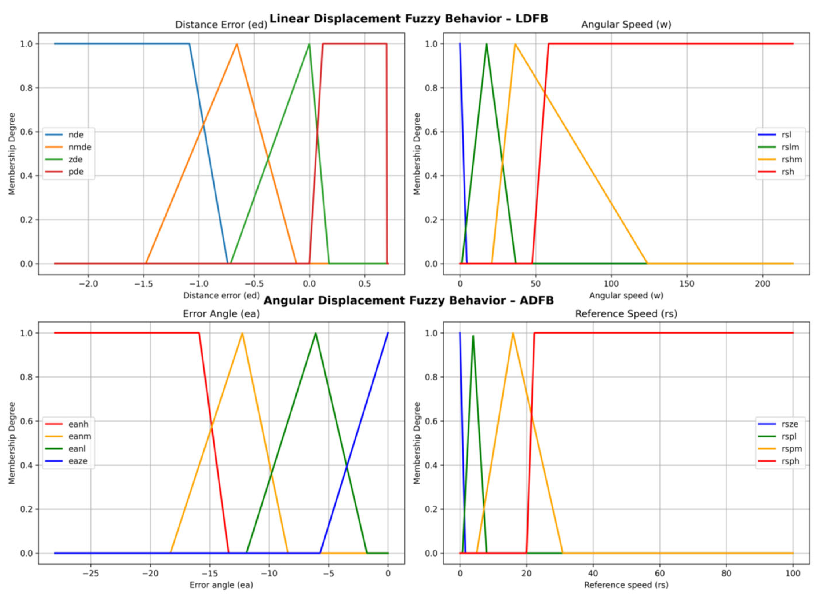
2.3.1. Linear Displacement Fuzzy Behavior (LDFB)

The universe of discourse U for the input variable ed was established using Equation (33), where spd is the distance set-point and d is the distance to the person.
e d = s p d d
Assuming that a comfortable distance of the robot to a person is approximately spd = 1.5 m, since the experimental operating range of our Kinect sensor goes from 0.8 m to 3.8 m, the universe of discourse U can be established. For the output variable Vr, minimum and maximum values of velocity Vrmin = 0 and Vrmax = 220 pp/T were established. The complete characterization of both input variables, according to Equation (17), can be seen in Table 2. The fuzzy sets with which the universe of discourse U was partitioned allow us to establish how far from the Comfort Distance (ComDi) the person being followed is. Set nde, for example, makes it possible to determine that the person is at a much greater distance than the ComDi, while nmde indicates that they are somewhat further away from this value. On the other hand, zde is used to establish that the distance between the robot and the person is very close to ComDi and pde that the distance is less than this value; in this case, the robot is very close, and this could make the person uncomfortable.
As for the output variable ω, its universe V was partitioned into four sets, where rls places reference values very close to zero to IMCs, in such a way that the robot moves very slowly or stops completely. Similarly, sets rslm, rshm, and rsh set, respectively, low, medium, and high reference speeds to the controllers. Figure 5 graphically presents the input and output fuzzy sets for LDFB.
Because one of our design assumptions was to develop a lightweight control architecture, we chose the simplest membership functions like trapezoidal (trapmf) and triangular (trimf). The set of inference rules for the LDFB is as follows:
R1: if ed is nde, then ω is rsh.
R2: if ed is nmde, then ω is rshm.
R3: if ed is zde, then ω is rslm.
R4: if ed is pde, then ω is rsl.

2.3.2. Angular Displacement Fuzzy Behavior (ADFB)

Regarding this behavior, it is desirable for the robot to keep the person it follows directly in front. For a differential robot like the one in Figure 6, this means executing a pure angular displacement around its central point, Cp, aiming to quickly respond to changes in the orientation of the person being followed so that they remain within the sensor’s field of view. In such a case, the motor speeds should be equal in both magnitude and direction of rotation.
Indeed, a counterclockwise rotation of the robot (CCWrobot) is achieved when the speeds of both motors are equal and both rotate in a clockwise direction (CW), as indicated in Table 3. This should be the robot’s movement when the person being followed moves to their left. On the other hand, when the person moves to the right, both motors should rotate counterclockwise (CCW) to produce a clockwise movement of the robot (CWrobot), as shown in Figure 6 and Table 3.
Based on the previous discussion, the sensor’s field of view, defined by −28° ≤ ϕ ≤ 28°, can be restricted to 0° ≤ ϕ ≤ 28°, using the sign of the original range to ensure that the embedded system generates the appropriate motor rotation directions. Since the goal is for the robot to maintain an orientation close to zero degrees relative to the person it is following, the universe of discourse for the variable of interest can be calculated as:
e a = s p a ϕ e a m i n = 0 28 = 28 , e a m a x = 0 0 = 0 ,
The universe of discourse of this variable is then:
W = e a R 28 e a 0
For the linguistic variable ea, we considered the next set of terms:
T x = { e a n h , e a n m , e a n l , e a z e }
where:
eanh: Error angle negative-high. This indicates that the person that the robot is following is far away from the angular position set-point (spa = 0°).
eanm: Error angle negative-medium. The angular distance between the robot and the person is moderate.
eanl: Error angle negative-low. This indicates that the angular distance between the robot and the person is low.
eaze: Error angle zero. This means that the angular distance between the robot and the person is near zero, which is the desired angular distance.
We considered the following partition of the universe of discourse in fuzzy sets:
error angle negative-high eanh → trapmf [−28, −28, −15.88, −13.4].
error angle negative-medium eanmtrimf [−18.3, −12.24, −8.41].
error angle negative-low eanltrimf [−11.9, −6.073, −1.77].
error angle zero eazetrimf [−5.71, 0, 0].
We consider the reference velocity for angular displacement, Vra, like the output linguistic variable. The reference velocities of both the right and left motor controllers are equal in magnitude and have the same rotation direction such that the robot rotates on its middle point. Referring to Figure 6, if both motors rotate counterclockwise (CCW), the robot moves counterclockwise (CWrobot). But, if the two motors rotate in the CW direction, then the robot moves clockwise around Cp. For this variable, we define the universe of discourse as (see Equation (37)):
Y = V r a R 0 V r a 100
where Vra is given in pp/T. The expression reference speed and linguistic modifiers like zero, positive low, positive medium, and positive high are considered as syntactic rules. So, the set of linguistic terms for this variable are as follows (see Equation (38)):
T x = { r s z e , r s p l , r s p m , r s p h }
where:
rsze: Reference speed zero. This indicates that the reference velocity for both motors is too close to zero and the robot is stopped.
rspl: Reference speed positive low. Reference velocity is low. The robot makes angular displacements at low velocity.
rspm: Reference speed positive medium. The angular displacements of the robot are made at a moderate velocity.
rsph: Reference positive speed high. The robot makes fast angular displacements, avoiding that the person that it follows escapes from its visual field. The following fuzzy sets were considered in the implementation of this fuzzy controller:
reference speed zero rszetrimf [0, 0, 1.603].
reference speed positive-low rspltrimf [0.748, 3.95, 8.013].
reference speed positive-medium rspmtrimf [5.02, 15.92, 30.9].
reference speed positive-high rsphtrapmf [20, 22.33, 100, 100].
To implement the angular displacement behavior, the following rule base was established:
R1 if ea is eanh, then Vra is rsph.
R2 if ea is eanm, then Vra is rspm.
R3 if ea is eanl, then Vra is rspl.
R4 if ea is eaze, then Vra is rsze.
Table 4 summarizes and organizes this information for better identification, and Figure 5 graphically presents the input and output fuzzy sets for ADFB.

2.3.3. Control Architecture

Figure 7 illustrates the two-layer control architecture proposed in this work, which integrates fuzzy behavior-based control (left) and low-level motor control (right). For our fuzzy behavior-based control architecture, the simplest coordination scheme was considered, named Arbitration or Action Selection. In this method, typically found in subsumption-type architectures, only one behavior can be active at one time [36]. In our case, the highest priority level was assigned to the angular displacement behavior, which ensures that the person followed by the robot does not disappear from the visual field of the Kinect sensor. Angular displacement behavior subsumes or cancels the linear displacement when the angular position of the person is in the range |ϕ| > 8°. The overall block diagram of our architecture is shown in Figure 7. The behavior selection module (BSM) implements the hierarchical coordination scheme based on the environment state captured with the Kinect sensor.
The outputs of the fuzzy behavior-based subsystem are the speed set-points Vr, which are sent to the robot via radio link 802.15.4 and are used as reference inputs for the PI-embedded controllers in the robot. Algorithms 2 and 3 implement the control architecture proposed. The first was coded in MatLab version R2021a and the second in C++ language version 20.
Algorithm 2: Behavior-based Control Layer. Source: Authors.
Input: Time t f during which the person is followed by the robot
Output: Velocity set-point Vr for PI embedded controllers, distance d between the person and the robot, angular position ϕ of the person respect to the robot, flag of active behavior behave_flag, and text file for data logging data.txt
// behave_flag = 1: robot angular displacement in CW //
// behave_flag = 2: robot angular displacement in CCW //
// behave_flag = 3: linear forward displacement in CCW //
Vr = 0; t = 0; d = 0; ϕ = 0;
behave_flag = 0; x = 0; z = 0;
Initialize the PC UART at 9600,8,N,1 for 802.15.4 communications;
Open(“data.txt”, Write); /* create and open a data logging text file for write */
Run the Kinect skeletal tracking functionality;
repeat
z ← the z coordinate of the joint spin 1; x ← the x coordinate of the joint spin 1;
d = sqrt(x2 + y2); ϕ = tan−1(x/z);
 if −25 ≤ ϕ ≤ −8 or 8 ≤ ϕ ≤ 25 then
  Deactivate linear displacement behavior;
  Vr = fuzzy_angular_behavior(ϕ);
  if −25 ≤ ϕ ≤ −8 then
   behave_flag = 2;
  else
   behave_flag = 1;
  end
 else
  Desactivate fuzzy angular displacement behavior;
  Vr = fuzzy_linear_behavior(d);
  behave_flag = 3;
 end
UART_transmission(behave_flag,Vr);
 Write(“data.txt”, Vr, d, ϕ, behave_flag);
until t > t f;
behave_flag = 0;
UART_transmission(behave_flag);
UART_close();
Close(“data.txt”);
Algorithm 3: Embedded Control Layer. Source: Authors.
Input: Active behavior flag behave_flag, Velocity set-point Vr, and stop_character for stop the robot
Output: DC_Left and, DC_Right for setting the Duty Cycle of the PWM control signals for left and right motors
Initialize internal UART of microcontroller at 9600,8,N,1 for 802.15.4 communications;
Enable interrupts for data reception in the UART;
Configure the internal timer module TPM1 to counting pulses of the left motor encoder;
Configure the internal timer module TPM2 to counting pulses of the right motor encoder;
Configure the internal timer module TPM3 to generate 1 KHz PWM control signals;
Configure the internal RTC module to generate periodic interrupts each T = 0.1 s;
Vr = 0; DC_left = 0; DC_right = 0;
stop_character = 0; behave_flag = 0;
LW_pulses = 0; RW_pulses = 0;
repeat
 wait;
until t > t f;
// Interrupt Service Routine for internal RTC time out ISR RTC_time_out{
LW_pulses ← (TPM1 counting register) // pulse counting left motor
RW_pulses ← (TPM2 counting register) // pulse counting right motor
switch behave_flag do
 case 1 do
  left motor rotationCCW;
  right motor rotationCCW; // robot rotates in CW
 case 2 do
  left motor rotationCW;
  right motor rotationCW; // robot rotates in CCW
 case 3 do
  left motor rotationCCW;
  right motor rotationCW; // robot moves forward
 otherwise do Vr = 0;
end
DC_left = left_motor_PI_controller(LW_pulses, Vr);
DC_right = right_motor_PI_controller(RW_pulses, Vr);
TPM1 duty cycle register = DC_left;
TPM2 duty cycle register = DC_right;
}
// Interrupt Service Routune for UART reception
ISR UART_reception{
behave_flag ← (UART_reception_register);
Vr ← (UART_reception_register);
}

2.4. Experimental Designs

Experiments were designed to validate each layer of the control architecture, both at low and high levels. For the low-level control, performance metrics commonly used in classical control systems were considered. For the high-level control, the focus was on tracking the linear and angular displacements of a person relative to the robot. To evaluate behavior switching, test paths were designed that combined both linear and angular displacements. All experiments were conducted in controlled indoor environments, with no obstacles present, ensuring that the results were obtained under ideal conditions.

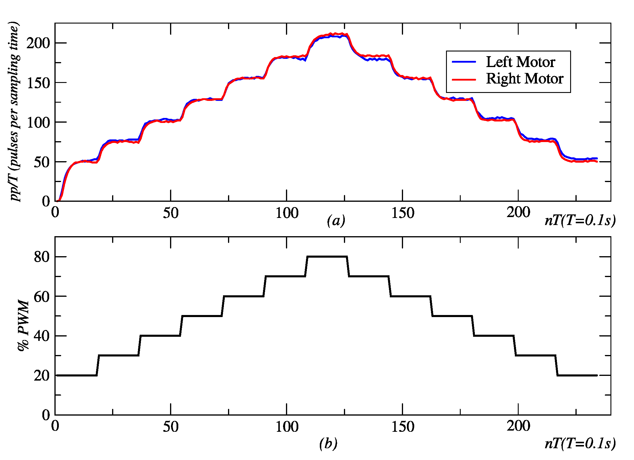
2.4.1. Experimental Design for Embedded Controllers

Both control strategies, pole placement and IMC, were encoded and flashed in the internal memory of the microcontroller. Two simple paths of robot displacement were considered: linear and circular trajectories.
Approximate linear displacements were achieved when the speed set-points for both the left and right motor controllers had the same value. Time-based displacements of 15 and 20 s were regarded with velocity set-points of 100 and 150 pp/T (pulses per sampled period). A board marker was used to mark the path of the robot on the floor. For the performance evaluation of the controllers, the Integral of Absolute Error (IAE) and the Integral of Squared Error (ISE) were used. Equations (39) and (40) define these metrics.
I A E = t 0 t f e t d t k = k 0 k f e k T
I S E = t 0 t f e t 2 d t k = k 0 k f e k T 2
where t0 and k0 represent the initial time values, while tf and kf correspond to the final time values for the evaluation of these error-based metrics. Additionally, kT denotes the sampling rate.

2.4.2. Experimental Design for Fuzzy Behaviors

Our fuzzy behavior-based control architecture was validated through three different kinds of experiments: (a) linear approximation and tracking of a person, (b) angular approximation and tracking of a person, and (c) a combination of angular and linear displacements to test the behavior coordination mechanism proposed. These experiments were conducted in controlled indoor environments with no obstacles between the depth camera and the person being followed. As a limitation, the system’s performance has not yet been evaluated in dynamic or cluttered environments, where obstacles or occlusions could impact the accuracy of the depth sensing and the behavior coordination. This highlights the need for future studies to assess its robustness in more complex scenarios.

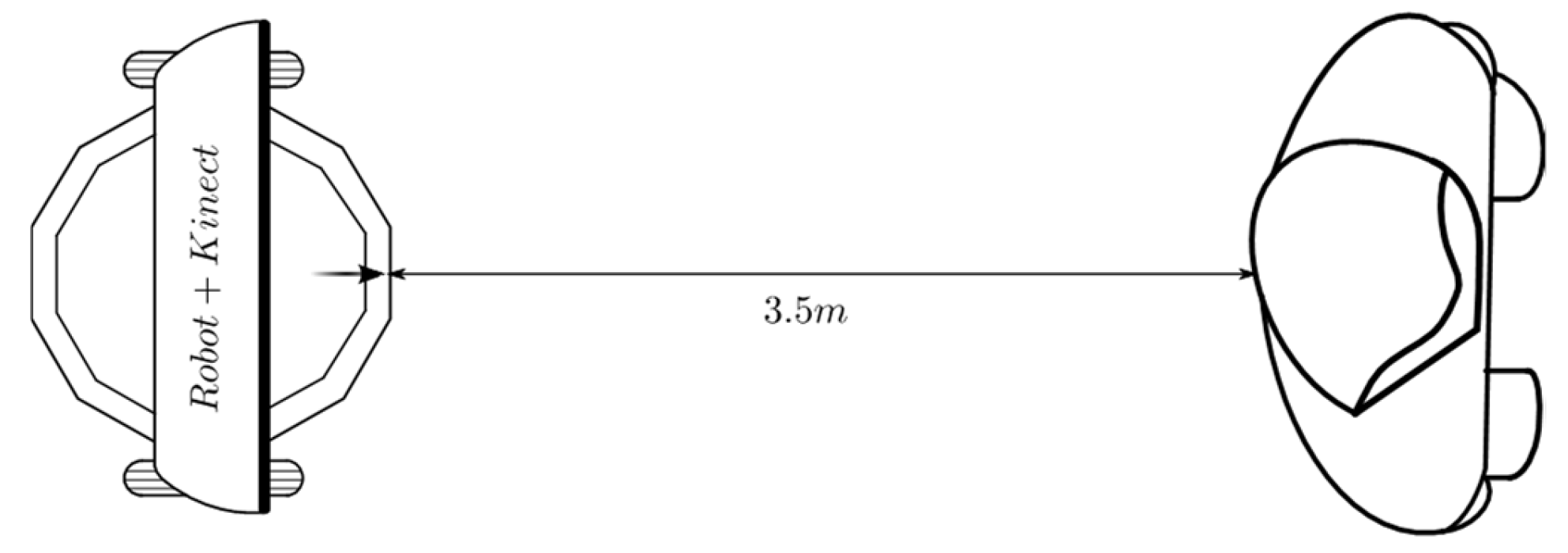
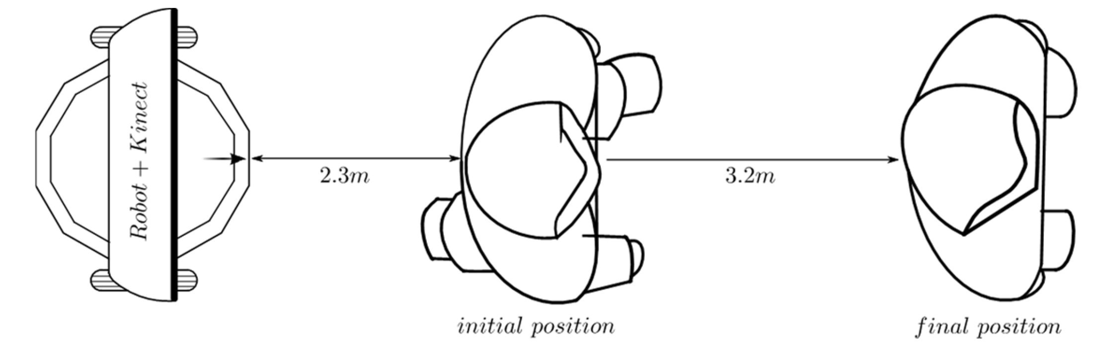
2.4.3. Experimental Design for Linear Tracking

Figure 8 shows the first experimental set-up for linear displacement. A person who is just in front of the robot, at 3.5 m, remains standing. Once the robot is ordered to start moving, and after the Kinect recognizes and starts monitoring the skeletal joints, the linear displacement behavior begins to generate references of velocity that are sent to the embedded controllers to allow the robot to follow the person.
A variation in this experiment is shown in Figure 9. The person is initially located at 2.3 m from the robot P1. In this position, the person waits until the robot is close to 1.3 m in P0 and stops its movement. Then, the person begins to move away from the robot until they reach the final position P2 located at 3.2 m.

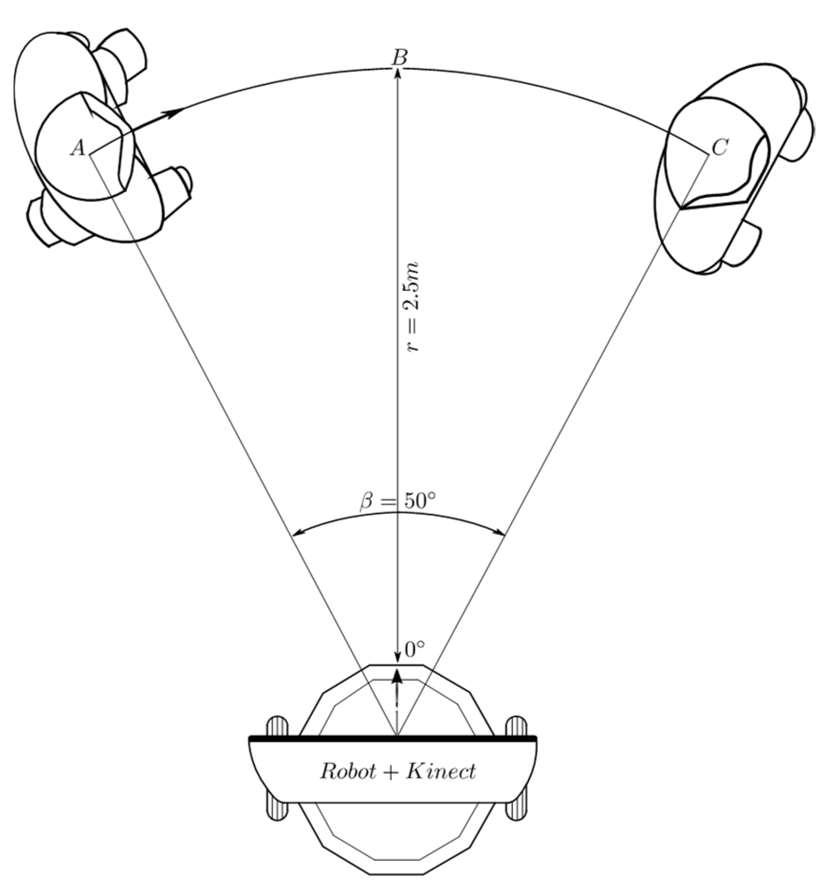
2.4.4. Experimental Design for Angular Tracking

Figure 10 shows the first experimental set-up for the validation of angular displacement behavior. Initially, the person is located at point A, at an angular position of 25° with respect to the coordinate system of the Kinect® sensor, at 2.5 m. The initial orientation of the robot coincides with the bisector OB, which corresponds to 0° in the Kinect® coordinate system. When the test begins, the robot detects that the person is located on its left side, so it makes a counterclockwise angular displacement until the angle of orientation of the person, relative to the sensor, is about 0°.
Once the person observes that the robot is in front of them, they begin a displacement over the path described by the arc AC and stop in C, waiting for the robot to finish its rotation.

2.4.5. Experimental Design for Behavior Coordination

The experimental set-up shown in Figure 11 corresponds to the first test of the coordination mechanism. Initially, the person is located at 2.5 m away, with an orientation angle of 25 relative to the robot. The robot is oriented in the direction of the bisector OB. When the test starts, the person waits until the robot corrects its orientation and stops. From that moment, the person moves in the path comprising the arc AC and, at point C, the person stops and waits a little while until the robot changes its orientation towards them. Then, the person starts moving on a straight line between points C and D and stops when they reach this latter point. The robot keeps moving until it finally corrects its distance and angular position with respect to the person who is waiting at point D.
Figure 12 describes the second conducted test for the validation of the coordination scheme of behaviors. Initially, the person is located 2 m away, with an orientation of −15° degrees relative to the robot, which is oriented in the direction of the line segment OB. Once the test begins, the person waits until the robot is oriented toward them, and then the person starts moving over the circumference of radius r = 2.0 m in the CW direction. When the person reaches point B, they start moving in the direction of the straight line BC and finally stop at point C. The test ends when the robot stops at about 1.3 m and inside of the range −8° ≤ ϕ ≤ 8°. Figure 13 shows the obtained results.

3. Results and Discussion

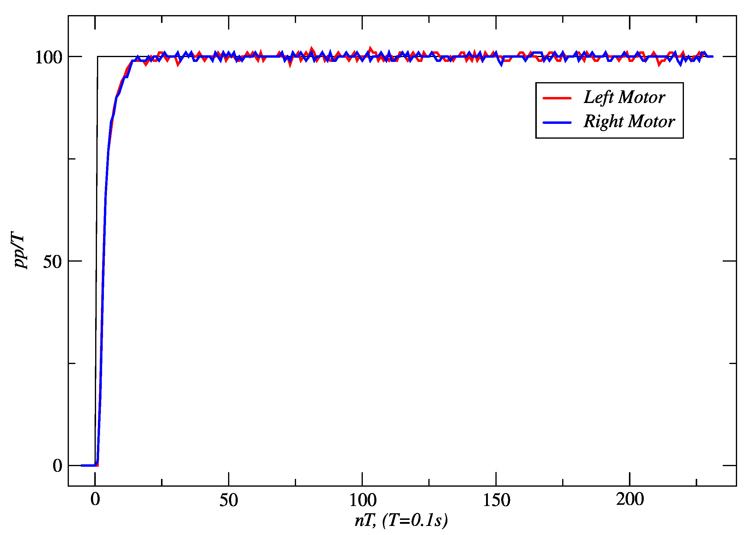
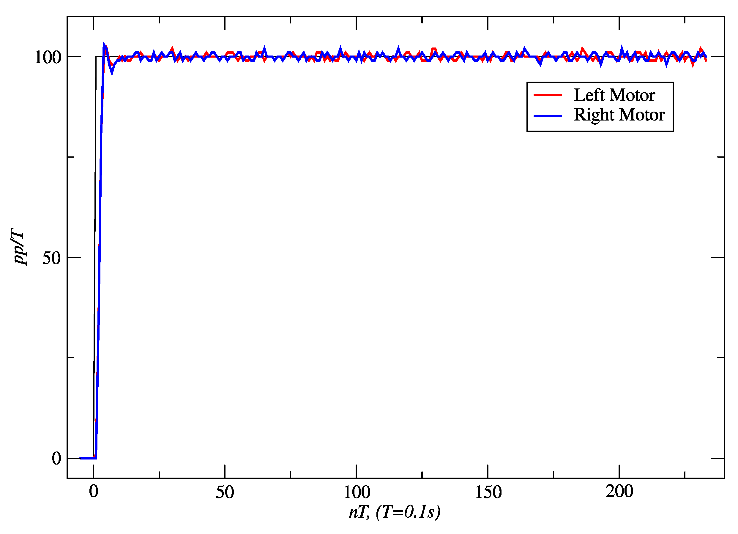
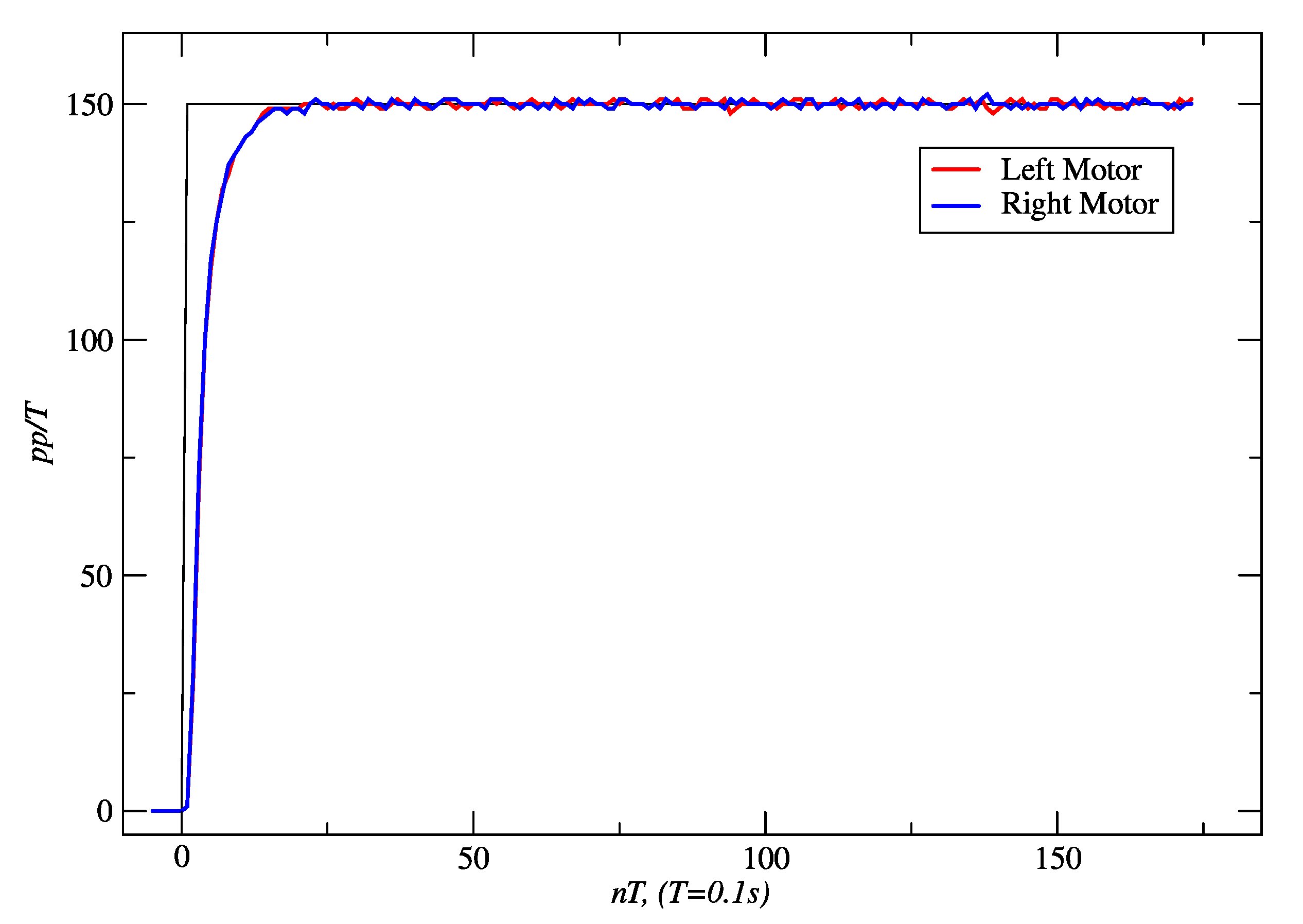
3.1. Results for Embedded Controllers

Figure 14 shows the response obtained for a linear distance of 458 cm and a time slot of 20.49 s with PPC, and Figure 15 shows the response of IMC. With the latter controller, 466 cm was reached in 20.63 s. In both cases, the velocity set-point was 100 pp/T. In both cases, it is seen in the figures that the steady-state error converges to zero. In addition, it was determined from the true trajectory of the robot on the floor that the maximum deviations to the reference straight line were 9 mm for PPC and 5 mm for IMC.
Figure 16 and Figure 17 show the results obtained for PPC and IMC for a set-point of 150 pp/T. With PPC, 514 cm was traveled in 15.43 s. In the case of IMC, the distance reached was 531 cm in 15.76 s. In the first case, the settling time (ts) was 1.5 s, and the steady-state error was zero. The maximum linear deviation from the straight line was 6 mm. In the latter, ts was 1.2 s, the steady-state error was zero, no overshoot occurred, and the maximum linear deviation obtained was 12 mm.
Table 5 shows the values of IAE and ISE performance indexes obtained from linear displacement experiments with a set-point of 150 pp/T, for both the right and left motors of the controllers. The better controller is the one with the minimum IAE and ISE values. So, IMC was selected for the final implementation on the robot.

3.2. Results for Fuzzy Behaviors

The following are the results obtained for the validation of the fuzzy behaviors described in Section 2.3.1 and Section 2.3.2, corresponding to Figure 8, Figure 9 and Figure 10.

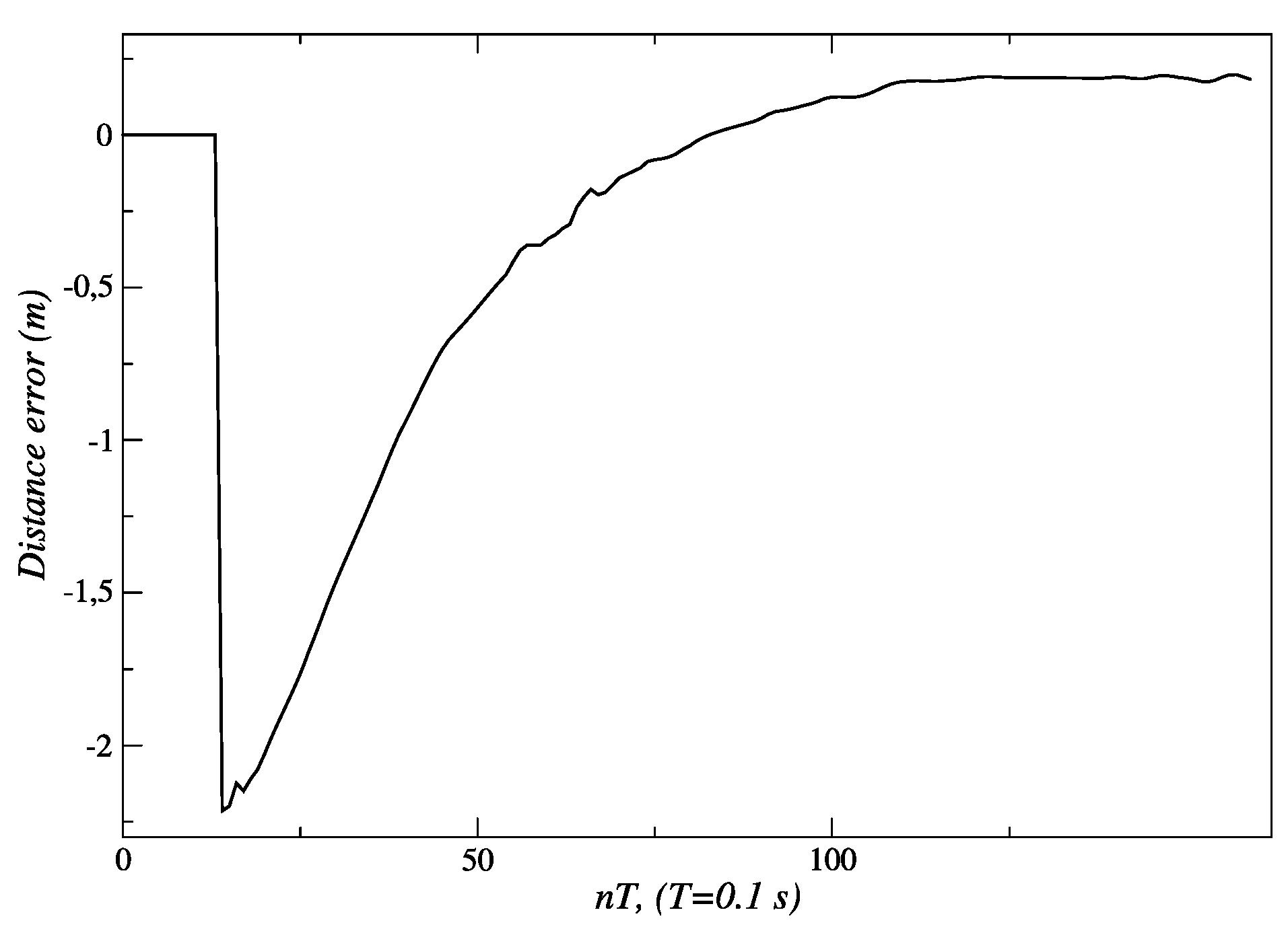
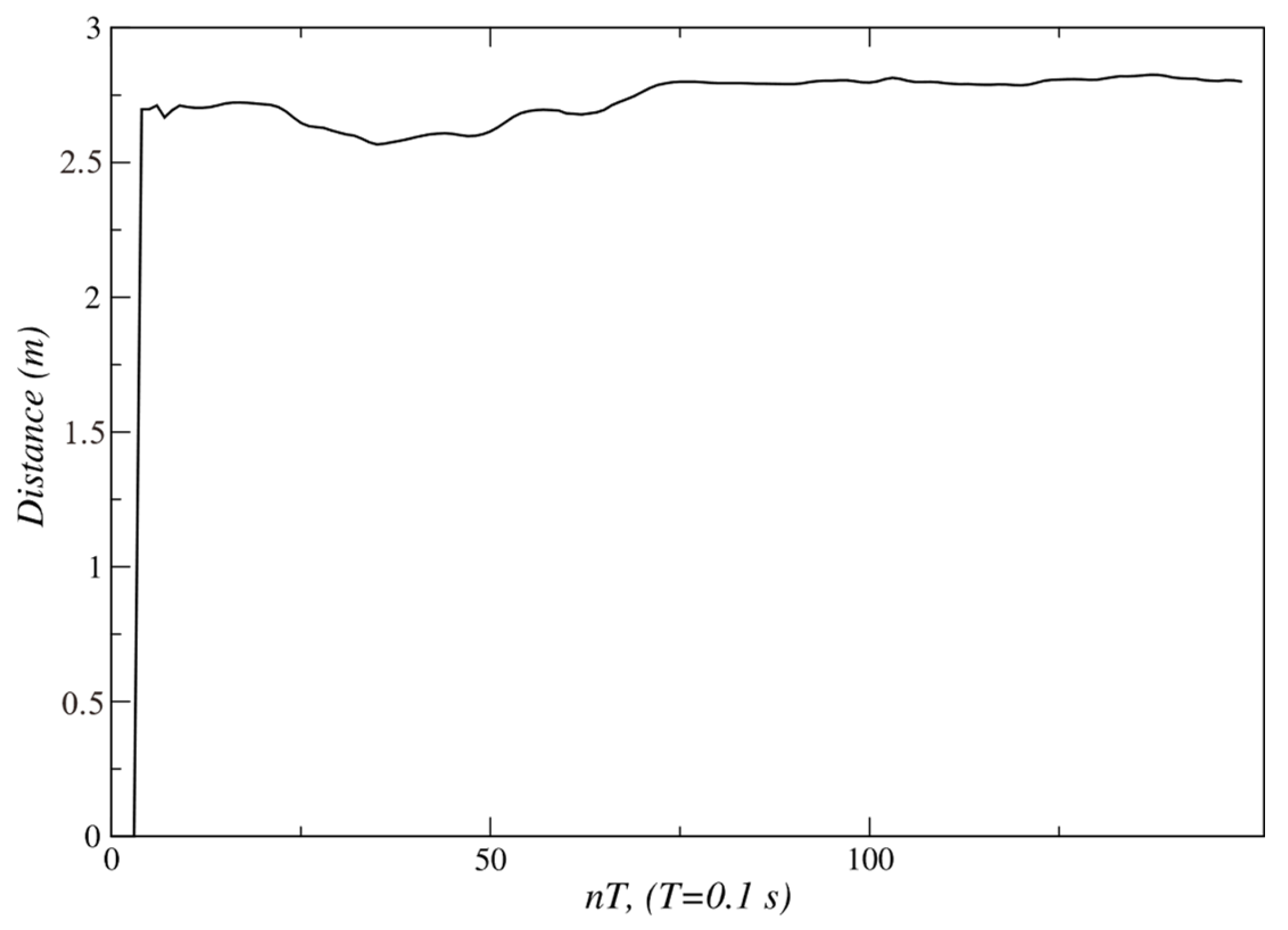
3.2.1. Results for Linear Tracking

For the linear displacement shown in Figure 8, the robot reduces the distance to the person, and its linear velocity decreases until it eventually stops. Figure 18 shows how the initial distance of 3.5 m is reduced until it reaches the final value of 1.3 m. In this figure, and all the following ones, the first sampling periods (fifteen in this case) are used by the Kinect sensor to start the execution of the skeleton tracking algorithm. Figure 19 shows an initial value of the distance error of −2.3 m, and a final value of 0.2 m at the end of the path; this is the steady-state error of this fuzzy controller.
In Figure 20, the changes in set-points of velocity that are sent to the embedded controller can be seen. An initial set-point of 140 pp/T is generated for a quick approach to the person. Subsequently, velocity set-points are reduced to 60 pp/T s near t = 45 T s, and then to 20 pp/T s around t = 75 T s. Finally, when the robot reaches 1.3 m, this behavior sends a velocity set-point of 0 pp/T to the embedded controllers, and the robot stops.
As mentioned earlier, a variation in the experiment described in Figure 8 is shown in Figure 9. It can be seen how the robot approaches the person and stops at approximately 1.3 m. Soon after, the person begins to move away from the robot, and the fuzzy behavior responds by generating velocity references that allow the robot to follow the person to try to keep 1.3 m between them. This can be seen in Figure 21 around t = 100 T s. Once the person begins to move away from the robot, it is seen how the distance error increases its value up to −1.8 m (see Figure 22), just when the person reaches the final position P2 around t = 125 T s.
Figure 23 shows how the behavior responds in this experiment. When it is detected that the person begins to move away, new velocity set-points are sent to the controllers, until they reach a value of 140 pp/T near t = 110 T s. This way the robot remains near the person, reacting to their displacement changes. As the robot approaches, the fuzzy behavior decreases the values of velocity set-points until the distance to the person, at the end of the path, is about 1.3 m (see Figure 21 and Figure 22). From that moment, the speed set-points take a value of 0.0 pp/T.

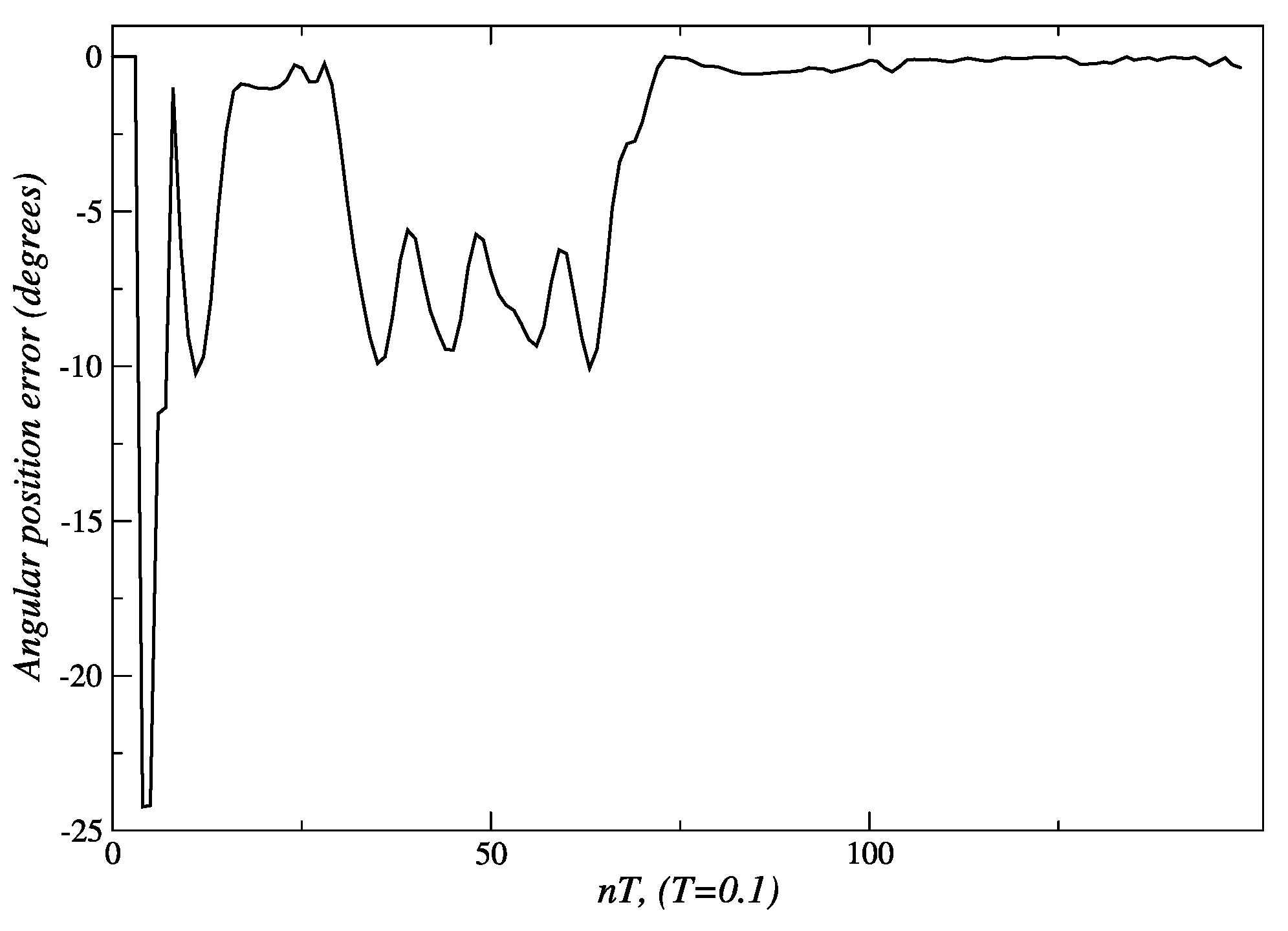
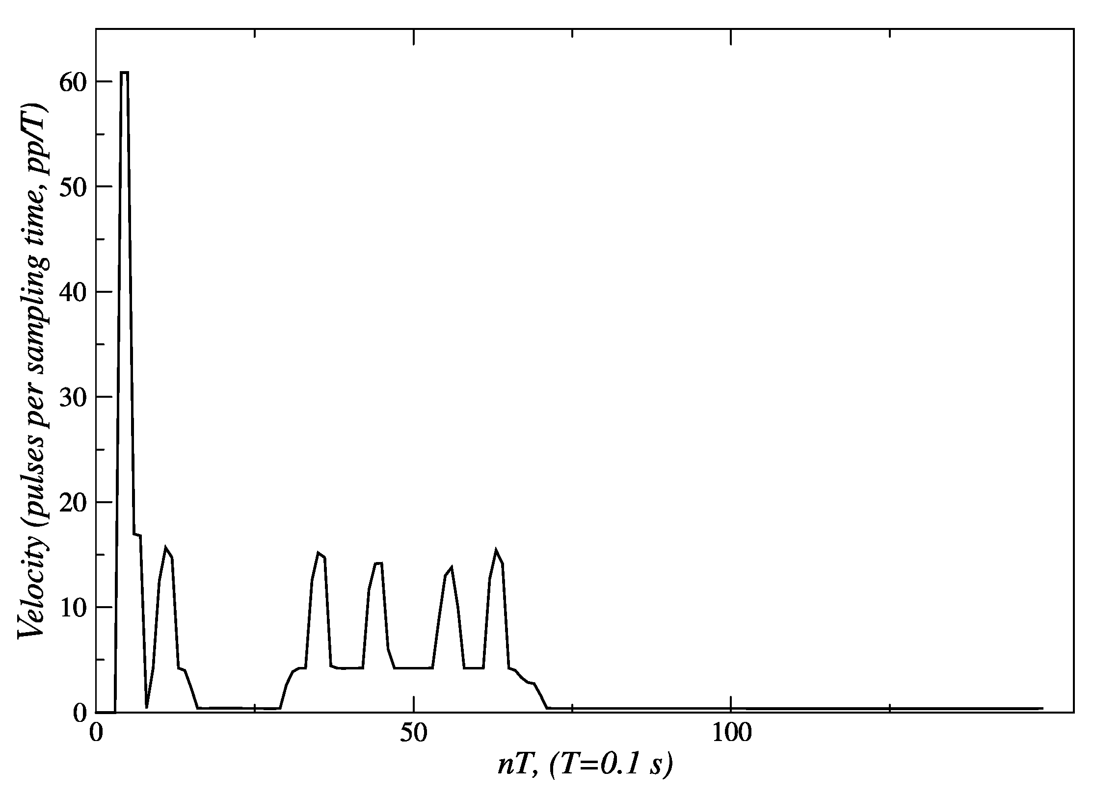
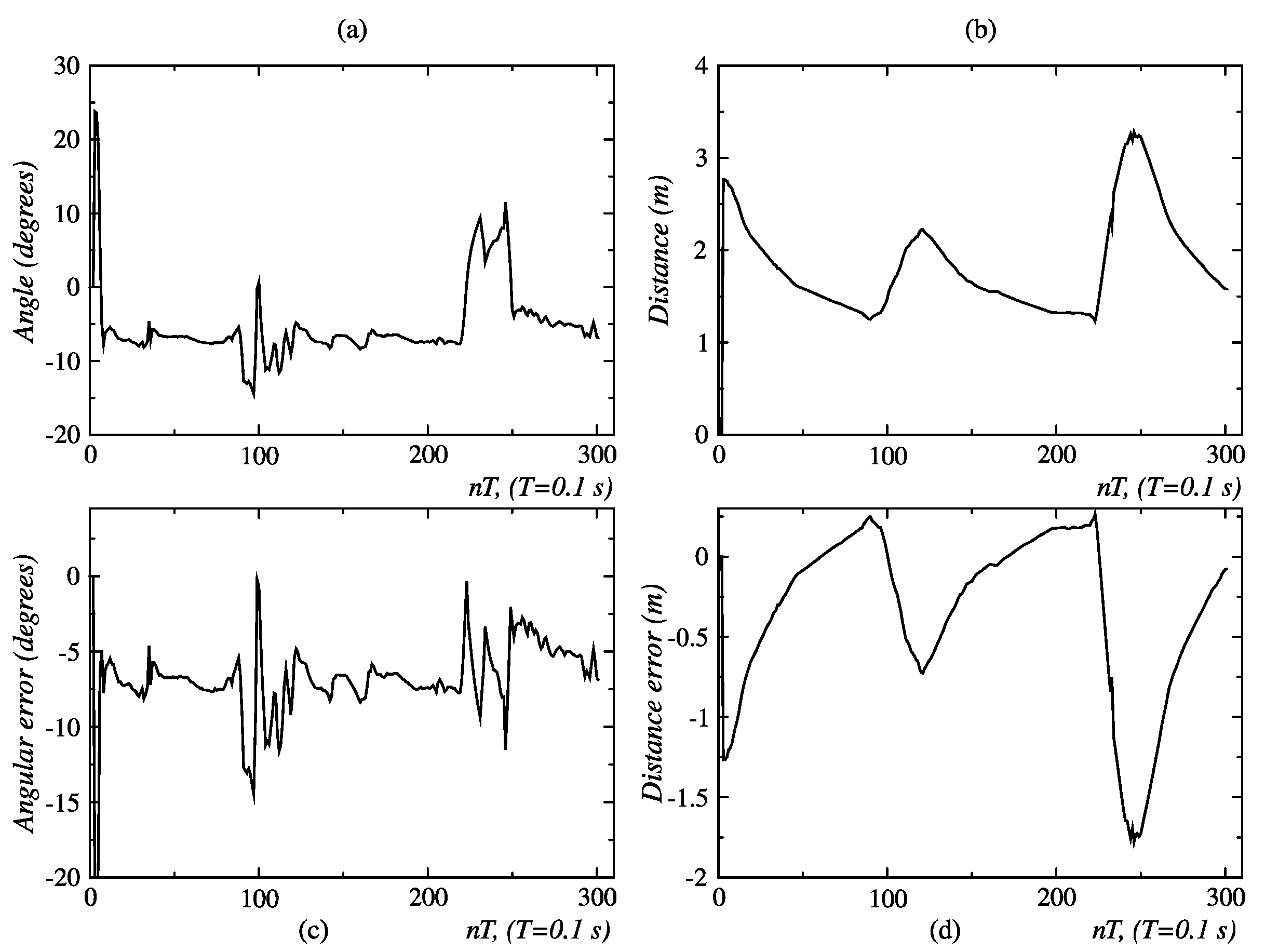
3.2.2. Results for Angular Tracking

Regarding the angular displacement described in Figure 11, as soon as the robot detects that the person is located at 25° (Figure 24), it adjusts its position accordingly to maintain alignment with the person. The error of −25° (Figure 25) is processed by the angular displacement fuzzy behavior, that generates velocity set-points of 60 pp/T (see Figure 26) for both embedded controllers, but with a direction of rotation established according to the third entry of Table 4 input. The final position of 0° degrees is achieved at the end of t = 30 T s. The reference velocities are reduced until they reach a value near zero, when the robot is oriented toward the person.
This value is maintained for a period between t = 16 T s and t = 29 T s. The displacement of person along the arc AC takes place during the period between 30 T and 75 T. Figure 24 shows that, in this lapse of time, the angular measurement deviates from the desired value of 0°. In response to this event, new velocity set-points, between 5 and 15 pp/T, are generated by the angular displacement behavior (Figure 26).
Figure 24 and Figure 25 show that from t = 75 T, the measured angle and the angular position error take a value near 0°. At this point, the person has completed their displacement, stopping at point C. This is also verified by observing Figure 26; the velocity set-points generated by this behavior are near zero from t = 75 T. Since the robot only carried out an angular displacement about its midpoint, the distance to the person did not change significantly, as is shown in Figure 27. Similar results were obtained when the person was moving from right to left, as seen in Figure 28.

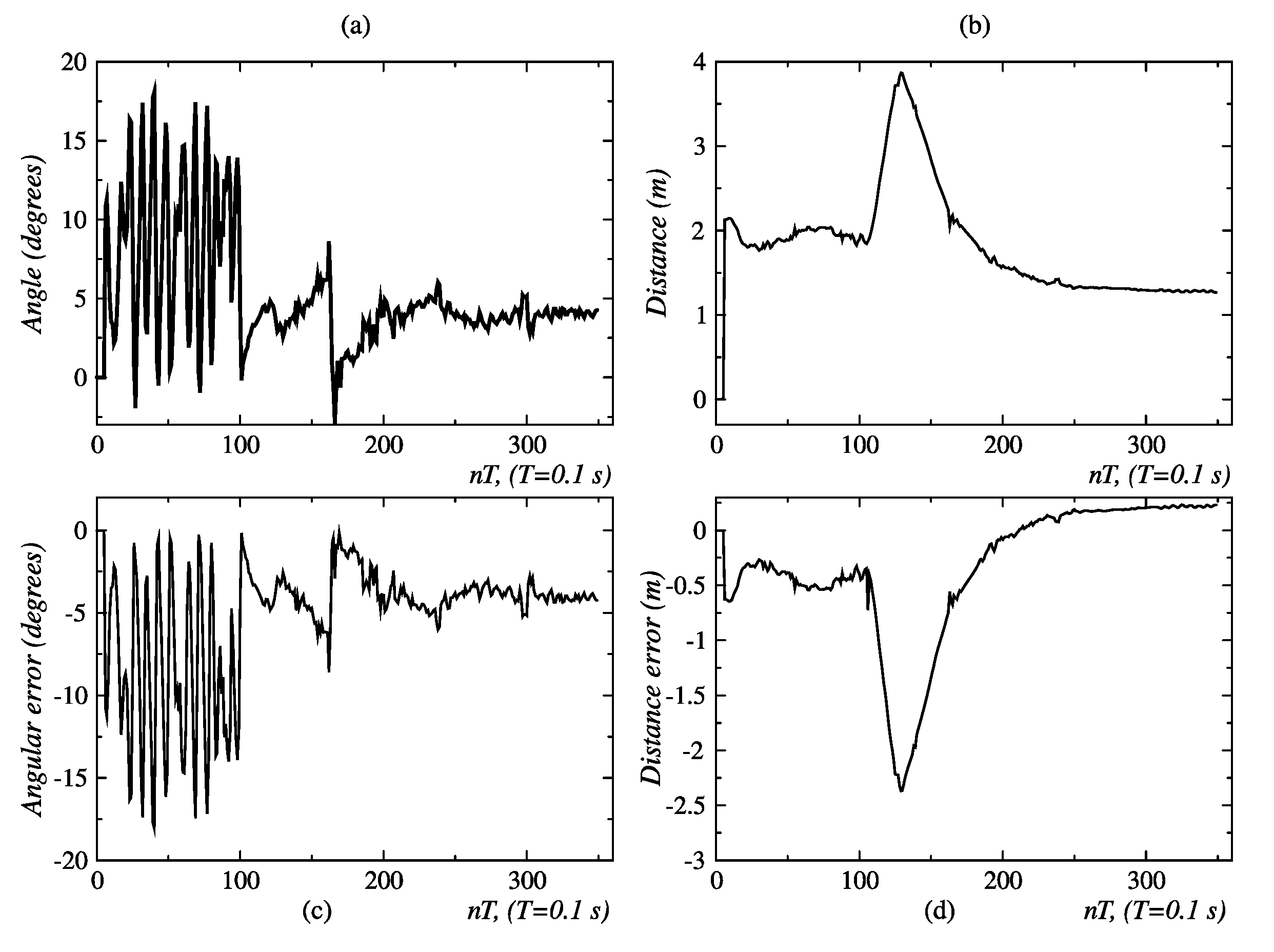
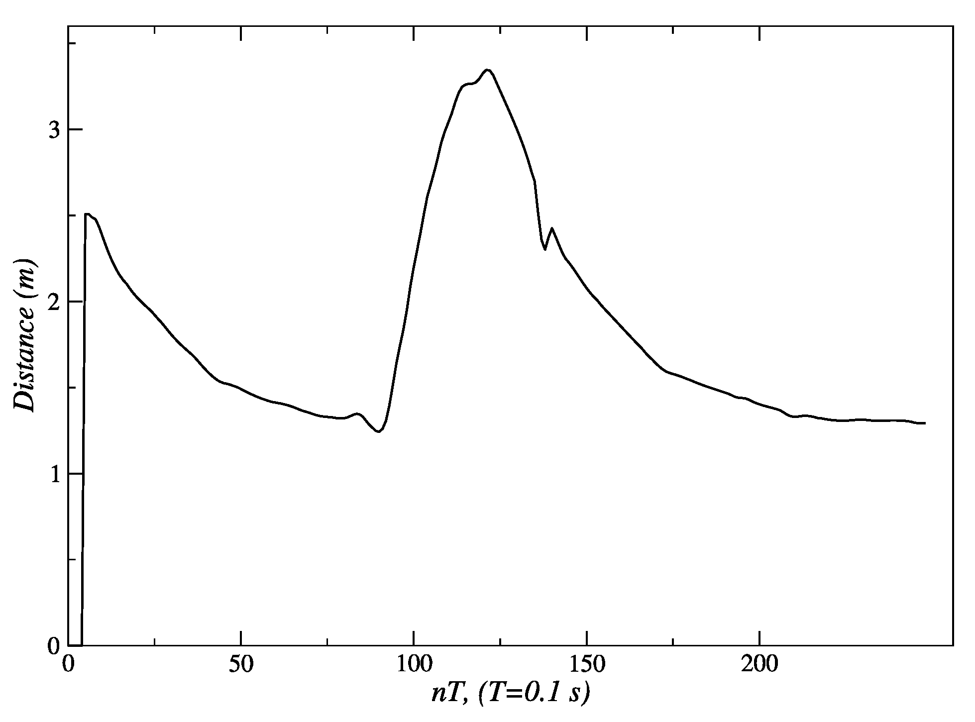
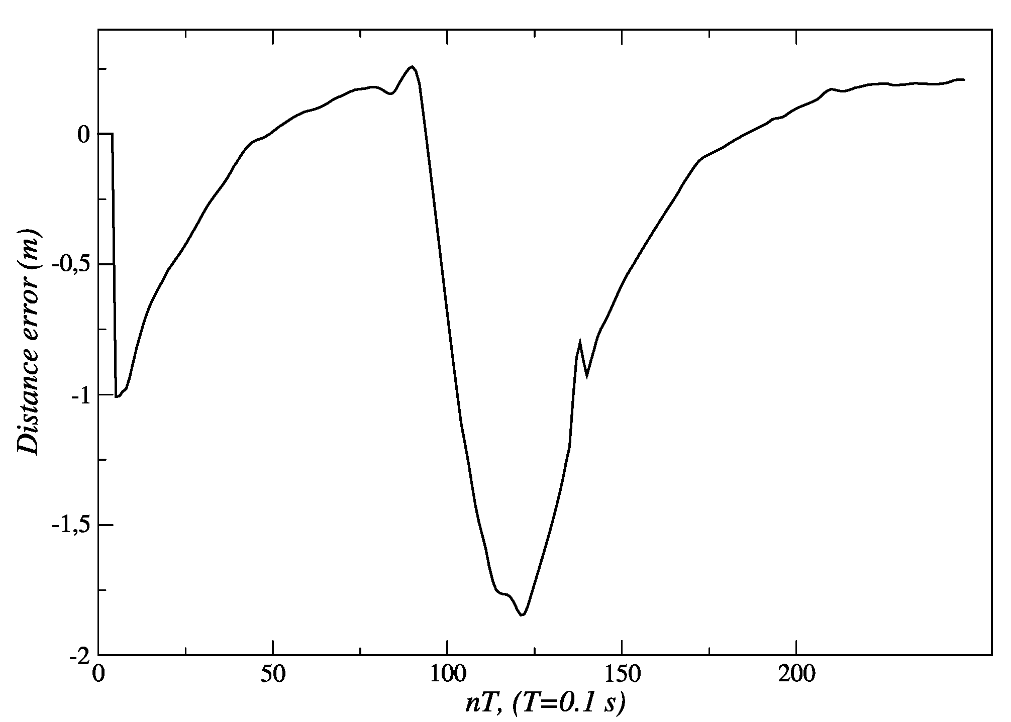
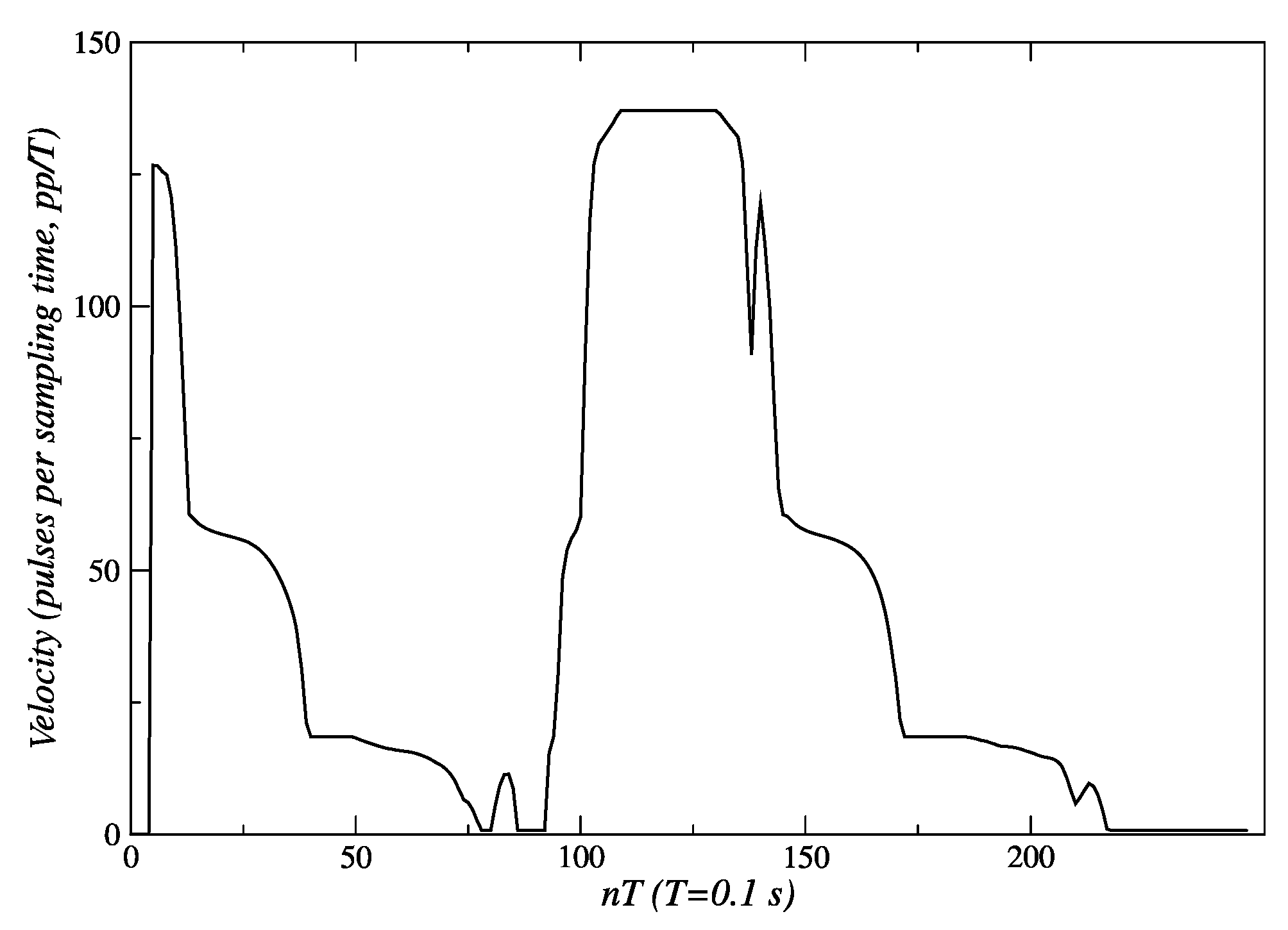
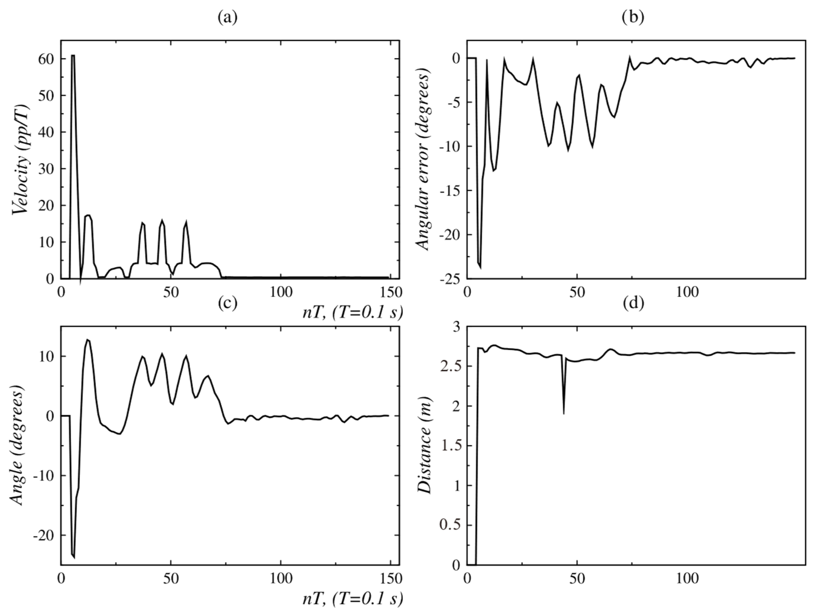
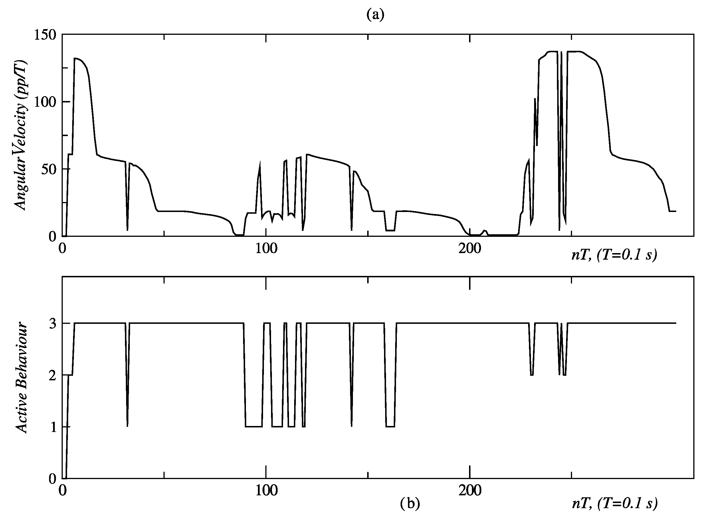
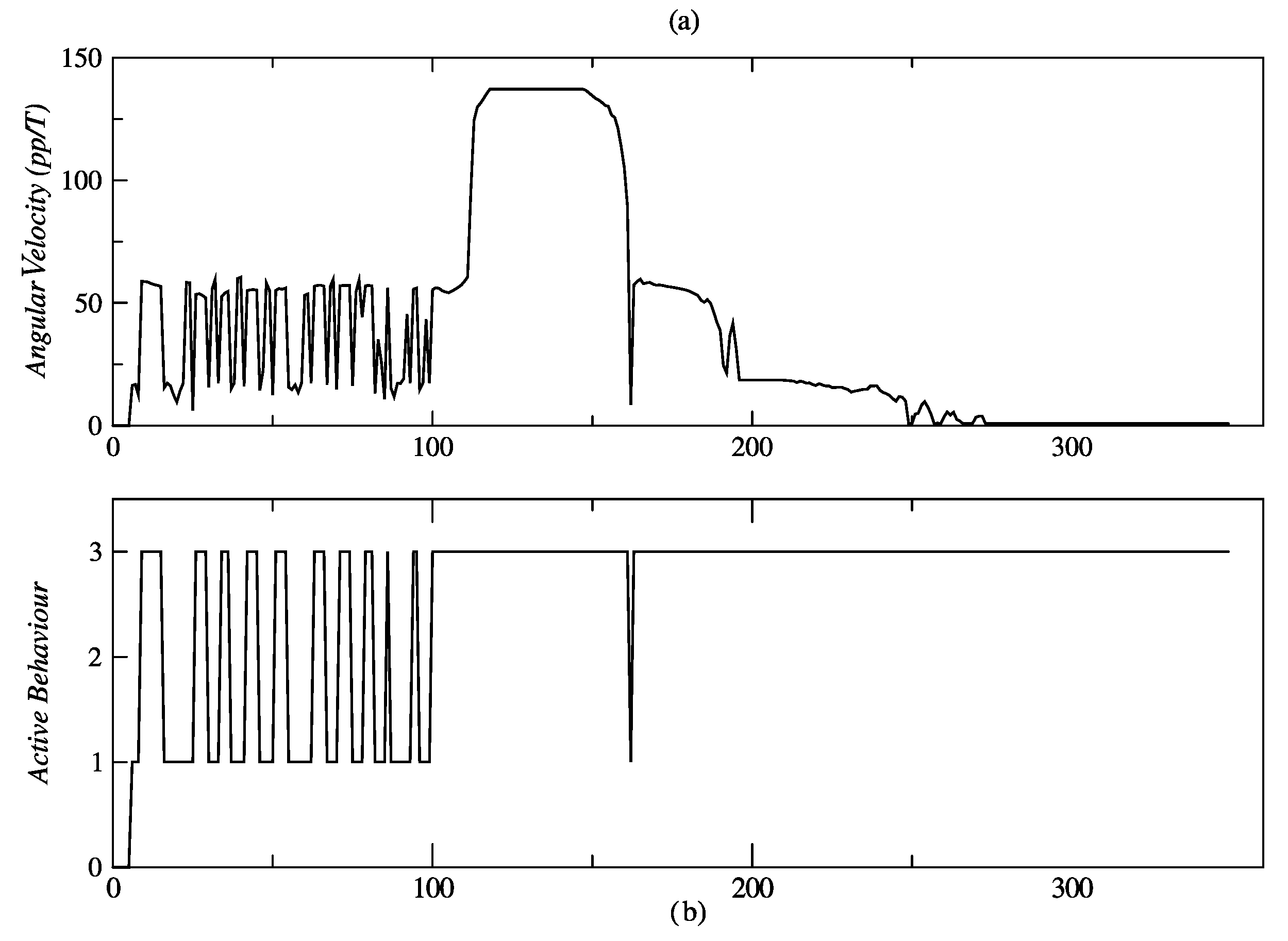
3.3. Results for Behavior Coordination

In the test described by Figure 28, the person initially follows an arc, and then proceeds to make a linear displacement. Figure 29 and Figure 30 show the obtained results of this test. The initial measures of distance and orientation to the person are 2.75 m and 24°, respectively, which are taken at the first sampling periods shown in the same figures. These initial measurements are consistent with the experimental set-up of Figure 29. The behavior-based controller responds to this initial state, by activating the behavior of angular displacement in the CCW direction, which can be seen in Figure 30 marked with the label “2”. The controller sends the same speed set-points (60 pp/T) to both DC motors and commands them to rotate in the CW direction, so that the robot moves in the CCW direction (see Figure 6 and Table 3). After correcting the orientation of the robot and with the person located within the visual field bounded by −8° ≤ ϕ ≤ 8°, it is necessary to correct the distance, for which the behavior of linear displacement is activated up to about t = 90 T (label “3” in Figure 30). At this point, the robot has corrected its location relative to the person, who has remained motionless at point A. Then, the person begins their displacement along the arc AC, and the fuzzy controller responds to this with multiple switching events between behaviors “1” (angular displacement in the CW direction) and “3” (linear forward displacement), the first of which is activated for longer. This switching is maintained between t = 90 T s and t = 120 T s, allowing the robot to follow the person without losing them.
At t = 120 T s, the person is already at point C and initiates their route along the line segment CD. Figure 30 shows how from this moment, the behavior that remains most active is “3” (linear displacement), with sporadic activations of “1” (angular displacement in the CW direction) and “2” (angular displacement in the CCW direction) behaviors. Thus, it ensures that the person remains “visible” to the robot.
In the second behavior coordination test described in Figure 12, the person traces a full circle and then moves away linearly. The initial values of angular position and distance, measured with the Kinect sensor, are ϕ = 11.2° and d = 2.1 m, respectively; this is shown in Figure 31a and Figure 13b. During the movement of the person along the circumference, between points A and B, no significant changes are seen in the distance (Figure 29b), but changes were repeatedly seen in the angular position (Figure 29a). The circular displacement of the person occurs within 0 ≤ t ≤ 100 T, a period during which repetitive changes are observed in speed set-points (Figure 30a,b) and permanent switching between the behaviors of angular displacement in the CW direction and linear displacement occurs to correct the orientation and distance of the robot (Figure 30b). This happens until the person reaches point B, from which starts a linear displacement over the straight line BC.
Once the person begins to move away from the robot, the behavior of linear displacement takes control of the robot’s effectors and sends a set-point of speed of about 138 pp/T within 120 Tt ≤ 150 T.
The value of these set-points decreases as the robot reduces its distance from the person, until it reaches zero for t ≥ 270 T, as is shown in Figure 29b. As can be seen in Figure 31a, the behavior that remains most active for t ≥ 100 T is the linear displacement “3”, which it is consistent with the displacement of the person between points B and C.
Finally, it is seen in Figure 29d that after 270 T, the distance error is about 0.25 m, with which the robot approaches the person and stops at a near distance of 1.25 m. The final angular orientation error is near 4.5°, as shown in Figure 29c.
According to the results shown, the proposed architecture provides a balance between efficiency and robustness. By focusing on depth data and adaptable fuzzy rules, the system is ideal for low-cost platforms with limited computational resources. In comparison, alternative methods often involve complex techniques. For instance, feature fusion (e.g., facial recognition and clothing texture), as explored in [37,38], improves precision but demands high computational resources. Other methods rely on wearable devices like infrared LEDs or ultrasonic transmitters, which increase costs and limit flexibility. Deep learning methods, such as SSD (Single Shot MultiBox Detector, a deep learning method designed for real-time object detection in images), ensure robust detection but require specialized hardware like GPUs, elevating system complexity. In contrast, our proposed architecture stands out for its simplicity and efficiency, maintaining precise, adaptable control without requiring advanced hardware or intensive computations. This practical approach is well suited for applications constrained by economic and computational limitations.

4. Conclusions

This research presented a comprehensive approach to the design and implementation of a lightweight two-layer control architecture for a human-following robot, optimized for environments with limited computational resources. By combining a fuzzy behavior-based control system with low-level embedded controllers, the robot effectively tracks a human subject in real time while maintaining a safe distance of approximately 1.3 m. Although the skeletal tracking functionality of the Kinect sensor allows for the recovery of the human target in occlusion conditions, such occlusions were not incorporated in the experiments conducted in this work, which could be considered as future work. The system leverages an RGB-D sensor for precise distance and angular measurements, allowing for seamless human–robot interaction in indoor environments.
Experimental validation confirmed the robustness and effectiveness of the proposed architecture. The internal model control (IMC) method, employed in the low-level control layer, demonstrated superior performance. For the left and right motors, IMC achieved an Integral of Absolute Error (IAE) of 303 and 301, respectively, compared to 553 and 549 obtained with the pole placement method. Similarly, the Integral of Squared Error (ISE) values for IMC were 31,561 and 31,443 for the left and right motors, respectively, while pole placement yielded 48,955 and 47,855. These metrics indicate that IMC offers significantly better performance, making it the preferred choice for the low-level control layer of the proposed architecture. The fuzzy behavior-based control at the high level ensured fast response times and the flexible handling of complex navigation tasks, such as adjusting for sudden changes in human orientation. These results emphasize the system’s capability to provide reliable human-following behavior, making it well suited for assistive robotic applications where real-time responsiveness and safety are critical. In the linear displacement experiments, the robot successfully followed the person until reaching the safety and comfort distance of approximately 1.3 m (Figure 8 and Figure 18). For angular displacement, the robot achieved an orientation error of less than 1° relative to the person being followed during the movement, as shown in Figure 24 and Figure 25. This result is highly acceptable, as it keeps the person centered within the depth sensor’s field of view. However, this error increased to a magnitude of 4.5° as the final orientation in the experiments involving the coordination of fuzzy behaviors. Although this increase is larger compared to the angular displacement experiments, it remains a highly acceptable value for human-following applications.
A key advantage of this architecture is its modularity and scalability. These design principles allow for easy adaptation and future enhancements, including the integration of additional sensors, new behaviors, or the application of the system to a broader range of assistive tasks. This flexibility makes it a highly adaptable solution for various personal assistance scenarios, such as aiding the elderly or individuals with disabilities.
Potential future directions for this work include refining the system’s ability to operate in more dynamic and unpredictable environments. Incorporating machine learning algorithms for human behavior prediction and trajectory planning could further improve the robot’s ability to manage complex interactions. Additionally, optimizing the computational load of the control architecture would enable its deployment on even more resource-constrained robotic platforms, broadening its applicability across diverse domains.
The development and validation of the Carlitos-Care platform represent a significant advancement in the field of assistive robotics. The system not only addresses critical challenges in human-following tasks but also provides a scalable and cost-effective solution for enhancing personal assistance technology. This research sets a strong foundation for future innovations in autonomous robots designed to improve the quality of life for individuals requiring assistance in their daily activities.

Author Contributions

Conceptualization, G.A.A.-A. and J.A.J.-B.; methodology, G.A.A.-A. and J.A.J.-B.; software, G.A.A.-A.; validation, G.A.A.-A., D.A.M.-M. and J.A.J.-B.; formal analysis, G.A.A.-A. and J.A.J.-B.; investigation, G.A.A.-A.; resources, J.A.J.-B.; data curation, G.A.A.-A., D.A.M.-M. and J.A.J.-B.; writing—original draft preparation, G.A.A.-A. and J.A.J.-B.; writing—review and editing, G.A.A.-A. and J.A.J.-B.; visualization, G.A.A.-A., D.A.M.-M. and J.A.J.-B.; supervision, J.A.J.-B.; project administration, G.A.A.-A. and J.A.J.-B.; funding acquisition, J.A.J.-B. All authors have read and agreed to the published version of the manuscript.

Funding

This research received no external funding. The APC was funded by the authors.

Institutional Review Board Statement

Not applicable.

Informed Consent Statement

Not applicable.

Data Availability Statement

The data presented in this study are available upon request from the corresponding authors.

Acknowledgments

The authors express their gratitude to Politécnico Colombiano Jaime Isaza Cadavid for the materials and supports received to carry out the respective experiments.

Conflicts of Interest

The authors declare no conflicts of interest.

References

  1. Fulmer, T.; Reuben, D.B.; Auerbach, J.; Fick, D.M.; Galambos, C.; Johnson, K.S. Actualizing better health and health care for older adults: Commentary describes six vital directions to improve the care and quality of life for all older Americans. Health Aff. 2021, 40, 219–225. [Google Scholar] [CrossRef] [PubMed]
  2. Aggar, C.; Sorwar, G.; Seton, C.; Penman, O.; Ward, A. Smart home technology to support older people’s quality of life: A longitudinal pilot study. Int. J. Older People Nurs. 2023, 18, e12489. [Google Scholar] [CrossRef] [PubMed]
  3. Sather, R.; Soufineyestani, M.; Imtiaz, N.; Khan, A.A. Assistive robots designed for elderly care and caregivers. Int. J. Robot. Control 2021, 3, 1–12. [Google Scholar] [CrossRef]
  4. Sharma, N.; Pandey, J.K.; Mondal, S. A review of mobile robots: Applications and future prospect. Int. J. Precis. Eng. Manuf. 2023, 24, 1695–1706. [Google Scholar] [CrossRef]
  5. Keroglou, C.; Kansizoglou, I.; Michailidis, P.; Oikonomou, K.M.; Papapetros, I.T.; Dragkola, P.; Michailidis, I.; Gasteratos, A.; Kosmatopoulos, E.; Sirakoulis, G.C. A survey on technical challenges of assistive robotics for elder people in domestic environments: The ASPiDA concept. IEEE Trans. Med. Robot. Bionics 2023, 5, 196–205. [Google Scholar] [CrossRef]
  6. Johnston, C. Ethical design and use of robotic care of the elderly. J. Bioethical Inq. 2022, 19, 11–14. [Google Scholar] [CrossRef]
  7. Cai, S.; Ram, A.; Gou, Z.; Shaikh, M.A.W.; Chen, Y.A.; Wan, Y.; Hara, K.; Zhao, S.; Hsu, D. Navigating real-world challenges: A quadruped robot guiding system for visually impaired people in diverse environments. In Proceedings of the CHI Conference on Human Factors in Computing Systems, Honolulu, HI, USA, 11–16 May 2024; pp. 1–18. [Google Scholar] [CrossRef]
  8. Asgharian, P.; Panchea, A.M.; Ferland, F. A review on the use of mobile service robots in elderly care. Robotics 2022, 11, 127. [Google Scholar] [CrossRef]
  9. Calatrava, F.M.; Gutiérrez, E.; Bautista, D.; Ortiz, F.J.; González, J.R.; Vera, J.A.; Jiménez, M.; Méndez, I.; Ruiz, C.; Mozos, O.M. Robotic-based well-being monitoring and coaching system for the elderly in their daily activities. Sensors 2021, 21, 6865. [Google Scholar] [CrossRef]
  10. Abou, A.; Wang, M.; Padır, T. A systematic review of robotics research in support of in-home care for older adults. Information 2020, 11, 75. [Google Scholar] [CrossRef]
  11. Zhao, D.; Sun, X.; Shan, B.; Yang, Z.; Yang, J.; Liu, H.; Jiang, Y.; Hiroshi, Y. Research status of elderly-care robots and safe human-robot interaction methods. Front. Neurosci. 2023, 17, 1291682. [Google Scholar] [CrossRef]
  12. Kok, C.L.; Ho, C.K.; Teo, T.H.; Kato, K.; Koh, Y.Y. A novel implementation of a social robot for sustainable human engagement in homecare services for ageing populations. Sensors 2024, 24, 4466. [Google Scholar] [CrossRef] [PubMed]
  13. Liao, Y.J.; Jao, Y.L.; Boltz, M.; Adekeye, O.T.; Berish, D.; Yuan, F.; Zhao, X. Use of a humanoid robot in supporting dementia care: A qualitative analysis. SAGE Open Nurs. 2023, 9, 23779608231179528. [Google Scholar] [CrossRef] [PubMed]
  14. Sugianto, N.; Tjondronegoro, D.; Stockdale, R.; Yuwono, E.I. Privacy-preserving AI-enabled video surveillance for social distancing: Responsible design and deployment for public spaces. Inf. Technol. People 2024, 37, 998–1022. [Google Scholar] [CrossRef]
  15. Ravi, S.; Climent-Pérez, P.; Florez, F. A review on visual privacy preservation techniques for active and assisted living. Multimed. Tools Appl. 2024, 83, 14715–14755. [Google Scholar] [CrossRef]
  16. Varshney, N.; Bakariya, B.; Kushwaha, A.K.; Khare, M. Rule-based multi-view human activity recognition system in real time using skeleton data from RGB-D sensor. Soft Comput. 2023, 27, 405–421. [Google Scholar] [CrossRef]
  17. Mollaei, H.; Sepehri, M.; Khatibi, T. Patient’s actions recognition in hospital’s recovery department based on RGB-D dataset. Multimed. Tools Appl. 2023, 82, 24127–24154. [Google Scholar] [CrossRef]
  18. Patel, I.; Kulkarni, M.; Mehendale, N. Review of sensor-driven assistive device technologies for enhancing navigation for the visually impaired. Multimed. Tools Appl. 2024, 83, 52171–52195. [Google Scholar] [CrossRef]
  19. Van Assche, M.; Petrovic, M.; Cambier, D.; Calders, P.; Van Gelder, P.; Van de Velde, D. The perspectives of older adults with mild cognitive impairment and their caregivers on the use of socially assistive robots in healthcare: Exploring factors that influence attitude in a pre-implementation stage. Disabil. Rehabil. Assist. Technol. 2024, 19, 222–232. [Google Scholar] [CrossRef]
  20. Petrich, L.C. Advancing the Acceptance and Use of Wheelchair-Mounted Robotic Manipulators. Master of Science Thesis, Department of Computing Science, University of Alberta, Edmonton, Canada, 2023. [Google Scholar]
  21. Wu, D.; Pu, L.; Jo, J.; Hexel, R.; Moyle, W. Deploying robot-led activities for people with dementia at aged care facilities: A feasibility study. J. Am. Med. Dir. Assoc. 2024, 25, 105028. [Google Scholar] [CrossRef]
  22. Terayama, J.; Ravankar, A.A.; Luces, J.V.; Tafrishi, S.A.; Hirata, Y. Concept and prototype development of adaptive touch walking support robot for maximizing human physical potential. IEEE Robot. Autom. Lett. 2024, 9, 6935–6942. [Google Scholar] [CrossRef]
  23. Zhang, J.; Huang, Y.; Peng, F.; Yao, Y. Pole placement-based current control method for CSI-fed PMSM drive with eliminating capacitor voltage sampling. IEEE Trans. Power Electron. 2023, 38, 9409–9420. [Google Scholar] [CrossRef]
  24. Della, C.; Duriez, C.; Rus, D. Model-based control of soft robots: A survey of the state of the art and open challenges. IEEE Control Syst. Mag. 2023, 43, 30–65. [Google Scholar] [CrossRef]
  25. Shoshany, S.; Peleg, E.; Zonnenshain, A.; Yudilevitch, G. Model-based-systems-engineering for conceptual design: An integrative approach. Syst. Eng. 2023, 26, 783–799. [Google Scholar] [CrossRef]
  26. De Vries, P.C.; Cinque, M.; De Tommasi, G.; Treutterer, W.; Humphreys, D.; Walker, M.; Felici, F.; Gomez, I.; Zabeo, L.; Ravensbergen, T.; et al. Strategy to systematically design and deploy the ITER plasma control system: A system engineering and model-based design approach. Fusion Eng. Des. 2024, 204, 114464. [Google Scholar] [CrossRef]
  27. Mongeau, J.M.; Yang, Y.; Escalante, I.; Cowan, N.; Jayaram, K. Moving in an uncertain world: Robust and adaptive control of locomotion from organisms to machine intelligence. Integr. Comp. Biol. 2024, 64, 1390–1407. [Google Scholar] [CrossRef]
  28. Lesire, C.; Bailon, R.; Barbier, M.; Grand, C. A hierarchical deliberative architecture framework based on goal decomposition. In Proceedings of the 2022 IEEE/RSJ International Conference on Intelligent Robots and Systems (IROS), Kyoto, Japan, 23–27 October 2022; pp. 9865–9870. [Google Scholar] [CrossRef]
  29. Ju, C.; Son, H. A hybrid systems-based hierarchical control architecture for heterogeneous field robot teams. IEEE Trans. Cybern. 2021, 53, 1802–1815. [Google Scholar] [CrossRef]
  30. Burgess, B.; Lehnert, C.; Leitner, J.; Corke, P. An architecture for reactive mobile manipulation on-the-moveIn. In Proceedings of the 2023 IEEE International Conference on Robotics and Automation (ICRA), London, UK, 29 May 2023–2 June 2023; pp. 1623–1629. [Google Scholar] [CrossRef]
  31. Akkaladevi, S.C.; Propst, M.; Deshpande, K.; Hofmann, M.; Pichler, A. Towards a behavior tree based robotic skill execution framework for human robot collaboration in industrial assembly. In Proceedings of the IEEE International Conference on Automation, Robotics and Applications (ICARA), Athens, Greece, 22–24 February 2024; pp. 18–22. [Google Scholar] [CrossRef]
  32. Raja, R. Software architecture for agricultural robots: Systems, requirements, challenges, case studies, and future perspectives. IEEE Trans. AgriFood Electron. 2024, 2, 125–137. [Google Scholar] [CrossRef]
  33. Ohlander, H.; Johnson, D. Path Planning and Collision Avoidance for a 6-DOF Manipulator: A Comparative Study of Path Planning and Collision Avoidance Algorithms for the Saab Seaeye eM1-7 Electric Manipulator. Master’s Thesis, Department of Electrical Engineering, Linköping University, Linköping, Sweden, 2024. [Google Scholar]
  34. Naderolasli, A.; Shojaei, K.; Chatraei, A. Leader-follower formation control of Euler-Lagrange systems with limited field-of-view and saturating actuators: A case study for tractor-trailer wheeled mobile robots. Eur. J. Control 2024, 75, 100903. [Google Scholar] [CrossRef]
  35. Hussey, S.; Swindell, J.E.; Goad, A.C.; Egbert, A.; Clegg, A.; Baylis, C.; Marks, R.J. Application of Mamdani fuzzy inference systems to interference assessments. In Proceedings of the IEEE International Symposium on Dynamic Spectrum Access Networks (DySPAN), Washington, DC, USA, 13–16 May 2024; pp. 13–18. [Google Scholar] [CrossRef]
  36. Vásconez, J.P.; Calderón, M.; Briceño, I.C.; Pantoja, J.M.; Cruz, P.J. A behavior-based fuzzy control system for mobile robot navigation: Design and assessment. In Proceedings of the International Conference on Advanced Research in Technologies, Information, Innovation and Sustainability, Madrid, Spain, 18–20 October 2023; Springer Nature Switzerland: Cham, Switzerland, 2024; pp. 412–426. [Google Scholar]
  37. Algabri, A.J.; Choi, M.T. Deep-learning-based indoor human following of mobile robot using color feature. Sensors 2020, 20, 2699. [Google Scholar] [CrossRef]
  38. Jeyatharan, K.; Ekanayake, H.; Sandaruwan, K.D. Behavior based tracking for human following robot. In Proceedings of the 2021 IEEE 16th International Conference on Industrial and Information Systems (ICIIS), Kandy, Sri Lanka, 09–11 December 2021; pp. 371–376. [Google Scholar] [CrossRef]
Figure 1. Block diagram representation and physical appearance of Carlitos-Care mobile robotic platform. Wireless communication is provided by an 802.15.4 XBee module. Source: Authors.
Sensors 24 07796 g001
Figure 2. (a) robot effector response to a (b) time-variant duty-cycle PWM control signal (b). Source: Authors.
Sensors 24 07796 g002
Figure 3. Low-level control layer implemented in the MCF51QE128-embedded system by means a couple of PI discrete-time controllers. Source: Authors.
Sensors 24 07796 g003
Figure 4. Skeletal joints and coordinate system of the Kinect sensor. For the follow-up of people, we isolate the articulation number 1. Source: Authors.
Sensors 24 07796 g004
Figure 5. Fuzzy membership functions for LDFB and ADFB. Source: Authors.
Sensors 24 07796 g005
Figure 6. Control of movements in a differential robot. When the motor speeds are equal in magnitude, either pure linear or angular displacement can be achieved by controlling the direction of motor rotation. Source: Authors.
Sensors 24 07796 g006
Figure 7. Proposed two-level control architecture BSM scheme. Source: Authors.
Sensors 24 07796 g007
Figure 8. Linear displacement behavior: the robot approaches a person standing. Source: Authors.
Sensors 24 07796 g008
Figure 9. Linear displacement behavior: the robot approaches a person standing and follows them. Source: Authors.
Sensors 24 07796 g009
Figure 10. Angular displacement behavior: the robot makes an angular displacement (left to right) that maintains the person in the center of the scene. Source: Authors.
Sensors 24 07796 g010
Figure 11. Behaviors coordination: the robot first makes an angular displacement and then a linear displacement. Source: Authors.
Sensors 24 07796 g011
Figure 12. Complete circle displacement and linear displacement test. Source: Authors.
Sensors 24 07796 g012
Figure 13. Angle distances and errors related to circular and linear displacement, detailing: (a) the angle between the person and the robot, (b) their separating distance, (c) the angular error (deviation from the desired orientation), and (d) the distance error (difference from the desired position). Source: Authors.
Sensors 24 07796 g013
Figure 14. PPC responses of the right and left motors to a set-point of 100 pp/T. Source: Authors.
Sensors 24 07796 g014
Figure 15. IMC responses of the right and left motors to a set-point of 100 pp/T. Source: Authors.
Sensors 24 07796 g015
Figure 16. PPC responses of the right and left motors to a set-point of 150 pp/T. Source: Authors.
Sensors 24 07796 g016
Figure 17. IMC responses of the right and left motors to a set-point of 150 pp/T. Source: Authors.
Sensors 24 07796 g017
Figure 18. Distance measured by the Kinect during the linear displacement of the person. Source: Authors.
Sensors 24 07796 g018
Figure 19. Distance error measured by the Kinect during the linear displacement of the person. Source: Authors.
Sensors 24 07796 g019
Figure 20. Velocity references sent to the actuators of the robot. Source: Authors.
Sensors 24 07796 g020
Figure 21. Distance between the robot and a person initially standing and then being followed. Source: Authors.
Sensors 24 07796 g021
Figure 22. Distance error between the robot and a person initially standing and then being followed. Source: Authors.
Sensors 24 07796 g022
Figure 23. Velocity set-points are sent to the actuators of the robot for the linear following of persons. Source: Authors.
Sensors 24 07796 g023
Figure 24. Angular displacement behavior: the robot makes an angular displacement (right to left) that maintains the person in the center of the scene. Source: Authors.
Sensors 24 07796 g024
Figure 25. Angular displacement error: the robot makes an angular displacement (right to left) that maintains the person in the center of the scene. Source: Authors.
Sensors 24 07796 g025
Figure 26. Velocity angular behavior: the robot makes an angular displacement (right to left) that maintains the person in the center of the scene. Source: Authors.
Sensors 24 07796 g026
Figure 27. Distance to the person during the angular displacement. Source: Authors.
Sensors 24 07796 g027
Figure 28. Angular displacement behavior: the robot makes an angular displacement (right to left) that maintains the person in the center of the scene, showing: (a) speed, (b) angular error, (c) angle, and (d) distance. Source: Authors.
Sensors 24 07796 g028
Figure 29. Angles, distances, and errors related to the arc of the person walking away, detailing: (a) angles, (b) distance, (c) angular error, and (d) distance error. Source: Authors.
Sensors 24 07796 g029
Figure 30. Angular velocity and active behavior related to the arc of the person walking away, showing: (a) angular velocity, and (b) active behavior. Source: Authors.
Sensors 24 07796 g030
Figure 31. Angular velocity and active behavior related to circular and linear displacement, showing: (a) angular velocity, and (b) active behavior. Source: Authors.
Sensors 24 07796 g031
Table 1. Variables associated with FIS controllers. Source: Authors.
BehaviorInput VariableOutput Variable
Linear displacemented: distance error between person and robotSpeed references for IMC
Angular displacementea: angular error between person and robotSpeed references for IMC
Table 2. LDFB characterization. Source: Authors.
Input: Distance Error (ed)Output: Angular Speed of Wheels (ω)
U = {ed ∈ ℝ | −2.3 ≤ ed ≤ 0.7}
T(ed) = {nde, nmde, zde, pde}
G: Prefixes:
  n: negative, m: medium
  z: zero, p: positive
 Suffixes:
  de: distance error
V = {ω ∈ ℝ | 0 ≤ ω ≤ 220}
T(ω) = {rsl, rslm, rshm, rsh}
G: Prefixes:
  rs: references of speed
Suffixes:
  l: low, m: medium
  h: high
M:
  nde → trapmf [−2.3, −2.3, −1.085, −0.739]
  nmde → trimf [−1.48, −0.6558, −0.117]
  zde → trimf [−0.713, 0, 0.177]
  pde → trapmf [0, 0.12, 0.7, 0.7]
M:
   rsl → trimf [0, 0, 4.47]
   rslm → trimf [1.18, 17.63, 36.9]
   rshm → trimf [21, 36.43, 124]
   rsh → trapmf [47.7, 58.53, 220, 220]
Table 3. Driving of motors for rotating the robot. Source: Authors.
Left MotorRight MotorRobot Displacement
CCWCWLinear forward
CWCCWLinear back
CWCWCCW
CCWCCWCW
Table 4. ADFB characterization. Source: Authors.
Input: Error Angle (ea)Output: Reference Velocity for Angular Displacement (vra)
U = {ea ∈ ℝ | −28 ≤ ea ≤ 0}
T(ea) = {eanh, eanm, eanl, eaze}
G: Prefixes:
   ea: error angle
  Suffixes:
   n: negative, m: medium
   ze: zero, h: high, l: low
V = {vra ∈ ℝ | 0 ≤ vra ≤ 100}
T(vra) = {rsze, rspl, rspm, rsph}
G: Prefixes:
   rs: references of speed
Suffixes:
   l: low, m: medium
   h: high, p: positive, ze: zero
M:
   eanh → trapmf [−28, −28, −15.88, −13.4]
   eanm → trimf [−18.3, −12.24, −8.41]
   eanl → trimf [−11.9, −6.073, −1.77]
   eaze → trapmf [−5.71, 0.0299, 0, 0]
M:
  rsze → trimf [0, 0.534, 1.603]
   rspl → trimf [0.748, 3.95, 8.013]
  rspm → trimf [5.02, 15.92, 30.9]
  rsph → trapmf [20, 22.33, 100, 100]
Table 5. Performance indexes of PPC and IMC. Source: Authors.
Left IAEMotor ISERight IAEMotor ISE
Pole Placement55348,95554947,855
Internal Model30331,56130131,443
Disclaimer/Publisher’s Note: The statements, opinions and data contained in all publications are solely those of the individual author(s) and contributor(s) and not of MDPI and/or the editor(s). MDPI and/or the editor(s) disclaim responsibility for any injury to people or property resulting from any ideas, methods, instructions or products referred to in the content.

