Position-Constrained Calibration Compensation for Hand–Eye Calibration in Industrial Robots


Abstract
1. Introduction
2. Hand–Eye Calibration of the Line Structure Light Sensor
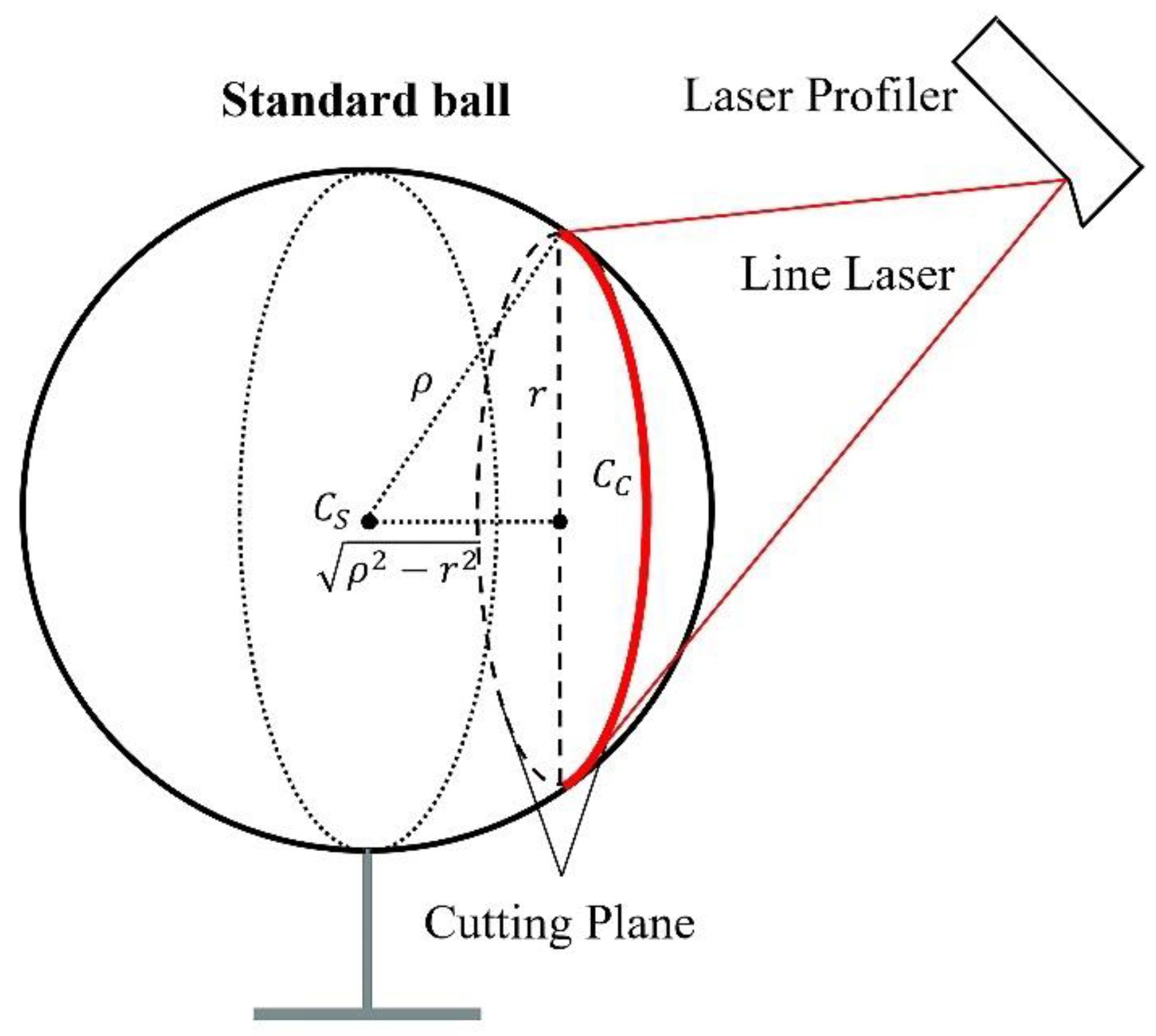
2.1. Principle of the Hand–Eye Calibration Algorithm Based on Spherical Constraints
2.2. Position-Constrained Calibration Compensation Algorithm
3. Experimental Verification and Results Analysis
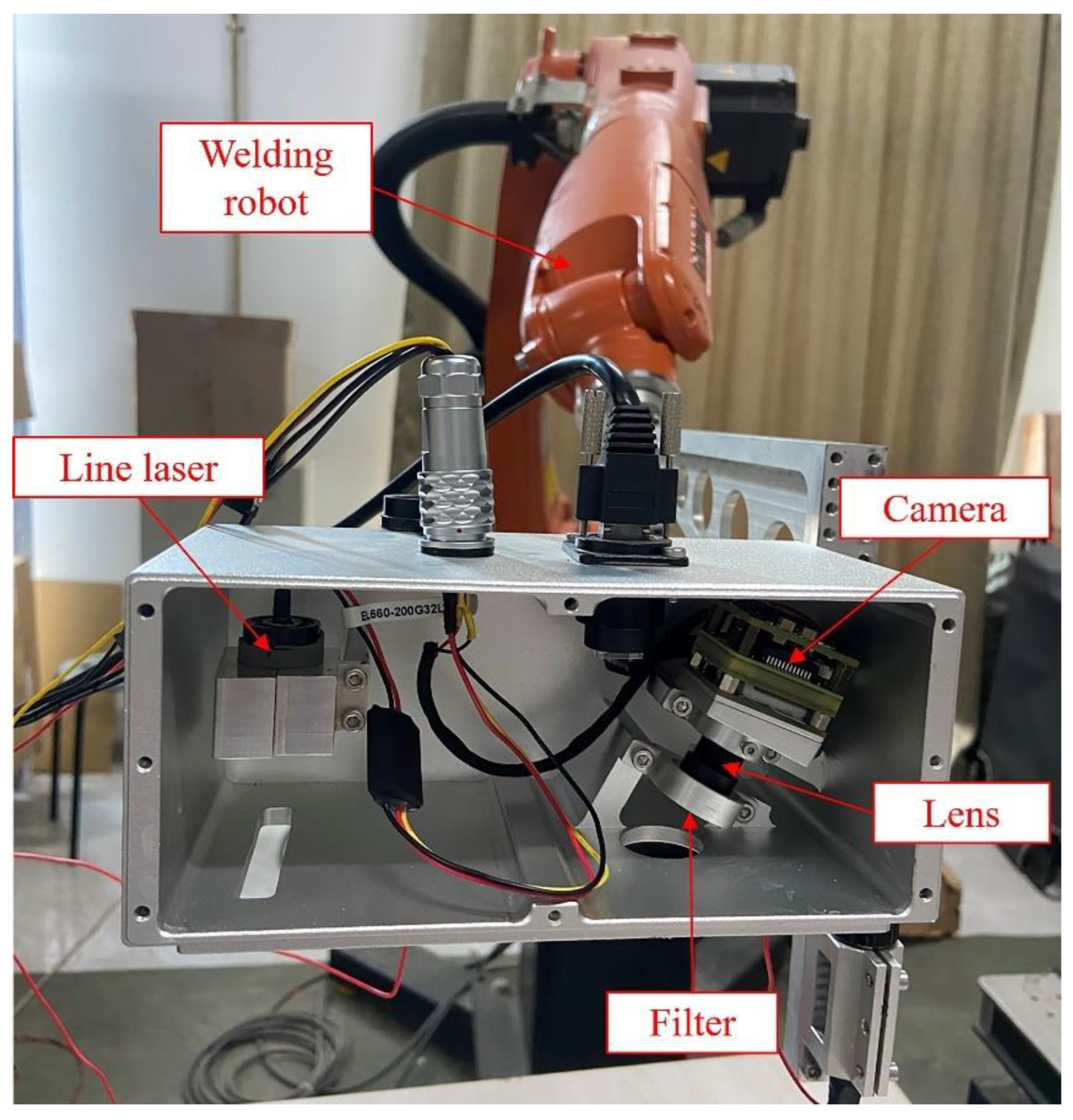
3.1. Experimental Setup
3.2. Hand–Eye Calibration Experiment
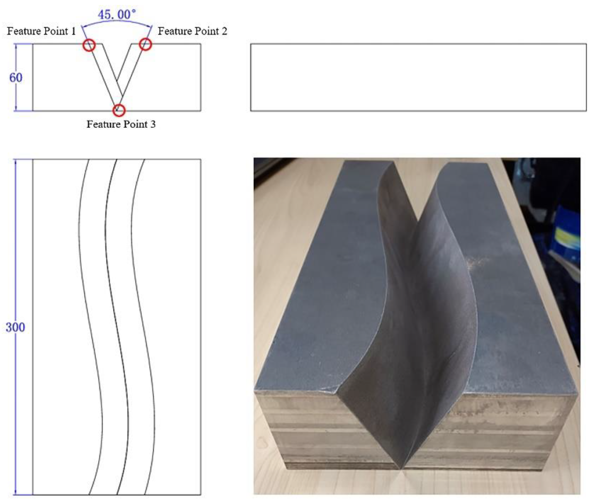
3.3. Three-Dimensional Reconstruction Accuracy Verification
4. Conclusions
Author Contributions
Funding
Institutional Review Board Statement
Informed Consent Statement
Data Availability Statement
Conflicts of Interest
References
- Pietraszkiewicz, W.; Konopińska, V. Junctions in shell structures: A review. Thin-Walled Struct. 2015, 95, 310–334. [Google Scholar] [CrossRef]
- Wu, Q.; Li, Z.; Gao, C.; Biao, W.; Shen, G. Research on welding guidance system of intelligent perception for steel weldment. IEEE Sens. J. 2023, 23, 5220–5231. [Google Scholar] [CrossRef]
- Wang, X.; Zhou, X.; Xia, Z.; Gu, X. A survey of welding robot intelligent path optimization. J. Manuf. Process. 2021, 63, 14–23. [Google Scholar] [CrossRef]
- Guan, T. Research on the application of robot welding technology in modern architecture. Int. J. Syst. Assur. Eng. Manag. 2023, 14, 681–690. [Google Scholar] [CrossRef]
- Tran, C.C.; Lin, C.Y. An intelligent path planning of welding robot based on multisensor interaction. IEEE Sens. J. 2023, 23, 8591–8604. [Google Scholar] [CrossRef]
- Li, M.; Du, Z.; Ma, X.; Dong, W.; Gao, Y. A robot hand-eye calibration method of line laser sensor based on 3D reconstruction. Robot. Comput.-Integr. Manuf. 2021, 71, 102136. [Google Scholar] [CrossRef]
- Zhang, L.; Zhang, J.; Jiang, X.; Liang, B. Error correctable hand–eye Calibration for stripe-laser vision-guided robotics. IEEE Trans. Instrum. Meas. 2020, 69, 10. [Google Scholar] [CrossRef]
- Wu, Q.; Qiu, J.; Li, Z.; Liu, J.; Wang, B. Hand-Eye Calibration Method of Line Structured Light Vision Sensor Robot Based on Planar Target. Laser Optoelectron. Prog. 2023, 60, 1015002. [Google Scholar]
- Pavlovčič, U.; Arko, P.; Jezeršek, M. Simultaneous Hand–Eye and Intrinsic Calibration of a Laser Profilometer Mounted on a Robot Arm. Sensors 2021, 21, 1037. [Google Scholar] [CrossRef] [PubMed]
- Xiao, R.; Xu, Y.; Hou, Z.; Chen, C.; Chen, S. An automatic calibration algorithm for laser vision sensor in robotic autonomous welding system. J. Intell. Manuf. 2021, 33, 1419–1432. [Google Scholar] [CrossRef]
- Xu, J.; Li, Q.; White, B. A novel hand-eye calibration method for industrial robot and line laser vision sensor. Sens. Rev. 2023, 43, 259–265. [Google Scholar] [CrossRef]
- Zhong, K.; Lin, J.; Gong, T.; Zhang, X.; Wang, N. Hand-eye calibration method for a line structured light robot vision system based on a single planar constraint. Robot. Comput.-Integr. Manuf. 2025, 91, 102825. [Google Scholar] [CrossRef]
- Xu, J.; Hoo, J.L.; Dritsas, S.; Fernandez, J.G. Hand-eye calibration for 2D laser profile scanners using straight edges of common objects. Robot. Comput.-Integr. Manuf. 2022, 73, 102221. [Google Scholar] [CrossRef]
- Shiu, Y.C.; Ahmad, S. Calibration of wrist-mounted robotic sensors by solving homogeneous transform equations of the form AX=XB. IEEE Trans. Robot. Autom. 1987, 5, 16–29. [Google Scholar] [CrossRef]
- Jia, H.; Zhu, J.; Yi, W. Calibration for 3d profile measurement robot with laser line-scan sensor. Chin. J. Sens. Actuators 2012, 25, 62–66. [Google Scholar] [CrossRef]
- Yang, S.; Yin, S.; Ren, Y.; Zhu, J.; Ye, S. Improvement of calibration method for robotic flexible visual measurement systems. Opt. Precis. Eng. 2014, 22, 3239–3246. [Google Scholar] [CrossRef]
- An, Y.; Wang, X.; Zhu, X.; Jiang, S.; Ma, X.; Cui, J.; Qu, Z. Application of combinatorial optimization algorithm in industrial robot hand eye calibration. Measurement 2012, 202, 111815. [Google Scholar] [CrossRef]
- Cao, D.; Liu, W.; Liu, S.; Chen, J.; Liu, W.; Ge, J.; Deng, Z. Simultaneous calibration of hand-eye and kinematics for industrial robot using line-structured light sensor. Measurement 2023, 221, 113508. [Google Scholar] [CrossRef]
- Yang, J.; Li, H.; Campbell, D.; Jia, Y. Go-ICP: A globally optimal solution to 3D ICP point-set registration. IEEE Trans. Pattern Anal. Mach. Intell. 2015, 38, 2241–2254. [Google Scholar] [CrossRef] [PubMed]
- Liu, Z.; Li, X.; Li, F.; Zhang, G. Calibration method for line-structured light vision sensor based on a single ball target. Opt. Laser Eng. 2015, 69, 20–28. [Google Scholar] [CrossRef]


| Feature Points | Feature Points 1 | Feature Points 2 | Feature Points 3 |
|---|---|---|---|
| Average Deviation (mm) After Calibration | 4.3132 | 4.5731 | 4.0331 |
| Average Deviation (mm) After Compensation | 0.8183 | 0.7069 | 0.6371 |
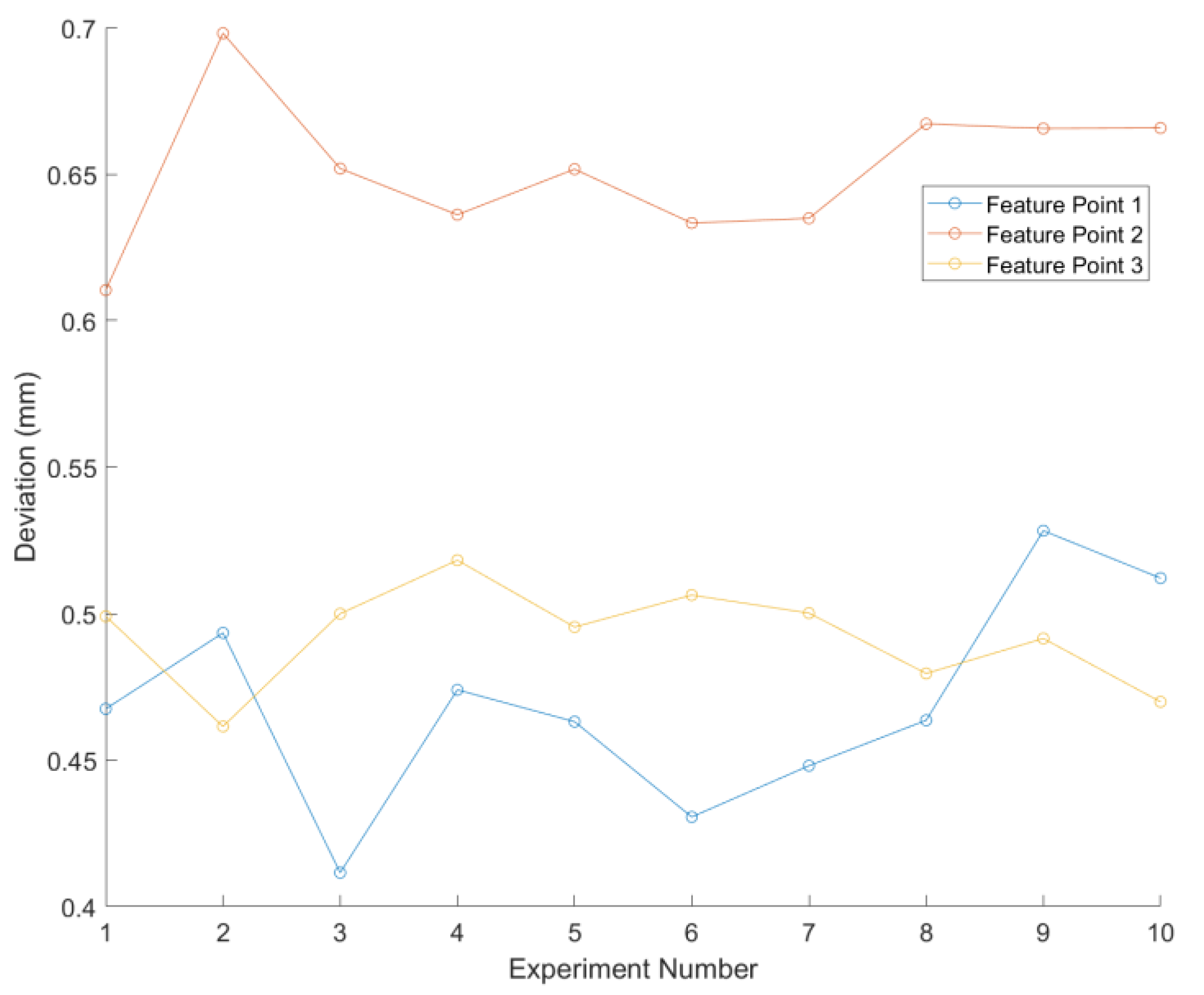
| Feature Points | Feature Point 1 | Feature Point 2 | Feature Point 3 |
|---|---|---|---|
| Average Deviation (mm) | 0.4567 | 0.6374 | 0.4856 |
| Length | Point Cloud (mm) | Deviation (mm) | Angle Parameters | Point Cloud Data (°) |
|---|---|---|---|---|
| 50.3947 | 0.3947 | 53.4567 | ||
| 50.4891 | 0.5109 | 53.0064 | ||
| 50.6713 | 0.6713 | 53.3356 | ||
| 50.4513 | 0.4513 | 52.9278 | ||
| Average | 50.2516 | 0.5071 | Average | 53.1816 |
Disclaimer/Publisher’s Note: The statements, opinions and data contained in all publications are solely those of the individual author(s) and contributor(s) and not of MDPI and/or the editor(s). MDPI and/or the editor(s) disclaim responsibility for any injury to people or property resulting from any ideas, methods, instructions or products referred to in the content. |
© 2024 by the authors. Licensee MDPI, Basel, Switzerland. This article is an open access article distributed under the terms and conditions of the Creative Commons Attribution (CC BY) license (https://creativecommons.org/licenses/by/4.0/).
Share and Cite
Lin, J.; Feng, Y.; Ren, W.; Feng, J.; Zheng, J. Position-Constrained Calibration Compensation for Hand–Eye Calibration in Industrial Robots. Sensors 2024, 24, 7554. https://doi.org/10.3390/s24237554
Lin J, Feng Y, Ren W, Feng J, Zheng J. Position-Constrained Calibration Compensation for Hand–Eye Calibration in Industrial Robots. Sensors. 2024; 24(23):7554. https://doi.org/10.3390/s24237554
Chicago/Turabian StyleLin, Jinsong, Yuxing Feng, Wenze Ren, Jiahui Feng, and Jun Zheng. 2024. "Position-Constrained Calibration Compensation for Hand–Eye Calibration in Industrial Robots" Sensors 24, no. 23: 7554. https://doi.org/10.3390/s24237554
APA StyleLin, J., Feng, Y., Ren, W., Feng, J., & Zheng, J. (2024). Position-Constrained Calibration Compensation for Hand–Eye Calibration in Industrial Robots. Sensors, 24(23), 7554. https://doi.org/10.3390/s24237554