
Research on Real-Time Roundup and Dynamic Allocation Methods for Multi-Dynamic Target Unmanned Aerial Vehicles


Abstract
1. Introduction
- (1)
- A real-time dynamic obstacle avoidance model is designed based on an artificial potential field function, in which all mission UAVs are able to avoid obstacles relatively smoothly under continuously applied perturbations. Moreover, there is also a potential field constraint between UAVs in producing a certain roundup formation.
- (2)
- A multi-dynamic target allocation scheme is designed to converge the environmental information perceived by multiple targets to form a collaborative strategy for the group and a control scheme for the individual based on further consideration of the group UAV constraints. The optimal allocation strategy is derived by establishing an evaluation index function, linearly matching from the perspective of the target UAVs, and combining the total cost of all the mission UAVs.
- (3)
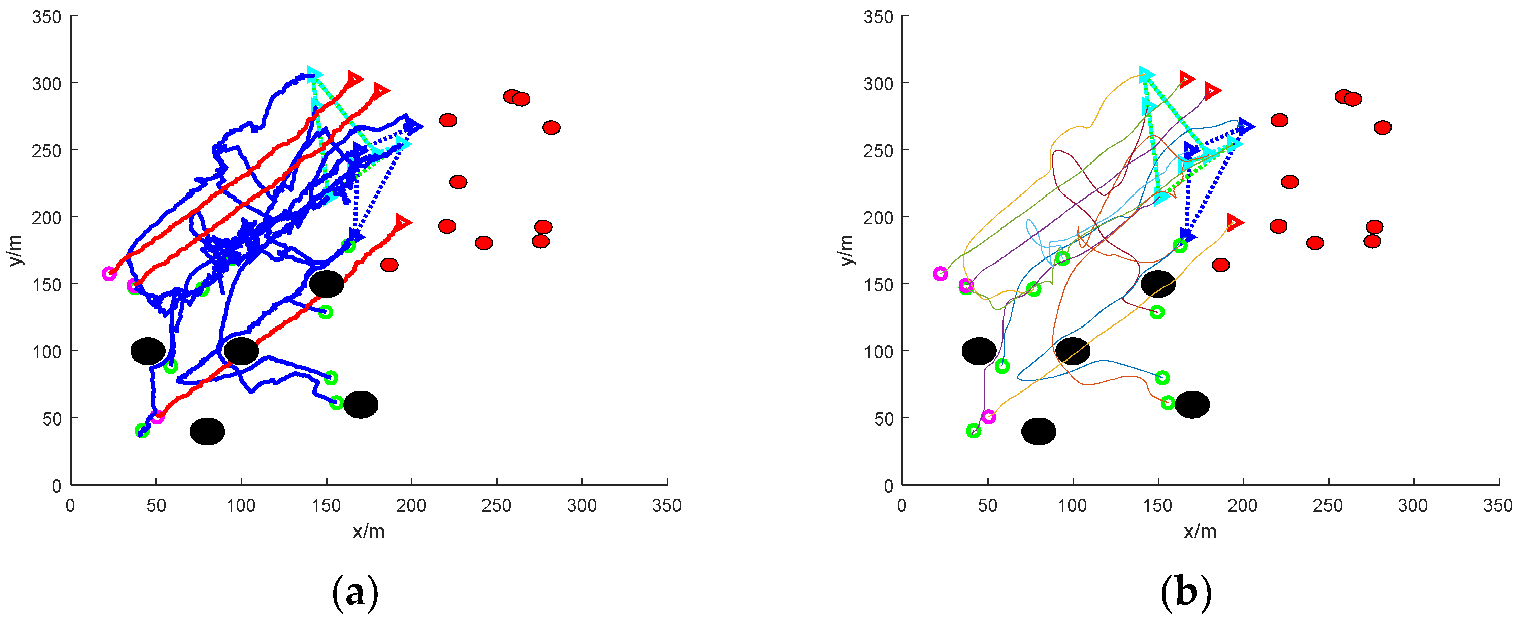
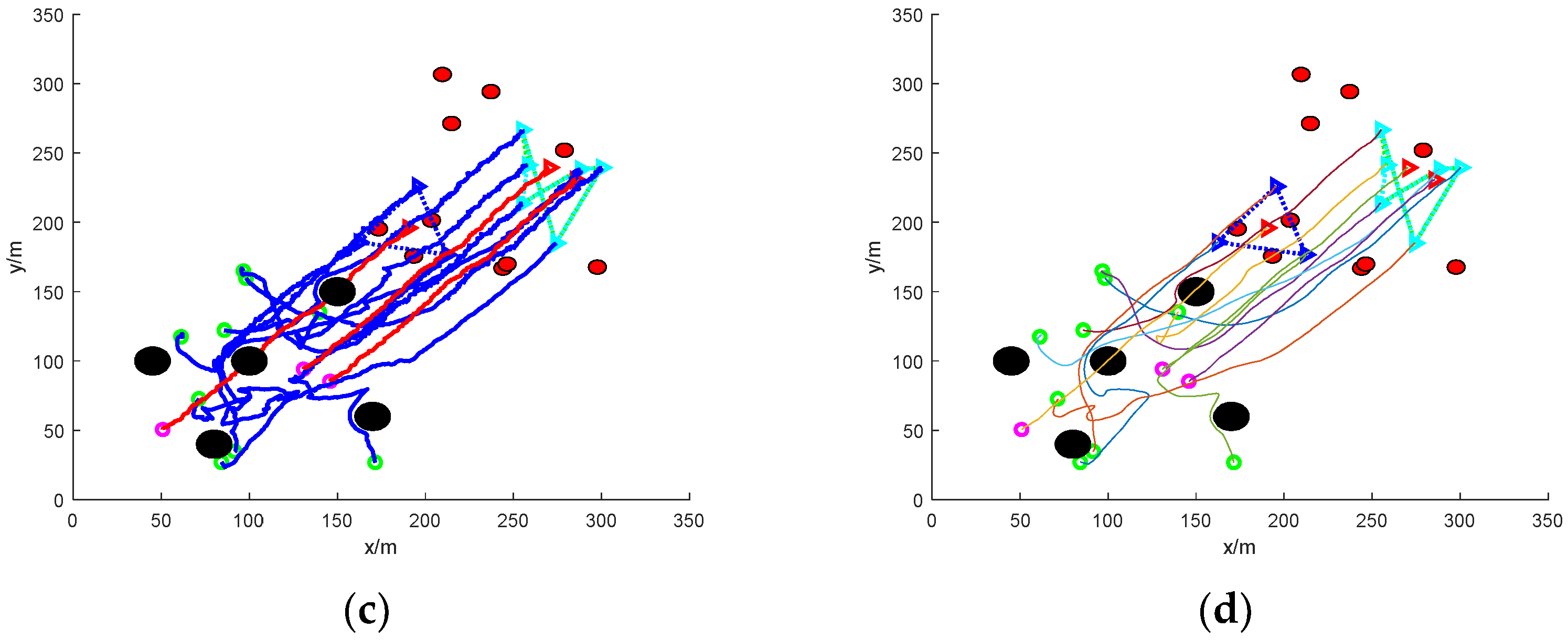
- The path of the roundup process is smoothed and optimized. The planned paths of all the UAVs are jittery due to the setup of continuous interference. The paths of all the UAVs are smoothed by means of Bessel curves to obtain smooth and stable feasible roundup flight paths.
2. Preliminaries
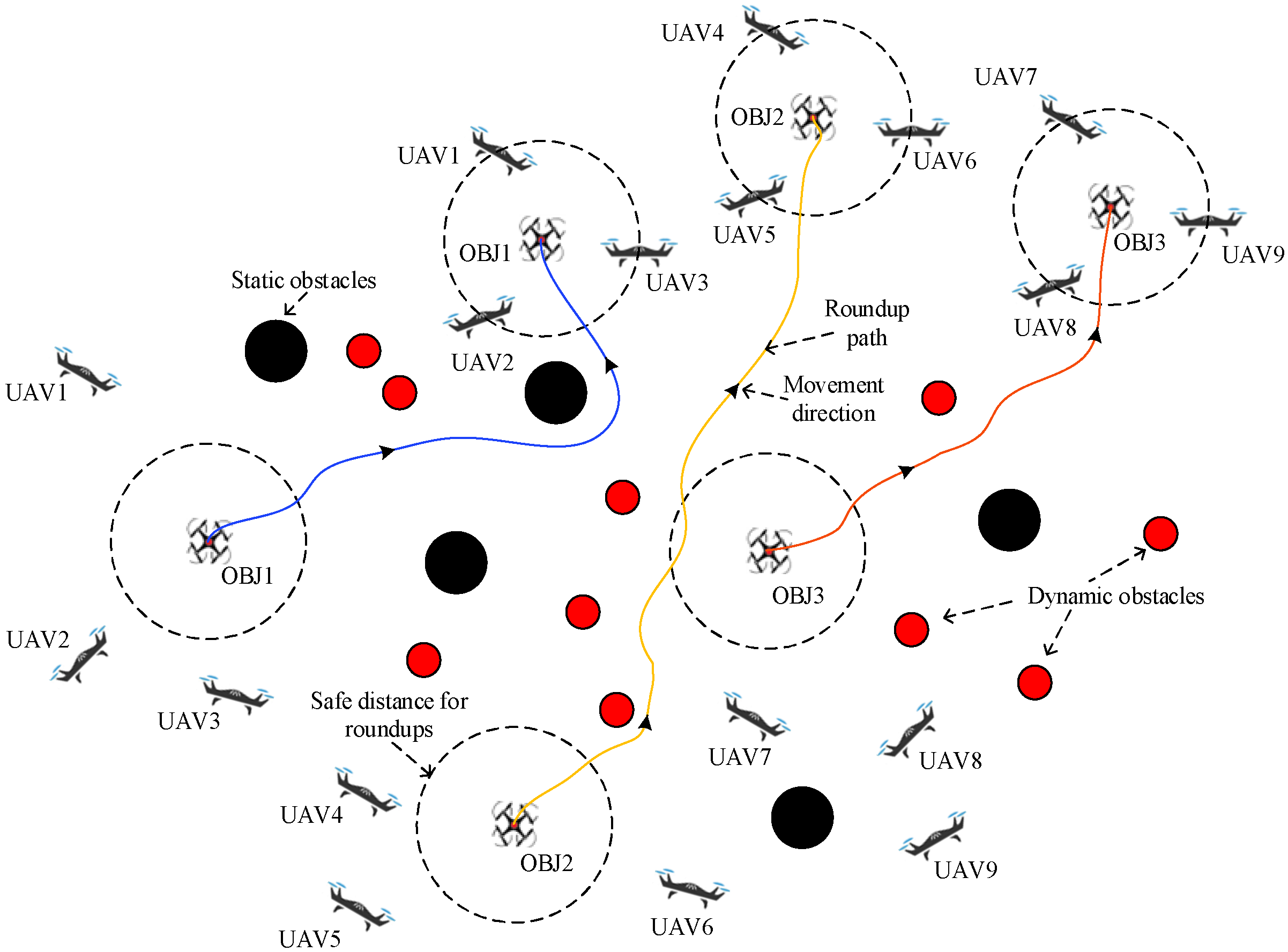
2.1. Problem Model
2.2. Artificial Potential Field
3. Design of Algorithm
3.1. Real-Time Dynamic Obstacle Avoidance Based on Boundary Thresholding
3.2. Identify Target Escape Modes
3.3. Assignment Roundup Distribution Strategy
4. Simulation and Analysis of Results
4.1. Simulation Settings
4.2. Result Analysis
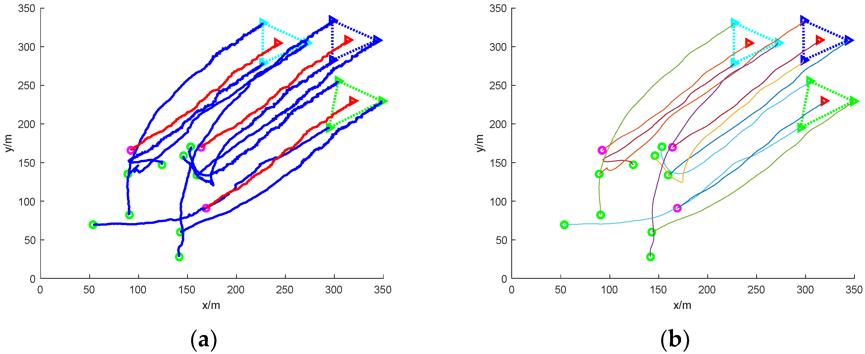
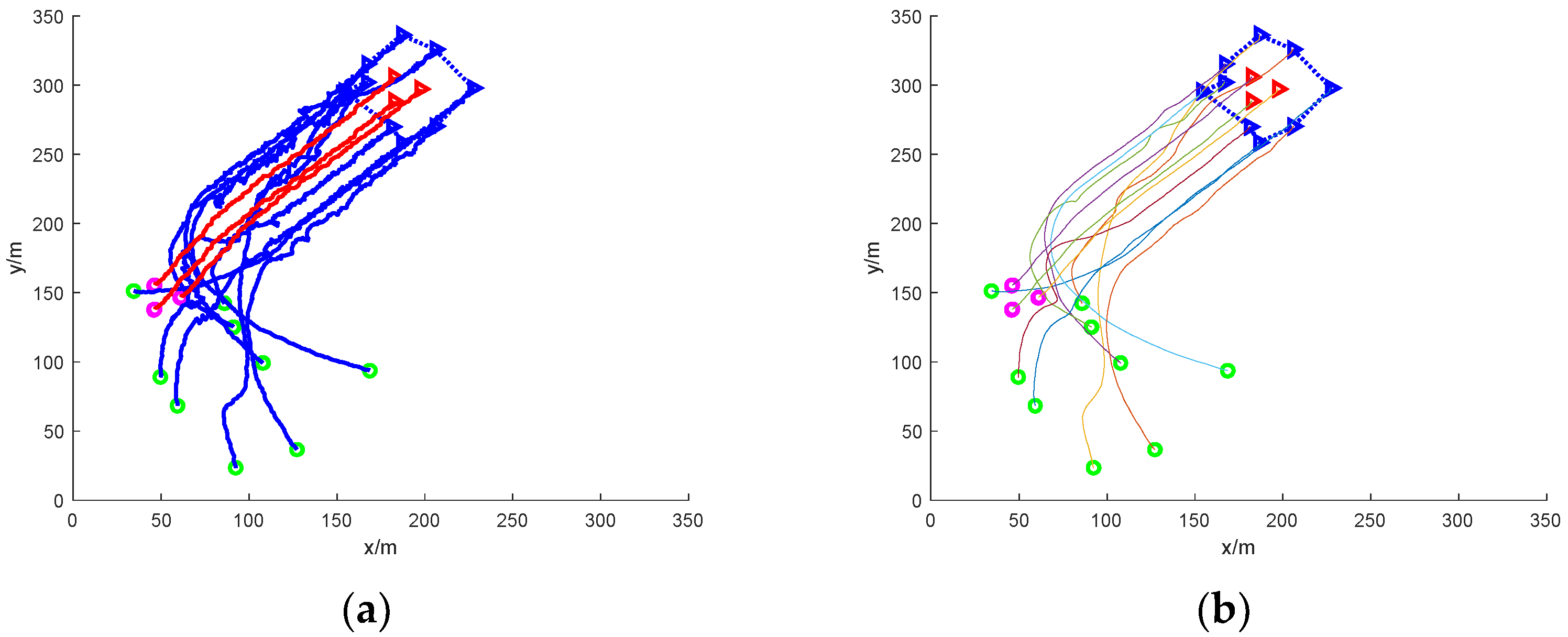
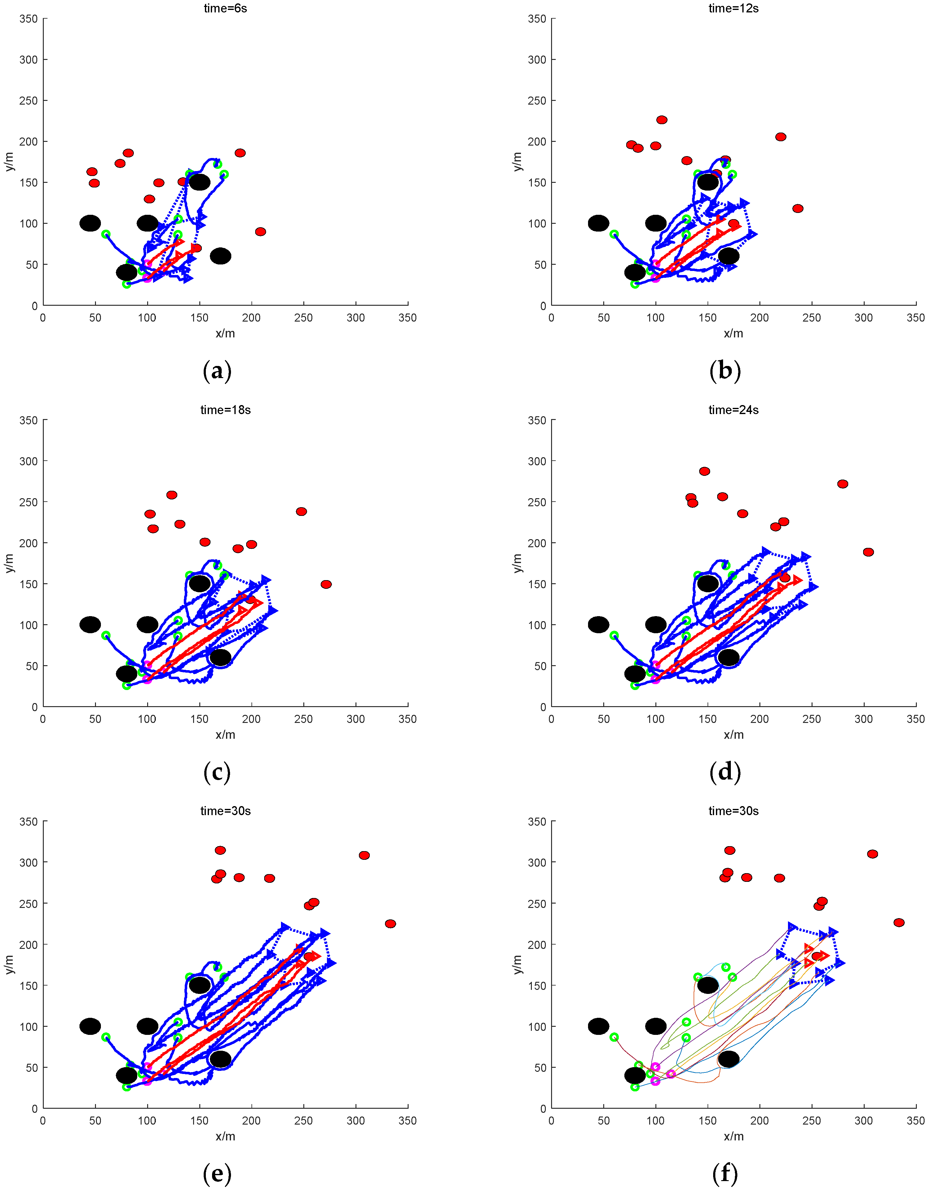
- (1)
- Scattered escape: nine mission UAVs rounding up three dynamic targets
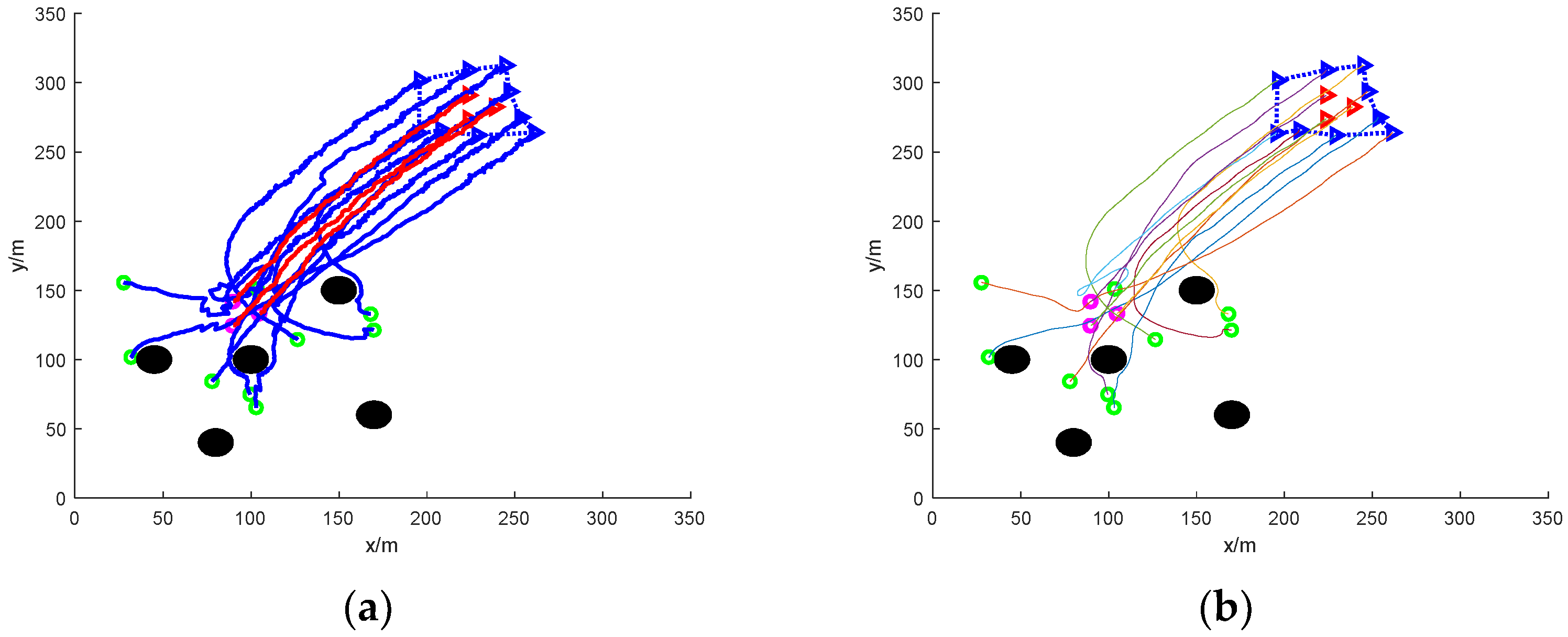
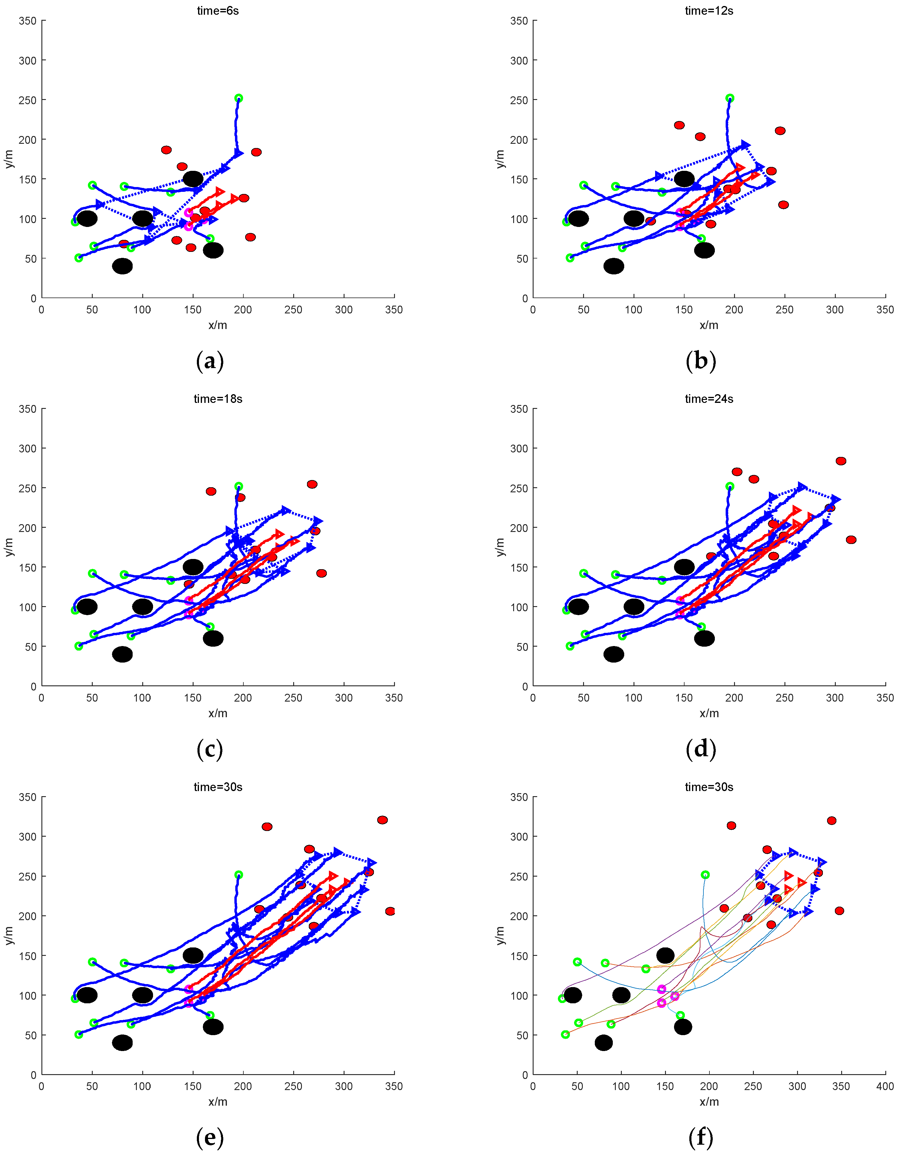
- (2)
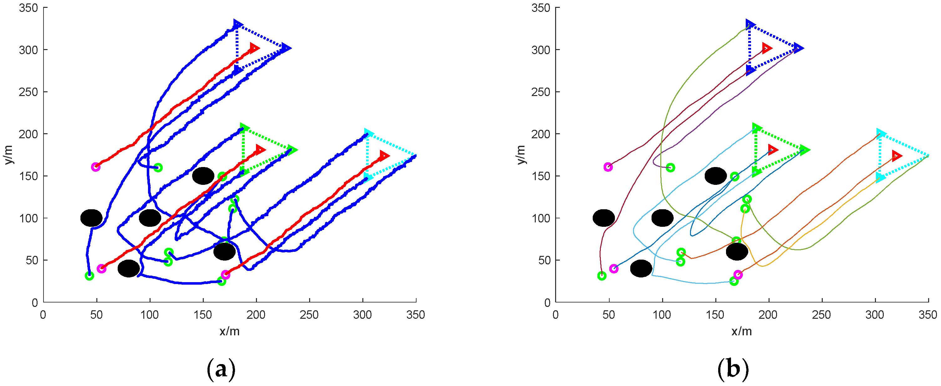
- Formation escape: nine UAVs working together to round up three formation targets
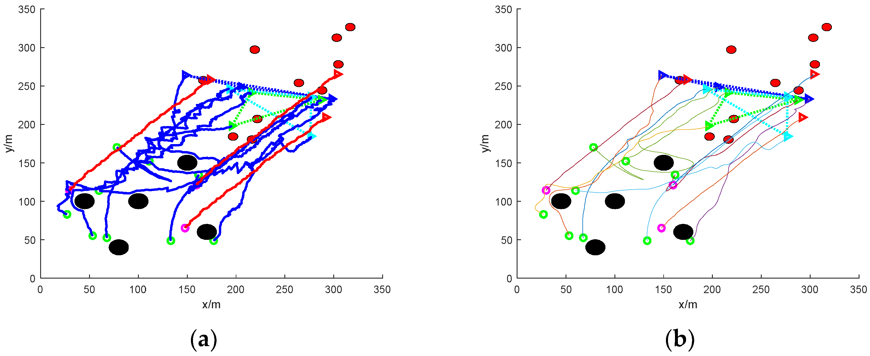
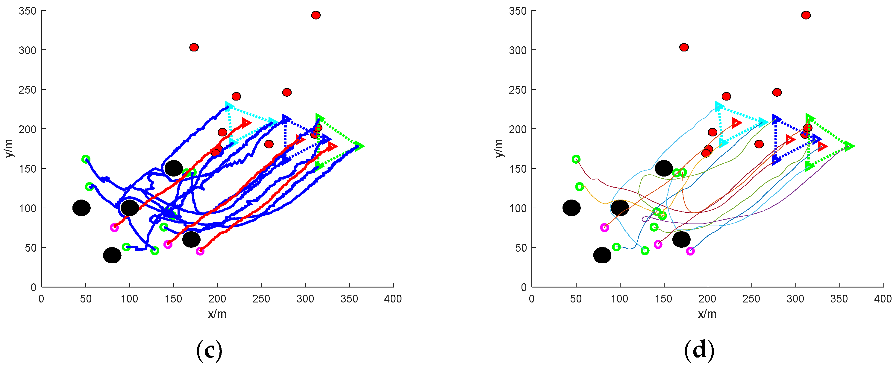
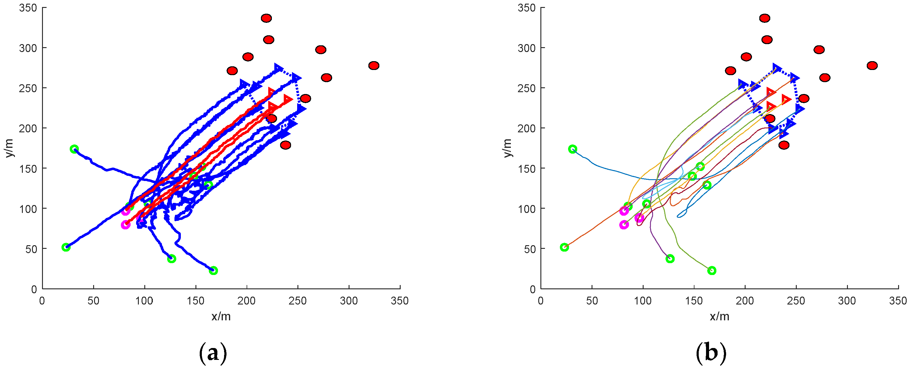
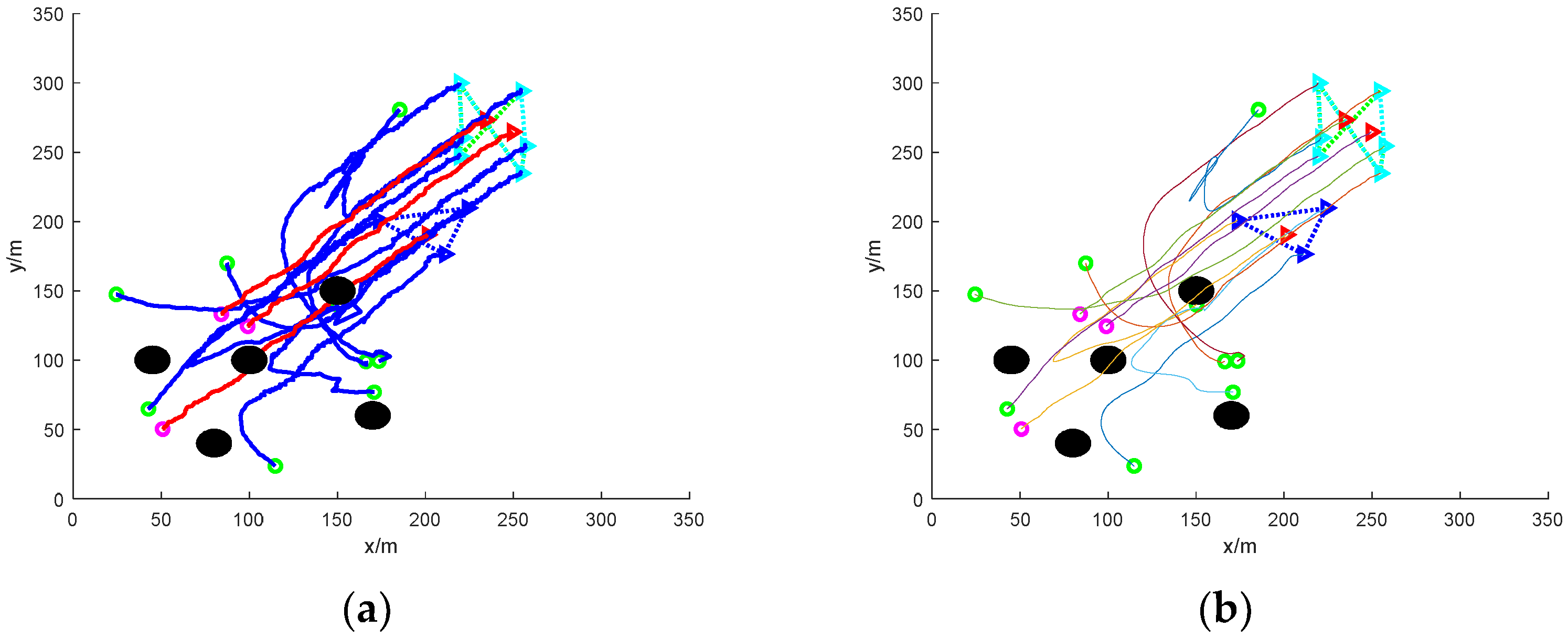
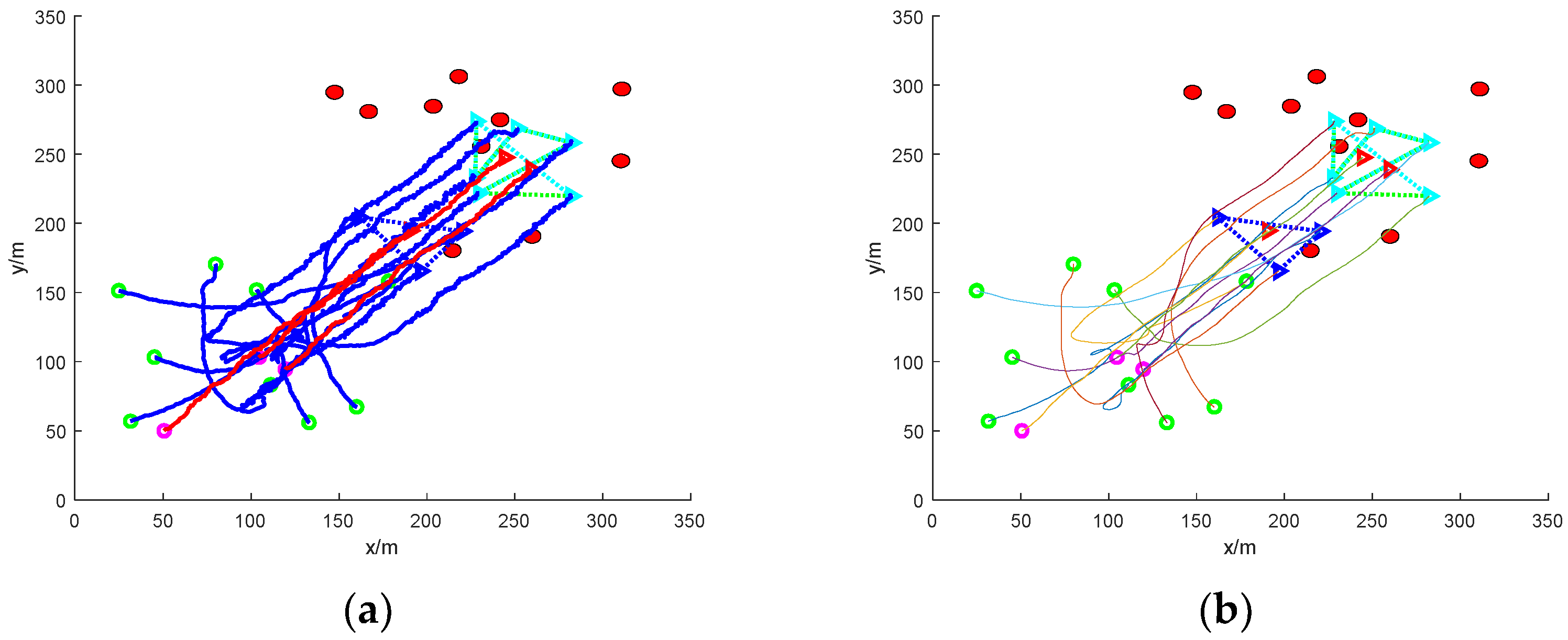
- (3)
- Escape in groups: nine mission UAVs are split into two groups and work together to round up three escaped targets
5. Conclusions
Author Contributions
Funding
Institutional Review Board Statement
Informed Consent Statement
Data Availability Statement
Acknowledgments
Conflicts of Interest
References
- Yakıcı, E.; Karatas, M.; Eriskin, L.; Cicek, E. Location and routing of armed Unmanned Aerial Vehicles and carrier platforms against mobile targets. Comput. Oper. Res. 2024, 169, 106727. [Google Scholar] [CrossRef]
- Gong, X.; Chen, W.; Lei, W.; Wang, J.; Chen, Z.; Li, Y. Analytical game strategies for active UAV defense considering response delays. Def. Technol. 2024, in press. [CrossRef]
- Aljohani, M.; Mukkamala, R.; Olariu, S. Autonomous Strike UAVs in Support of Homeland Security Missions: Challenges and Preliminary Solutions. IEEE Access 2024, 12, 90979–90996. [Google Scholar] [CrossRef]
- Zhong, Y.; Li, H.; Sun, Q.; Huang, Z.; Zhang, Y. A kill chain optimization method for improving the resilience of unmanned combat system-of-systems. Chaos Solitons Fractals 2024, 181, 114685. [Google Scholar] [CrossRef]
- Zhuang, X.; Li, D.; Wang, Y.; Liu, X.; Li, H. Optimization of high-speed fixed-wing UAV penetration strategy based on deep reinforcement learning. Aerosp. Sci. Technol. 2024, 148, 109089. [Google Scholar] [CrossRef]
- Li, B.; Wang, J.; Song, C.; Yang, Z.; Wan, K.; Zhang, Q. Multi-UAV roundup strategy method based on deep reinforcement learning CEL-MADDPG algorithm. Expert Syst. Appl. 2024, 245, 123018. [Google Scholar] [CrossRef]
- Ding, L.; Tang, Y.; Wang, T.; Xie, T.; Huang, P.; Yang, B. A Cooperative Decision-Making Approach Based on a Soar Cognitive Architecture for Multi-Unmanned Vehicles. Drones 2024, 8, 155. [Google Scholar] [CrossRef]
- Huang, Z.; Kuang, Z.; Lin, S.; Hou, F.; Liu, A. Energy-Efficient Joint Trajectory and Reflecting Design in IRS-Enabled UAV Edge Computing. IEEE Internet Things J. 2024, 11, 21872–21884. [Google Scholar] [CrossRef]
- Al-Lqubaydhi, N.; Alenezi, A.; Alanazi, T.; Senyor, A.; Alanezi, N.; Alotaibi, B.; Alotaibi, M.; Razaque, A.; Hariri, S. Deep learning for unmanned aerial vehicles detection: A review. Comput. Sci. Rev. 2024, 51, 100614. [Google Scholar] [CrossRef]
- Wang, H.; Wang, J. Enhancing multi-UAV air combat decision making via hierarchical reinforcement learning. Sci. Rep. 2024, 14, 4458. [Google Scholar] [CrossRef]
- Su, W.; Gao, M.; Gao, X.; Fang, D.; Xuan, Z. An Online Attack Decision Method for Unmanned Aerial Vehicle Cluster in Uncertain Environments. IEEE Sens. J. 2024, 24, 18457–18466. [Google Scholar] [CrossRef]
- Zhou, Y.; Kong, X.; Lin, K.-P.; Liu, L. Novel task decomposed multi-agent twin delayed deep deterministic policy gradient algorithm for multi-UAV autonomous path planning. Knowl.-Based Syst. 2024, 287, 111462. [Google Scholar] [CrossRef]
- Ni, J.; Tang, G.; Mo, Z.; Cao, W.; Yang, S.X. An improved potential game theory based method for multi-UAV cooperative search. IEEE Access 2020, 8, 47787–47796. [Google Scholar] [CrossRef]
- Luo, D.; Fan, Z.; Yang, Z.; Xu, Y. Multi-UAV cooperative maneuver decision-making for pursuit-evasion using improved MADRL. Def. Technol. 2024, 35, 187–197. [Google Scholar] [CrossRef]
- Huang, H.; Jiang, Z.; Yan, T.; Bai, Y. Dynamic Task Allocation for Heterogeneous Multi-UAVs in Uncertain Environments Based on 4DI-GWO Algorithm. Drones 2024, 8, 236. [Google Scholar] [CrossRef]
- Bai, Z.; Zhou, H.; Shi, J.; Xing, L.; Wang, J. A hybrid multi-objective evolutionary algorithm with high solving efficiency for UAV defense programming. Swarm Evol. Comput. 2024, 87, 101572. [Google Scholar] [CrossRef]
- Wang, G.; Wang, F.; Wang, J.; Li, M.; Gai, L.; Xu, D. Collaborative target assignment problem for large-scale UAV swarm based on two-stage greedy auction algorithm. Aerosp. Sci. Technol. 2024, 149, 109146. [Google Scholar] [CrossRef]
- Cui, Y.; Xu, J.; Xing, W.; Huang, F.; Yan, Z.; Du, X. Anti-disturbance cooperative formation containment control for multiple autonomous underwater vehicles with collision-free and actuator saturation constraints. J. Frankl. Inst. 2024, 361, 107063. [Google Scholar] [CrossRef]
- Du, Z.; Zhang, H.; Wang, Z.; Yan, H. Model Predictive Formation Tracking-Containment Control for Multi-UAVs with Obstacle Avoidance. IEEE Trans. Syst. Man. Cybern. Syst. 2024, 54, 3404–3414. [Google Scholar] [CrossRef]
- Song, G.; Xu, J.; Deng, L.; Zhao, N. Robust distributed fixed-time cooperative hunting control for multi-quadrotor with obstacles avoidance. ISA Trans. 2024, 151, 73–85. [Google Scholar] [CrossRef]
- Wang, Z.; Gong, H.; Nie, M.; Liu, X. Research on Multi-UAV Cooperative Dynamic Path Planning Algorithm Based on Conflict Search. Drones 2024, 8, 274. [Google Scholar] [CrossRef]
- Xing, X.; Zhou, Z.; Li, Y.; Xiao, B.; Xun, Y. M Multi-UAV Adaptive Cooperative Formation Trajectory Planning Based on An Improved MATD3 Algorithm of Deep Reinforcement Learning. IEEE Trans. Veh. Technol. 2024, 73, 12484–12499. [Google Scholar] [CrossRef]


| Mission UAV | Target UAV | Static Obstacles | Dynamic Obstacles | |
|---|---|---|---|---|
| Number (pcs) | 9 | 3 | 5 | 10 |
| Radius (m) | 1 | 1 | 10 | 5 |
| Speed (m/s) | 5~20 | 5~10 | 0 | −10~20 |
| No. | Component Name | Parameter Setting | Parameter Data |
|---|---|---|---|
| 1 | Main control unit | Preset flight modes, automatic stabilization control | Processor: STM32F427, frequency: 168 MHz |
| 2 | GPS module | High-precision positioning mode | Positioning accuracy: 2 m, update rate: 10 Hz |
| 3 | IMU sensor | Integrated accelerometer and gyroscope | Accelerometer range: ±40 g, gyroscope range: ±2000°/s |
| 4 | Communication module | Frequency setting, power adjustment | Frequency range: 902–928 MHz, transmission distance: 9 km |
| 5 | Drive module push | Thrust and RPM settings | Thrust: 2200 g, speed: 2400 rpm |
| 6 | Drive module | Thrust and speed settings | Thrust: 2200 g, speed: 2400 rpm |
| 7 | Power module | Voltage monitoring, discharge rate | Capacity: 5000 mAh, discharge rate: 20 C |
| 8 | Camera module | Resolution and frame rate settings | Resolution: 1280 × 960, frame rate: 60 fps |
| Parameter Setting | Parameter Data | Parameter Setting | Parameter Data |
|---|---|---|---|
| Constant coefficient () | 3 | Obstacle point repulsion coefficient () | 100 |
| Exponential constant coefficient () | 2 | Maximum distance of obstacle point repulsion () | 14 m |
| Boundary value of repulsion region () | 10 m | Boundary value of target UAV escape state () | 10 m |
| Equilibrium region boundary value () | 30 m | Weight value constant () | 1 |
| Equilibrium region boundary value () | 100 m | Weight value constant () | 1 |
| Constant coefficient () | 2 | Weight value constant () | 1 |
| Interference coefficient of the angle of motion | 0.1 |
Disclaimer/Publisher’s Note: The statements, opinions and data contained in all publications are solely those of the individual author(s) and contributor(s) and not of MDPI and/or the editor(s). MDPI and/or the editor(s) disclaim responsibility for any injury to people or property resulting from any ideas, methods, instructions or products referred to in the content. |
© 2024 by the authors. Licensee MDPI, Basel, Switzerland. This article is an open access article distributed under the terms and conditions of the Creative Commons Attribution (CC BY) license (https://creativecommons.org/licenses/by/4.0/).
Share and Cite
Li, J.; Wei, R.; Zhang, Q.; Shi, R.; Jiang, B. Research on Real-Time Roundup and Dynamic Allocation Methods for Multi-Dynamic Target Unmanned Aerial Vehicles. Sensors 2024, 24, 6565. https://doi.org/10.3390/s24206565
Li J, Wei R, Zhang Q, Shi R, Jiang B. Research on Real-Time Roundup and Dynamic Allocation Methods for Multi-Dynamic Target Unmanned Aerial Vehicles. Sensors. 2024; 24(20):6565. https://doi.org/10.3390/s24206565
Chicago/Turabian StyleLi, Jinpeng, Ruixuan Wei, Qirui Zhang, Ruqiang Shi, and Benqi Jiang. 2024. "Research on Real-Time Roundup and Dynamic Allocation Methods for Multi-Dynamic Target Unmanned Aerial Vehicles" Sensors 24, no. 20: 6565. https://doi.org/10.3390/s24206565
APA StyleLi, J., Wei, R., Zhang, Q., Shi, R., & Jiang, B. (2024). Research on Real-Time Roundup and Dynamic Allocation Methods for Multi-Dynamic Target Unmanned Aerial Vehicles. Sensors, 24(20), 6565. https://doi.org/10.3390/s24206565