

Coordinated Decision Control of Lane-Change and Car-Following for Intelligent Vehicle Based on Time Series Prediction and Deep Reinforcement Learning

Abstract
1. Introduction
- (1)
- A hierarchical lane-change and car-following coordinated decision-making control model aimed at improving driving efficiency is established, which divides the lane-change trajectory planning problem into longitudinal velocity planning and lateral trajectory planning, and the trajectory is planned based on the driving condition identification.
- (2)
- Multi-step time series prediction information is introduced to realize the prediction of the future driving state of the surrounding vehicles, which provides the basis for lane-change decision-making and trajectory planning.
- (3)
- A three-layer safety guarantee mechanism of a decision-making layer, planning layer and control layer is constructed to ensure the safety of the whole lane-change and car-following process.
- (4)
- The lane-change data in the NGSIM dataset are extracted to construct the training scenario, and the lane-change scenarios dataset is established to improve the authenticity and complexity of the training environment, and to verify the effectiveness of the model.
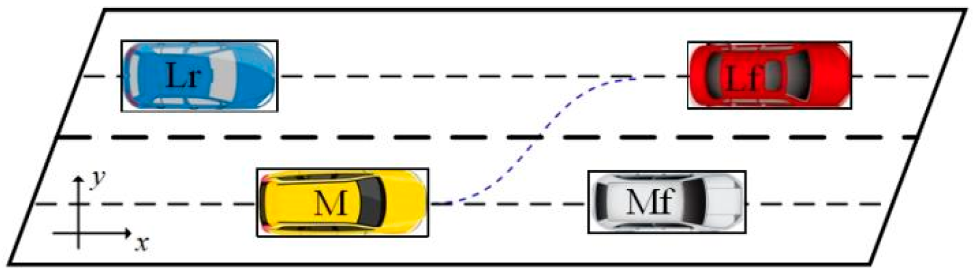
2. Analysis of Lane-Change Behavior
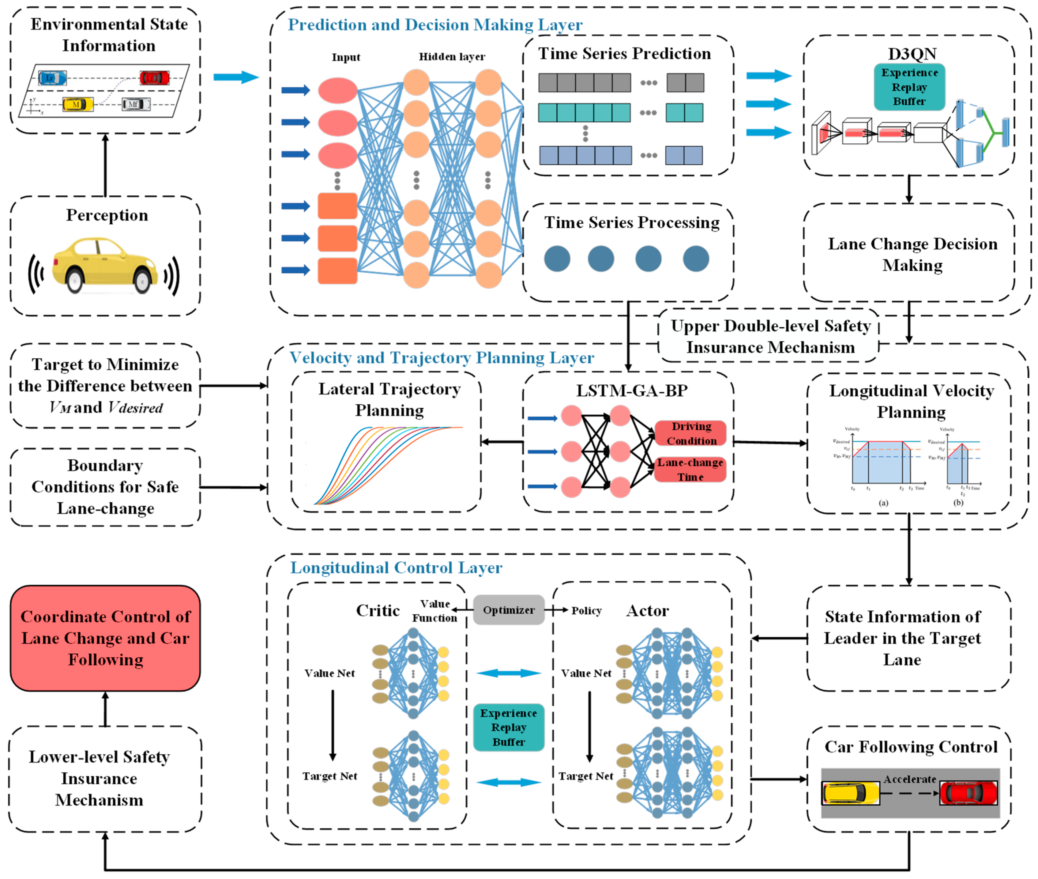
3. Overview of the Framework
4. Lane-Change Decision-Making Model
4.1. Time Series Prediction Module
4.2. Lane-Change Decision-Making Based on Time Series Prediction and Deep Reinforcement Learning
5. Lateral and Longitudinal Trajectory Planning Based on Driving Condition Recognition
5.1. Lateral Trajectory Planning and Driving Condition Recognition
5.2. Longitudinal Velocity Planning Considering the Car-Follow Characterization
6. DDPG-Based Lower Level Control Model
7. Simulation Verification
7.1. Lane-Change Decision-Making Model Training Results
7.2. Validation of Lateral Trajectory Planning
7.3. Car-Following Model Validation
7.4. Overall Model Validation
8. Conclusions
Author Contributions
Funding
Institutional Review Board Statement
Informed Consent Statement
Data Availability Statement
Conflicts of Interest
References
- Zhu, X.L.; Wang, H.C.; You, H.M.; Zhang, W.H.; Zhang, Y.Y.; Liu, S.; Chen, J.J.; Wang, Z.; Li, K.Q. Survey on Testing of Intelligent Systems in Autonomous Vehicles. J. Softw. 2021, 32, 2056–2077. [Google Scholar]
- Mehmood, A.; Liaquat, M.; Bhatti, A.I.; Rasool, E. Trajectory Planning and Control for Lane-Change of Autonomous Vehicle. In Proceedings of the 2019 5th International Conference on Control, Automation and Robotics (ICCAR), Beijing, China, 19–22 April 2019; pp. 331–335. [Google Scholar]
- Qiao, B.; Wu, X. Real Time Trajectory Re-planning for Autonomous Vehicle Lane Changing in Uncertain Traffic. In Proceedings of the 2019 IEEE 28th International Symposium on Industrial Electronics (ISIE), Vancouver, BC, Canada, 12–14 June 2019; pp. 1524–1529. [Google Scholar]
- An, L.; Chen, T.; Cheng, A.; Fang, W. A simulation on the path planning of intelligent vehicles based on artificial potential field algorithm. Automot. Eng. 2017, 39, 1451–1456. [Google Scholar]
- Qu, D.; Zhang, K.; Song, H.; Jia, Y.; Dai, S. Analysis and Modeling of Lane-Changing Game Strategy for Autonomous Driving Vehicles. IEEE Access 2022, 10, 69531–69542. [Google Scholar] [CrossRef]
- Kesting, A.; Treiber, M.; Helbing, D. Generallane-changing model MOBIL for car-following models. Transp. Res. Rec. 2007, 1999, 86. [Google Scholar] [CrossRef]
- Jin, C.J.; Knoop, V.L.; Li, D.; Meng, L.Y.; Wang, H. Discretionary lane-changing behavior: Empirical validation for one realistic rule-based model. Transp. A Transp. Sci. 2018, 15, 244–262. [Google Scholar] [CrossRef]
- Yang, Q.I.; Koutsopoulos, H.N. A microscopic traffic simulator for evaluation of dynamic traffic management systems. Transp. Res. C 1996, 4, 113–129. [Google Scholar] [CrossRef]
- Ahmed, K.I. Modeling Drivers’ Acceleration and Lane Changing Behavior. Ph.D. Thesis, Massachusetts Institute of Technology, Cambridge, MA, USA, 1999. [Google Scholar]
- Díaz-Álvarez, A.; Clavijo, M.; Jiménez, F.; Talavera, E.; Serradilla, F. Modelling the human lane-change execution behaviour through Multilayer Perceptrons and Convolutional Neural Networks. Transp. Res. F Traffic Psychol. Behav. 2018, 56, 134–148. [Google Scholar] [CrossRef]
- Hou, Y.; Edara, P.; Sun, C. Modeling Mandatory Lane Changing Using Bayes Classifier and Decision Trees. IEEE Trans. Intell. Transp. Syst. 2014, 15, 647–655. [Google Scholar] [CrossRef]
- Cui, J.-M.; Yu, G.-Z.; Zhou, B.; Li, C.-J.; Ma, J.W.; Xu, G.-Y. Mandatory lane change decision-making model based on neural network. J. Beijing Univ. Aeronaut. Astronaut. 2022, 48, 890–897. [Google Scholar]
- Xie, D.F.; Fang, Z.Z.; Jia, B.; He, Z. A data-driven lane-changing model based on deep learning. Transp. Res. C Emerg. Technol. 2019, 106, 41–60. [Google Scholar] [CrossRef]
- Liu, M.; Wan, Y.; Lewis, F.L.; Nageshrao, S.; Filev, D. A Three-Level Game-Theoretic Decision-Making Framework for Autonomous Vehicles. IEEE Trans. Intell. Transp. Syst. 2022, 23, 20298–20308. [Google Scholar] [CrossRef]
- Feng, Z.; Song, W.; Fu, M.; Yang, Y.; Wang, M. Decision-Making and Path Planning for Highway Autonomous Driving Based on Spatio-Temporal Lane-Change Gaps. IEEE Syst. J. 2021, 16, 3249–3259. [Google Scholar] [CrossRef]
- Gipps, P.G. A model for the structure of lane-changing decision. Transp. Res. B Methodol. 1986, 20, 403–414. [Google Scholar] [CrossRef]
- Toledo, T.; Koutsopoulos, H.N.; Ben-Akiva, M.E. Modeling integrated lane-changing behavior. Transp. Res. Rec. J. Transp. Res. Board 2003, 1857, 30–38. [Google Scholar] [CrossRef]
- Hidas, P. Modelling vehicle interactions merging and weaving. Transp. Technol. 2005, 13, 37–62. [Google Scholar]
- Wang, J. A simulation model for motozwvay merging behaviour. Transp. Traffic Theory 2005, 16, 281–301. [Google Scholar]
- Motamedidehkordi, N.; Amini, S.; Hoffmann, S.; Busch, F.; Fitriyanti, M.R. Modeling tactical lane-change behavior for automated vehicles: A supervised machine learning approach. In Proceedings of the 2017 IEEE International Conference on Models and Technologies for Intelligent Transportation Systems (MT-ITS), Naples, Italy, 26–28 June 2017; pp. 268–273. [Google Scholar]
- Xu, B.; Liu, X.; Wang, Z.-Y.; Liu, F.-H.; Liang, J. Fusion decision model for vehicle lane change with gradient boosting decision tree. J. Zhejiang Univ. Eng. Sci. 2019, 53, 1171–1181. [Google Scholar]
- Gu, X.; Han, Y.; Yu, J. Vehicle lane-changing decision model based on decision mechanism and support vector machine. J. Harbin Inst. Technol. 2020, 52, 111–121. [Google Scholar]
- Li, G.; Yang, Y.; Li, S.; Qu, X.; Lyu, N.; Li, S.E. Precise Decision-Making Learning for Automated Vehicles in Lane-Change Scenario Based on Parameter Description. J. Tongji Univ. Nat. Sci. 2021, 49, 132–140. [Google Scholar]
- Niu, G.; Li, W.; Wei, H. Intelligent Vehicle Lane Changing Trajectory Planning Based on Double Quintic Polynomials. Automot. Eng. 2021, 43, 978–986, 1004. [Google Scholar]
- Li, Z.; Liang, H.; Zhao, P.; Wang, S.; Zhu, H. Efficent Lane Change Path Planning based on Quintic spline for Autonomous Vehicles. In Proceedings of the 2020 IEEE International Conference on Mechatronics and Automation (ICMA), Beijing, China, 13–16 October 2020; pp. 338–344. [Google Scholar]
- Tang, B.; Xu, Z.; Jiang, H.; Cai, Y.; Hu, Z.; Yang, Z. Trajectory Planning of Intelligent Vehicles in Lane Change for Collision Avoidance Based on Segmented Optimization. Automot. Eng. 2022, 44, 831–841. [Google Scholar]
- Xiaorui, W.; Hongxu, Y. A Lane Change Model with the Consideration of Car Following Behavior. Procedia—Soc. Behav. Sci. 2013, 96, 2354–2361. [Google Scholar] [CrossRef]
- Zhang, Y.; Lin, Q.; Wang, J.; Verwer, S.; Dolan, J.M. Lane-Change Intention Estimation for Car-Following Control in Autonomous Driving. IEEE Trans. Intell. Veh. 2018, 3, 276–286. [Google Scholar] [CrossRef]
- Wang, C.; Coifman, B. The Effect of Lane-Change Maneuvers on a Simplified Car-Following Theory. IEEE Trans. Intell. Transp. Syst. 2008, 9, 523–535. [Google Scholar] [CrossRef]
- Dang, R.; Wang, J.; Li, S.E.; Li, K. Coordinated adaptive cruise control system with lane-change assistance. IEEE Trans. Intell. Transp. Syst. 2016, 59, 1176–1185. [Google Scholar] [CrossRef]
- Zhou, Y.; Wang, R.; Ding, R. Multi-objective coordinated control for vehicle during adaptive cruise and lane change process. Huazhong Univ. Sci. Technol. Nat. Sci. Ed. 2022, 50, 108–115. [Google Scholar]
- Hu, Y.; Zhang, L.; Liu, X.; Lei, F. Research on adaptive cruise control strategy with lane changing function. J. Chongqing Univ. Technol. Nat. Sci. 2022, 36, 12–22. [Google Scholar]
- Xu, J.; Du, W.; Sun, H. Safety distance about car-following. J. Traffic Transp. Eng. 2002, 2, 101–104. [Google Scholar]
- Xue-wu, J.; Cong, F.; Xiang-kun, H.; Yu-long, L.; Ya-hui, L. Intention Recognition and Trajectory Prediction for Vehicles Using LSTM Network. China J. Highw. Transp. 2019, 32, 34–42. [Google Scholar]
- Pang, M.-Y. Trajectory Data Based Clustering and Feature Analysis of Vehicle Lane-Changing Behavior. In Proceedings of the 2019 4th International Conference on Electronic Mechanical Control Technology and Transportation (ICECTT), Guilin, China, 26–28 April 2019; pp. 229–233. [Google Scholar]
- Ossen, S.; Hoogendoorn, S. Validity of trajectory-based calibration approach of carfollowing models in presence of measurement errors. Transp. Res. Rec. J. Transp. Res. Board 2008, 2088, 117–125. [Google Scholar] [CrossRef]
- Li, Z.; Huang, X.; Wang, J.; Mu, T. Lane Change Behavior Research Based on NGSIM Vehicle Trajectory Data. In Proceedings of the 2020 Chinese Control and Decision Conference (CCDC), Hefei, China, 22–24 August 2020; pp. 1865–1870. [Google Scholar]


| Parameter | Symbols | Value Range |
|---|---|---|
| Lane-change time | [3 s, 7 s] | |
| Longitudinal velocity | [8 m/s, 34 m/s] | |
| Longitudinal acceleration | [−3 m/s2, 2 m/s2] | |
| Lateral acceleration | [−2.4 m/s2, 2.4 m/s2] |
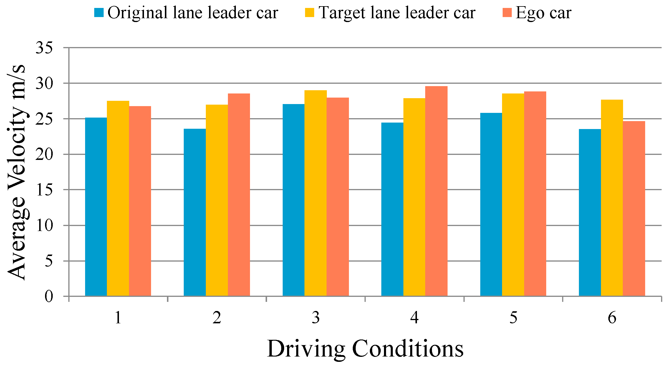
| Conditions | Relationship To The Leader Vehicle In The Initial Lane | Relationship to the leader Vehicle in the Target Lane |
|---|---|---|
| 1 | following | Initial distance > desired distance |
| 2 | Not following | Initial distance > desired distance |
| 3 | ||
| 4 | Not following | Initial distance < desired distance |
| 5 | ||
| 6 | following | Initial distance < desired distance |
| Decision Model | LSTM+D3QN | D3QN | LSTM+DDQN | DDQN | LSTM+SVM | SVM |
|---|---|---|---|---|---|---|
| TPR | 89.37% | 88.64% | 87.48% | 84.90% | 81.27% | 80.98% |
| TNR | 95.10% | 93.79% | 92.30% | 91.90% | 87.96% | 83.03% |
| Accuracy | 94.30% | 93.27% | 91.93% | 90.08% | 83.20% | 81.60% |
| Maximum Error | Average Absolute Error | Root Mean Square Error | |
|---|---|---|---|
| GA-BP | 1.68 s | 0.88 | |
| GA-LSTM-BP | 1.24 s | 0.56 |
| Lane Change Model | NGSIM | SVM | SVM | MOBIL | MOBIL | CD | D3QN |
|---|---|---|---|---|---|---|---|
| Car Following Model | NGSIM | ACC | DDPG | ACC | DDPG | ACC | DDPG |
| Collisions | 0 | 12 | 10 | 4 | 0 | 0 | 0 |
| Average Acceleration (m/s2) | 0.17 | 0.35 | 0.37 | 0.44 | 0.51 | 0.23 | 0.54 |
| Average Velocity (m/s) | 9.09 | 9.31 | 9.25 | 10.36 | 10.49 | 9.78 | 10.68 |
Disclaimer/Publisher’s Note: The statements, opinions and data contained in all publications are solely those of the individual author(s) and contributor(s) and not of MDPI and/or the editor(s). MDPI and/or the editor(s) disclaim responsibility for any injury to people or property resulting from any ideas, methods, instructions or products referred to in the content. |
© 2024 by the authors. Licensee MDPI, Basel, Switzerland. This article is an open access article distributed under the terms and conditions of the Creative Commons Attribution (CC BY) license (https://creativecommons.org/licenses/by/4.0/).
Share and Cite
Zhang, K.; Pu, T.; Zhang, Q.; Nie, Z. Coordinated Decision Control of Lane-Change and Car-Following for Intelligent Vehicle Based on Time Series Prediction and Deep Reinforcement Learning. Sensors 2024, 24, 403. https://doi.org/10.3390/s24020403
Zhang K, Pu T, Zhang Q, Nie Z. Coordinated Decision Control of Lane-Change and Car-Following for Intelligent Vehicle Based on Time Series Prediction and Deep Reinforcement Learning. Sensors. 2024; 24(2):403. https://doi.org/10.3390/s24020403
Chicago/Turabian StyleZhang, Kun, Tonglin Pu, Qianxi Zhang, and Zhigen Nie. 2024. "Coordinated Decision Control of Lane-Change and Car-Following for Intelligent Vehicle Based on Time Series Prediction and Deep Reinforcement Learning" Sensors 24, no. 2: 403. https://doi.org/10.3390/s24020403
APA StyleZhang, K., Pu, T., Zhang, Q., & Nie, Z. (2024). Coordinated Decision Control of Lane-Change and Car-Following for Intelligent Vehicle Based on Time Series Prediction and Deep Reinforcement Learning. Sensors, 24(2), 403. https://doi.org/10.3390/s24020403