
Microwave Receiving System Based on Cryogenic Sensors for the Optical Big Telescope Alt-Azimuth
 , , , , , , add
Show full author list
, , , , , , add
Show full author list
Abstract
1. Introduction
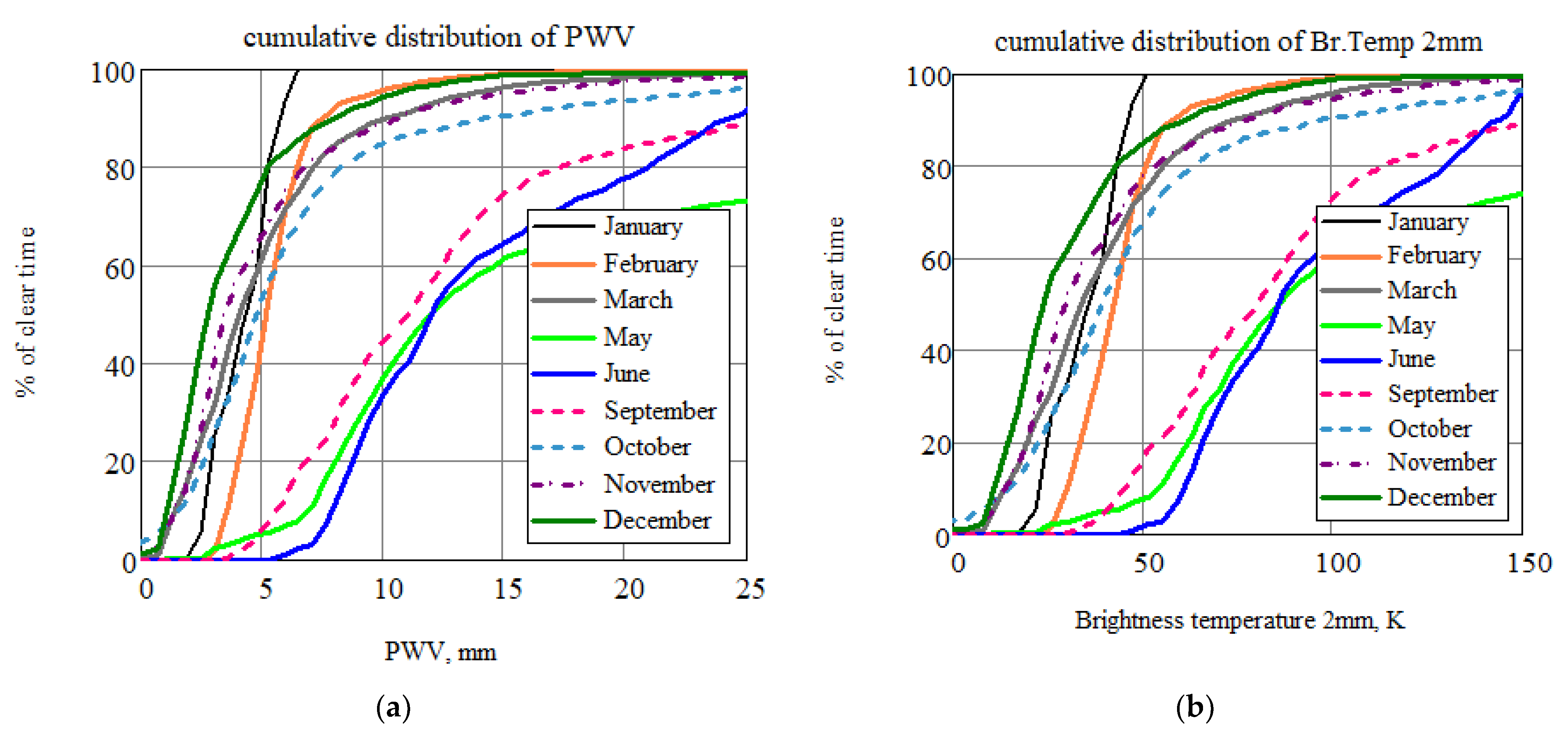
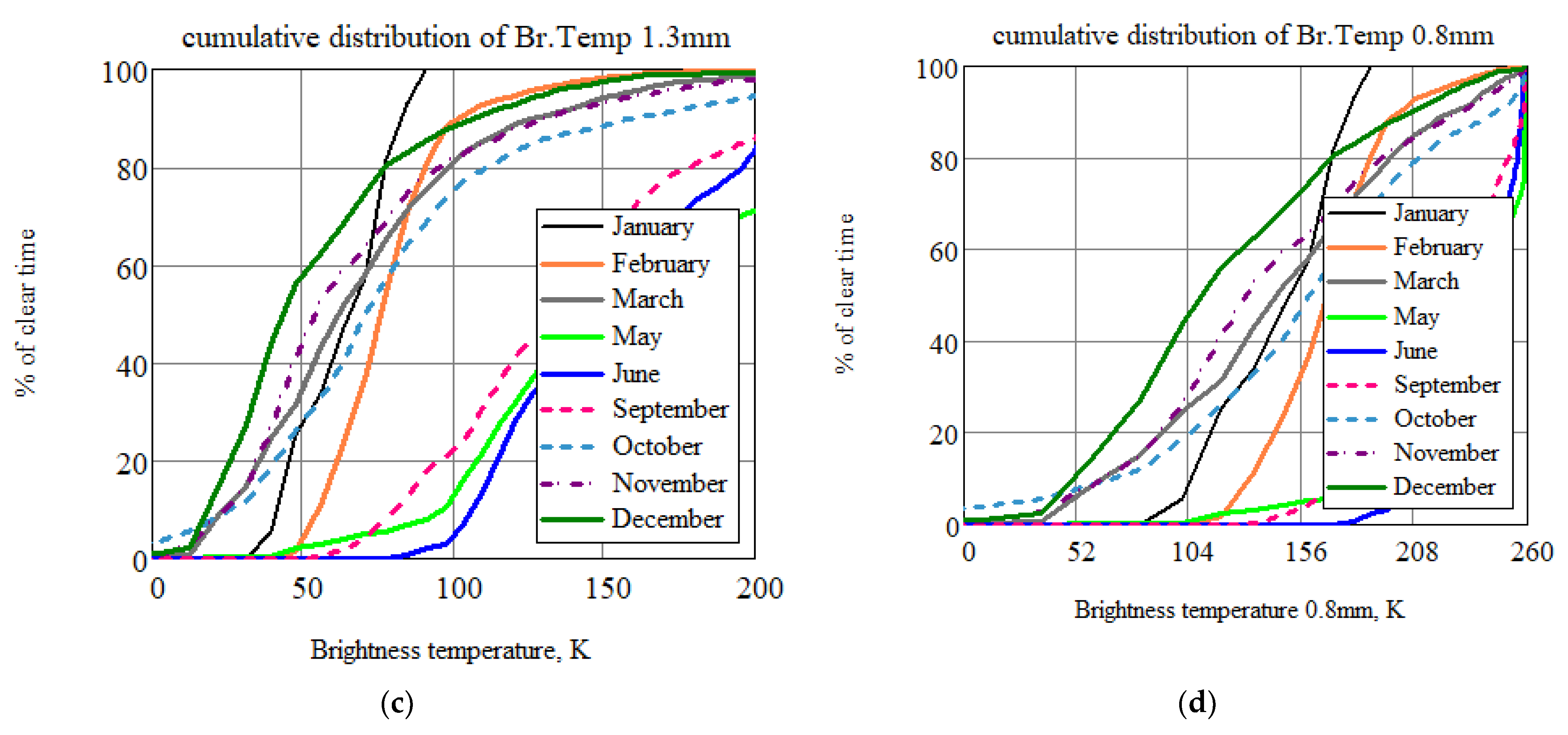
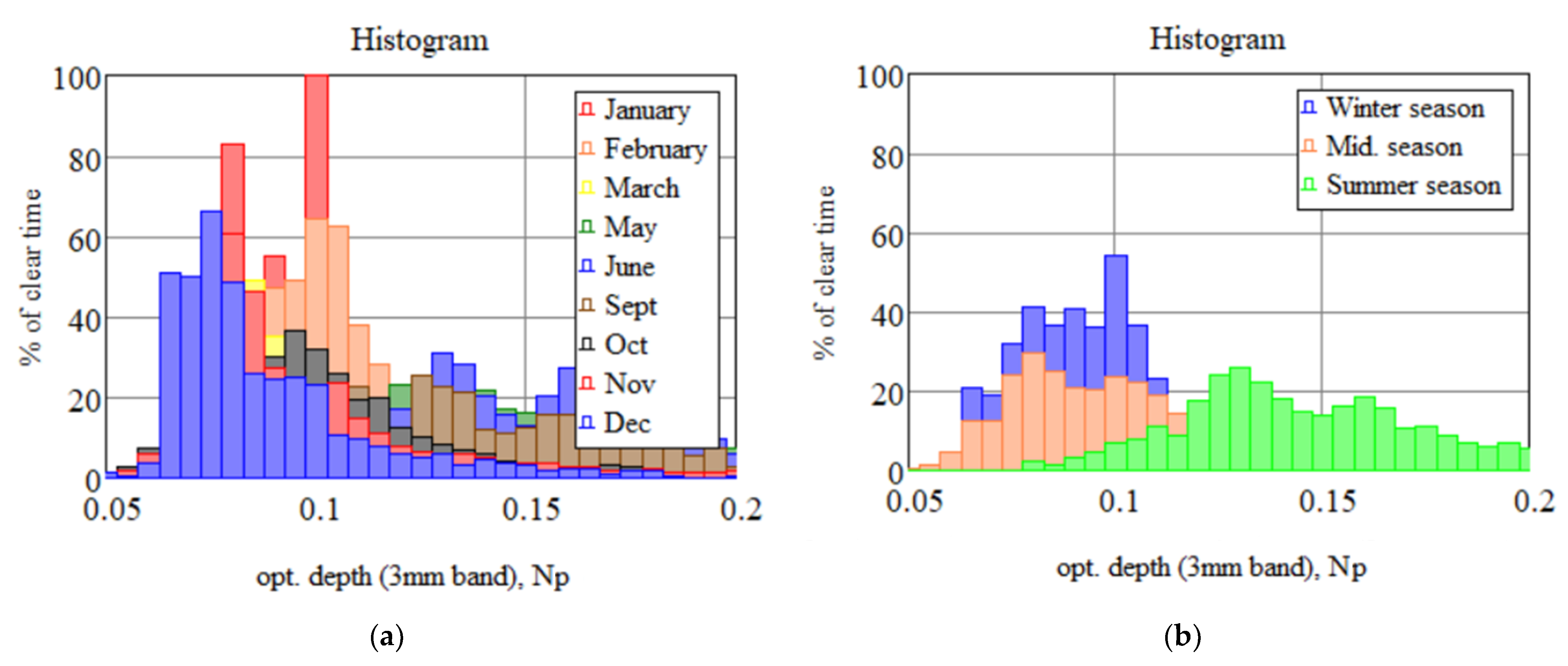
2. Astroclimate Conditions at the BTA Site of the SAO RAS
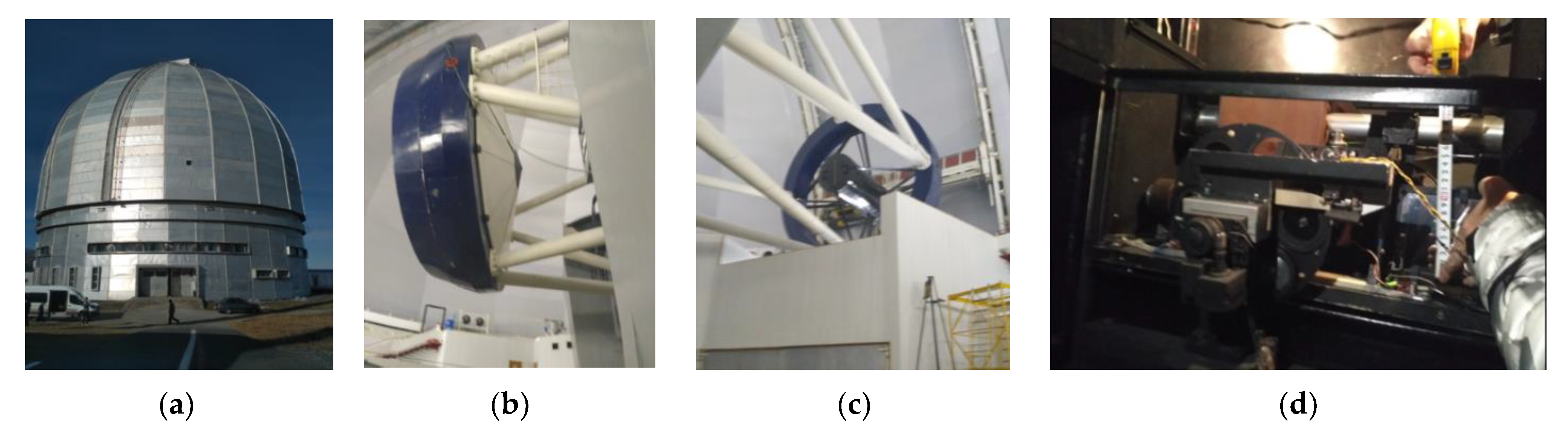
3. Receiving System for the BTA
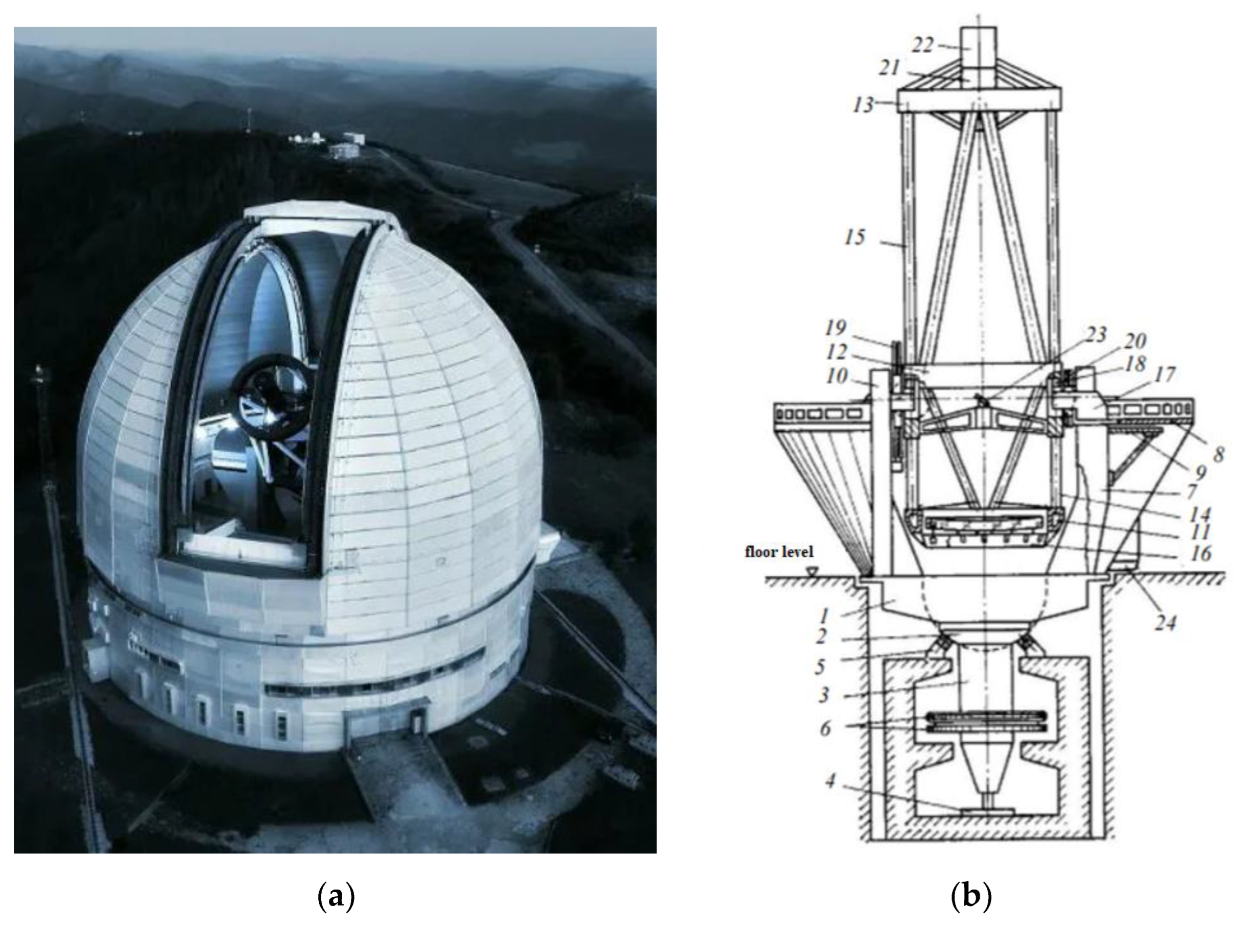
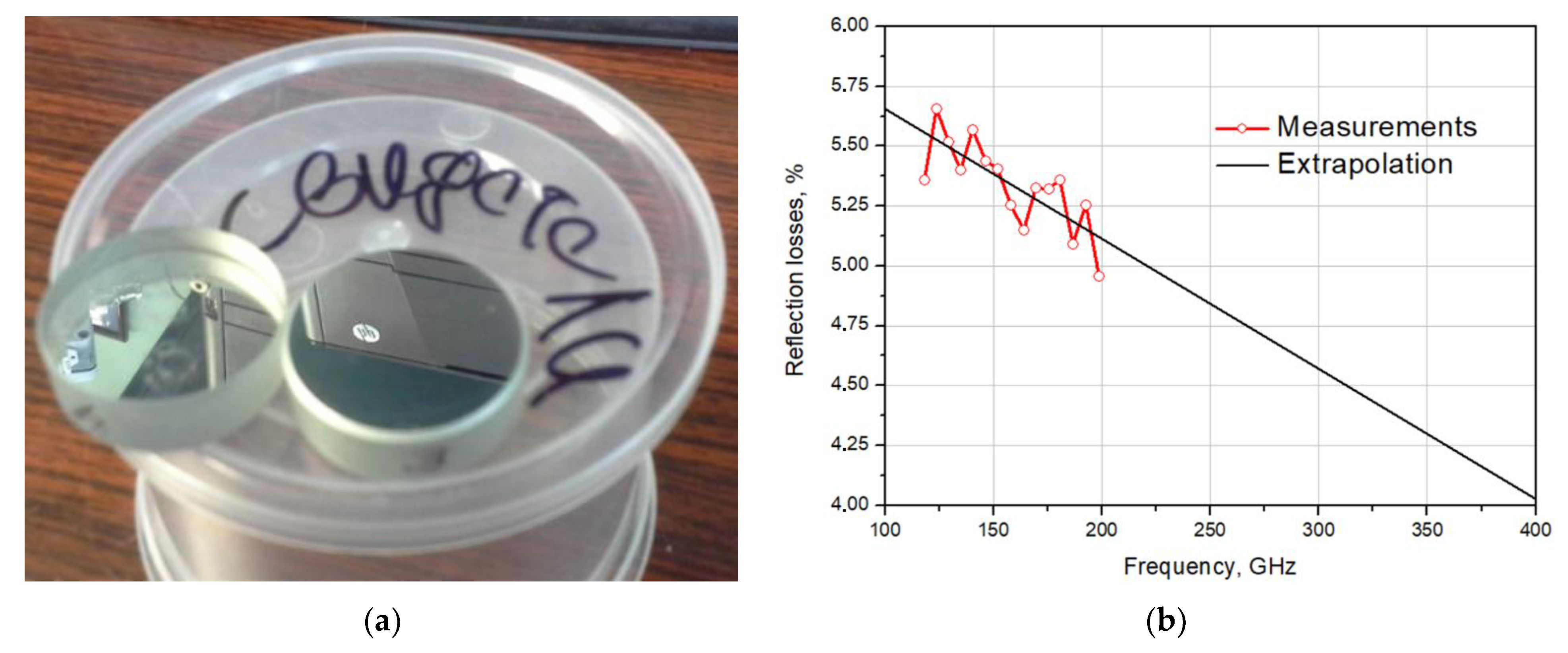
3.1. Surface of the BTA’s Mirror
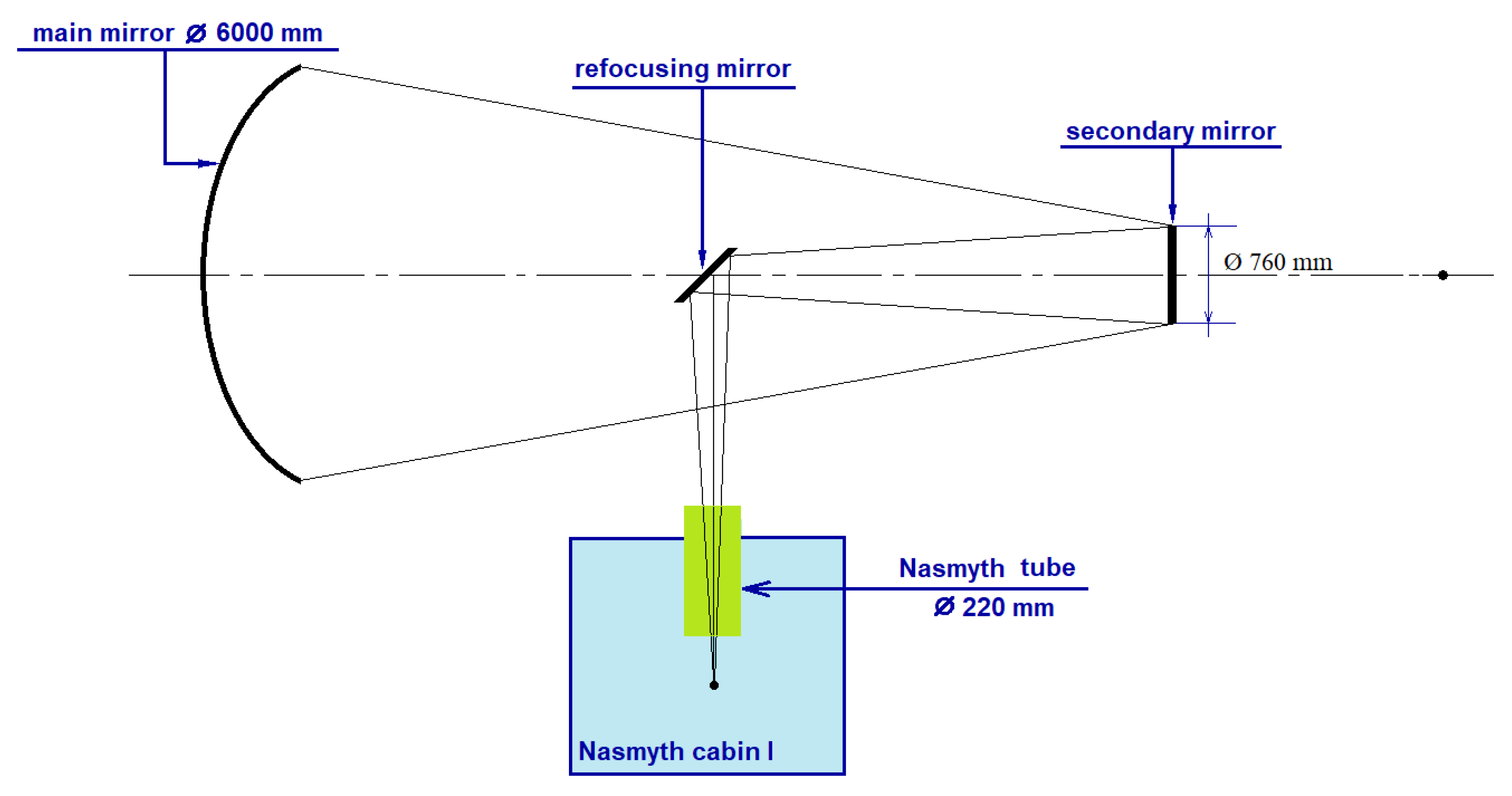
3.2. The Nasmith System of the BTA Telescope
- Quasi-optical calculation method
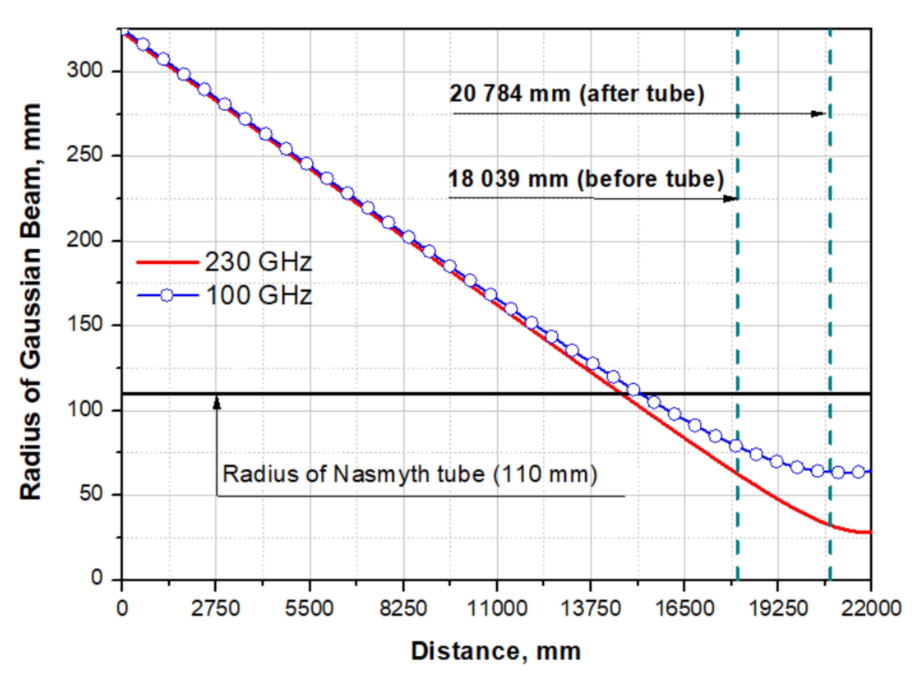
- Calculation of the Gaussian beam radius in the Nasmith 1 scheme of the BTA telescope
- L1 is the distance from the aperture of the horn to the refocusing mirror;
- Fmirr is the focal length of the focusing mirror;
- L2 is the effective focal length of the main mirror.
- Losses during propagation of a Gaussian beam through the “tube”
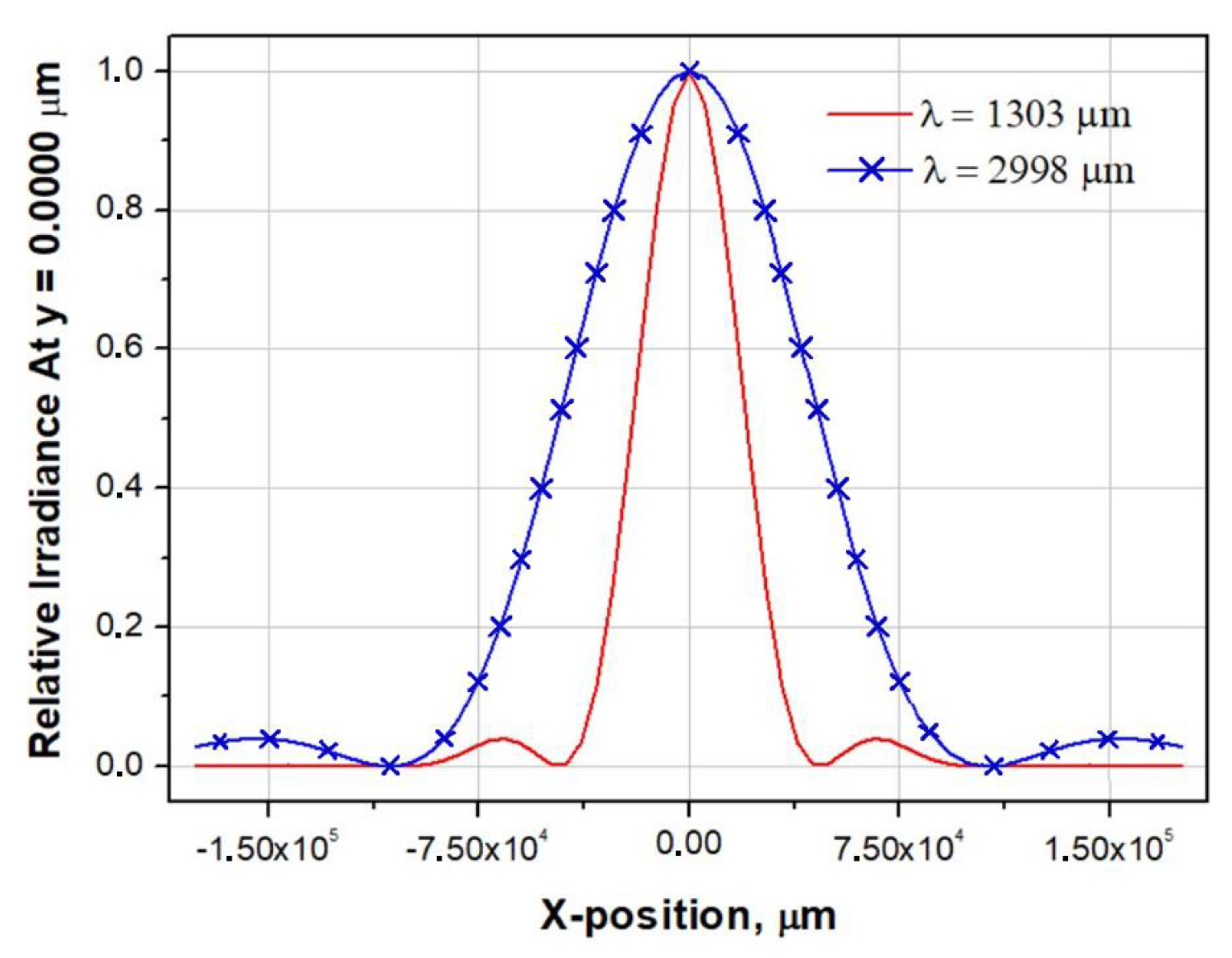
- Calculation in Zemax OpticStudio
- Selection of an astronomical task (depending on this, the central frequency of the signal and the reception bandwidth will be determined, as well as the choice of matching horn, lens, mirror, or horn–lens (mirror) structures);
- Selection of a cryogenic system and determination of its exact overall dimensions (depending on the size and location of the cryostat system, additional mirrors for “transferring” the signal to the cryostat window will be calculated);
- Determination of the maximum permissible diameter of the window in the cryostat through which the signal will be supplied to the detecting device (depending on this size, corrective elements for beam narrowing will be modeled).
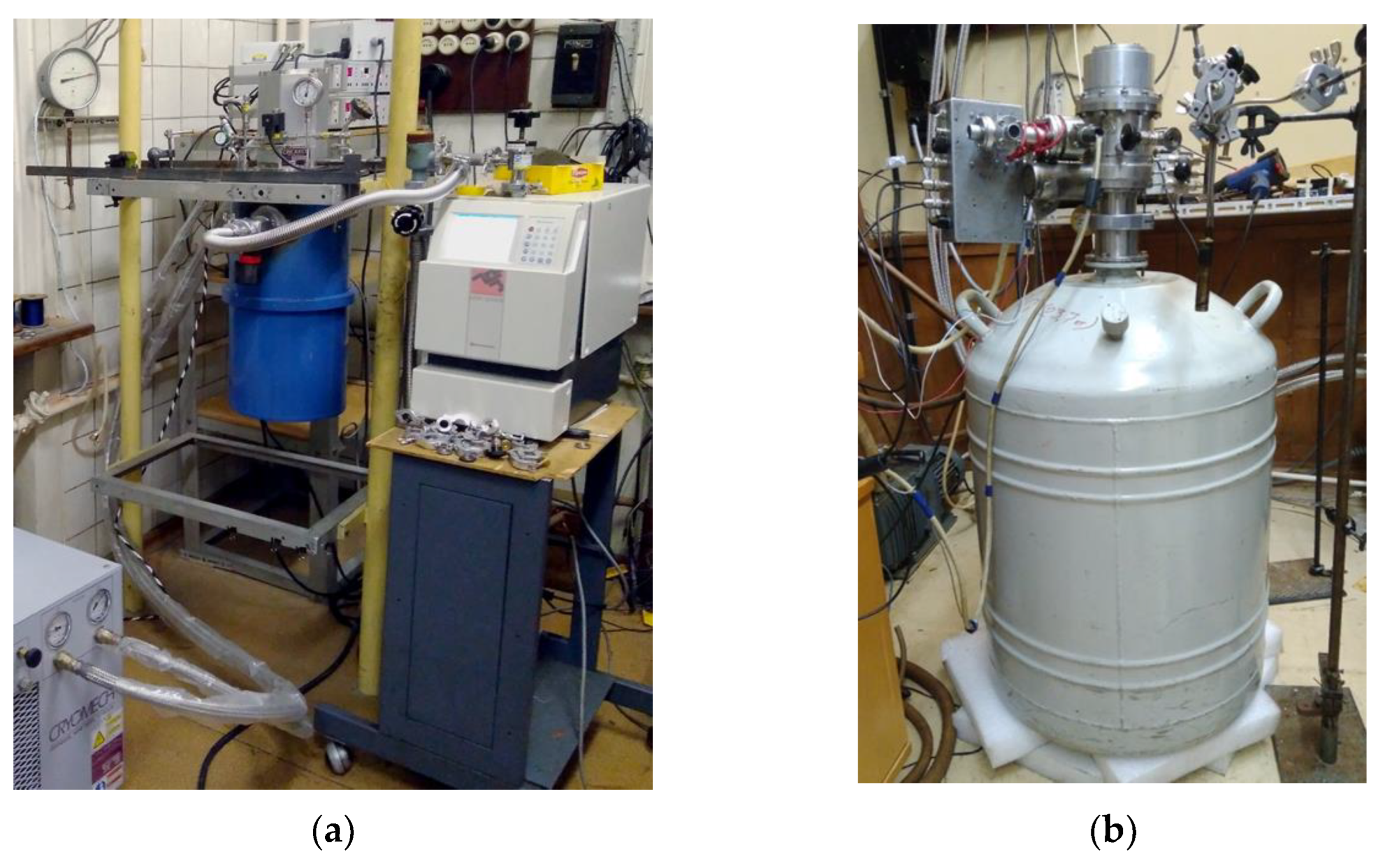
3.3. Cryogenic System
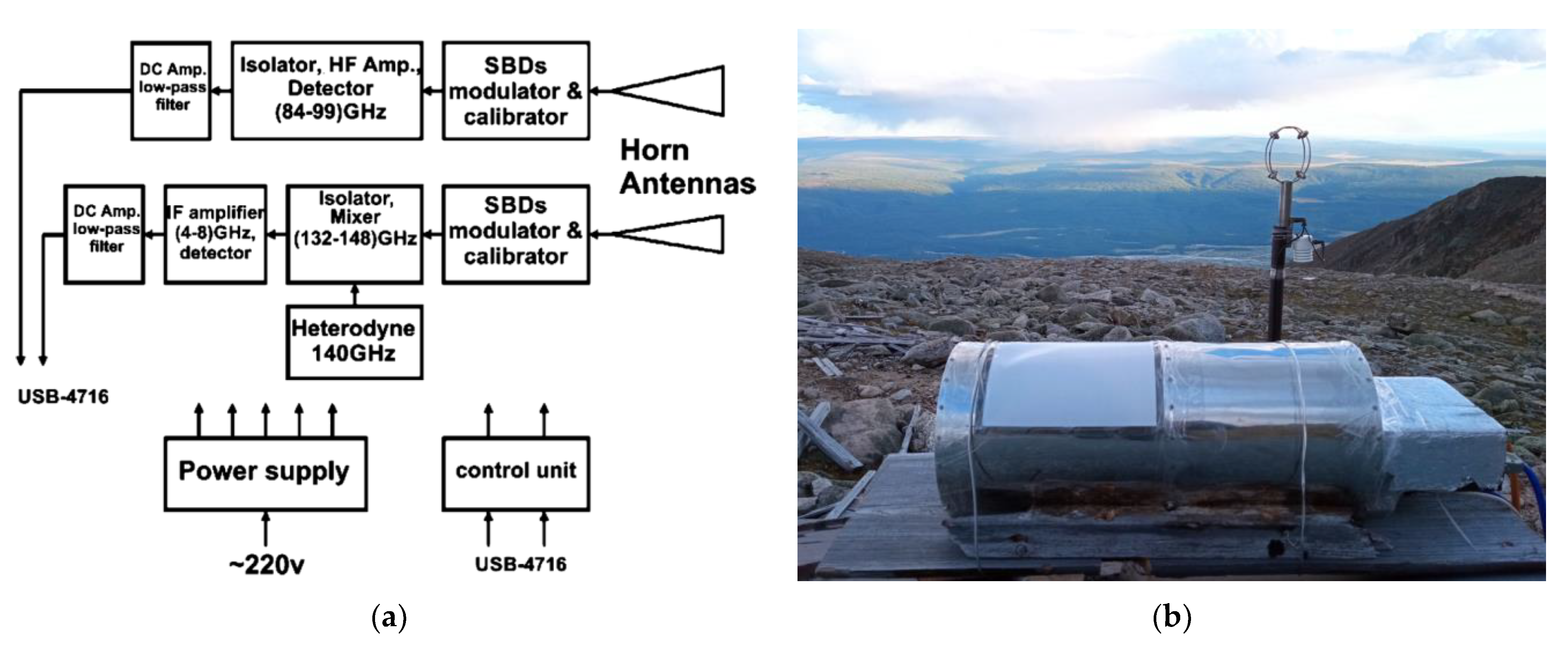
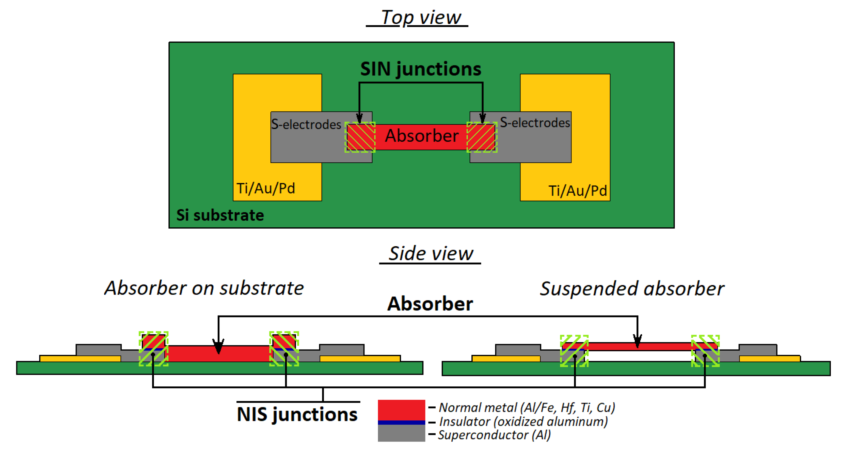
3.4. Detecting Device

3.5. Possible Relevant Astronomical Tasks in the sub-THz Range for the BTA Telescope
- Measurements of the fluxes of bright objects in the continuum by joint programs with the RATAN-600 radio telescope;
- Studies of active galactic nuclei (AGN).
- Studies of lacertids (objects of the BL Lac type);
- Studies of distant quasars (for example, ULIRG QSO);
- Conducting observations of extragalactic objects and molecular clouds in our galaxy in the CO J1-0 115.27 GHz line;
- Estimation of the fluxes of very distant galaxies recently discovered by the JWST Space Telescope (joint optical observation programs with BTA are possible).
4. Conclusions
- This article is in memory of our departed colleagues who make up the history of this project of mounting sub-THz receivers on the site of the BTA optical telescope of the SAO RAS.
Author Contributions
Funding
Institutional Review Board Statement
Informed Consent Statement
Data Availability Statement
Conflicts of Interest
References
- Kislyakov, A.G. Radioastronomical investigations in the millimeter and submillimeter bands. Sov. Phys. Usp. 1971, 13, 495–521. [Google Scholar] [CrossRef]
- Day, P.; Leduc, H.G.; Dowell, C.D.; Lee, R.A.; Turner, A.; Zmuidzinas, J. Distributed Antenna-Coupled TES for FIR Detector Arrays. J. Low Temp. Phys. 2008, 151, 477–482. [Google Scholar] [CrossRef]
- Westbrook, B.; Cukierman, A.; Lee, A.; Suzuki, A.; Raum, C.; Holzapfel, W. Development of the Next Generation of Multichroic Antenna-Coupled Transition Edge Sensor Detectors for CMB Polarimetry. J. Low Temp. Phys. 2016, 184, 74–81. [Google Scholar] [CrossRef]
- Goldie, D.J.; Audley, M.D.; Glowacka, D.M.; Tsaneva, V.N.; Withington, S. Transition edge sensors for bolometric applications: Responsivity and saturation. J. Appl. Phys. 2008, 103, 084509-1–084509-8. [Google Scholar] [CrossRef]
- Hilton, K.D.; Irwin, G.C. Transition-Edge Sensors. In Topics in Applied Physics; Springer: Berlin/Heidelberg, Germany, 2005; Volume 99, pp. 63–150. [Google Scholar]
- Bennett, D.A. Transition-Edge Sensors. In Handbook of Superconductivity, 2nd ed.; Elsevier: Amsterdam, The Netherlands, 2022; ISBN 9781003139638. [Google Scholar]
- Day, P.K.; LeDuk, H.G.; Mazin, B.A.; Vayonakis, A.; Zmuidzinas, J. A broadband superconducting detector suitable for use in large arrays. Nature 2003, 425, 817–821. [Google Scholar] [CrossRef] [PubMed]
- Paiella, A.; Ade, P.A.R.; Battistelli, E.S.; Castellano, M.G.; Colantoni, I.; Columbro, F.; Coppolecchia, A.; D’Alessandro, G.; de Bernardis, P.; De Petris, M.; et al. In Flight Performance of the LEKIDs of the OLIMPO Experiment. J. Low Temp. Phys. 2020, 199, 491–501. [Google Scholar] [CrossRef]
- Nicaise, P. Development of Microwave Kinetic Inductance Detectors for Visible and Near-IR Astronomy Applications. Ph.D. Thesis, Université Paris Sciences et Lettre, Paris, France, 2022. [Google Scholar]
- Brooks, E.; Barry, P.; Nie, R.; Shirokoff, E.; Filippini, J.; Connors, J.; Gradziel, M.; Mercado, D. Development of Microwave Kinetic Inductance Detectors for a THz On-Chip Spectrometer. J. Low Temp. Phys. 2023, preprint. [Google Scholar] [CrossRef]
- ALMA Observatory. Available online: https://www.almaobservatory.org/en/home/ (accessed on 26 December 2023).
- Lundgren, A.; Nyman, L.-A.; Saito, M.; Vilaro, B.V.; Mathys, G.; Andreani, P.; Hibbard, J.; Okumura, S.K.; Tatematsu, K.; Dent, B.; et al. ALMA: The first year of observations. In Proceedings of the SPIE 8448, Observatory Operations: Strategies, Processes, and Systems IV, Amsterdam, The Netherlands, 13 September 2012. [Google Scholar]
- Carlstrom, J.E.; Ade, P.A.R.; Aird, K.A.; Benson, B.A.; Bleem, L.E.; Busetti, S.; Chang, C.L.; Chauvin, E.; Cho, H.-M.; Crawford, T.M.; et al. The 10 Meter South Pole Telescope. Publ. Astron. Soc. Pac. 2011, 123, 568. [Google Scholar] [CrossRef]
- KECK Observatory. Available online: https://keckobservatory.org (accessed on 26 December 2023).
- Lange, A.; Bernardis, P.D.; Petris, M.D.; Masi, S.; Melchiorri, F.; Aquilini, E.; Martinis, L.; Scaramuzzi, F.; Melchiorri, B.; Boscaleri, A.; et al. The BOOMERANG experiment. Space Sci. Rev. 1995, 74, 145–150. [Google Scholar] [CrossRef]
- Nati, F.; Ade, P.; Boscaleri, A.; Brienza, D.; Calvo, M.; Colafrancesco, S.; Conversi, L.; Bernardis, P.D.; Petris, M.D.; Delbart, A.; et al. The OLIMPO experiment. New Astron. Rev. 2007, 51, 385–389. [Google Scholar] [CrossRef]
- Presta, G.; Ade, P.A.R.; Battistelli, E.S.; Castellano, M.G.; Colantoni, I.; Columbro, F.; Coppolecchia, A.; Alessandro, G.D.; Bernardis, P.D.; Gordon, S.; et al. The first flight of the OLIMPO experiment: Instrument performance. J. Phys. Conf. Ser. 2020, 1548, 012018. [Google Scholar] [CrossRef]
- Tauber, J.A. The Planck mission. Adv. Space Res. 2004, 34, 491–496. [Google Scholar] [CrossRef]
- Gardner, J.P.; Mather, J.C.; Clampin, M.; Doyon, R.; Flanagan, K.A.; Franx, M.; Greenhouse, M.A.; Hammel, H.B.; Hutchings, J.B.; Jakobsen, P.; et al. The James Webb Space Telescope. In Astrophysics and Space Science Proceedings (ASSSP); Springer: Berlin/Heidelberg, Germany, 2006; pp. 1–29. [Google Scholar]
- Zinchenko, I.I. Contemporary millimeter and submillimeter-wave astronomy. Radiophys. Quantum Electron. 2003, 46, 577–593. [Google Scholar] [CrossRef]
- Kardashev, N.S.; Novikov, I.D.; Lukash, V.N.; Pilipenko, S.V.; Mikheeva, E.V.; Bisikalo, D.V.; Wiebe, D.S.; Doroshkevich, A.G.; Zasov, A.V.; Zinchenko, I.I.; et al. Review of scientific topics for Millimetron space observatory. Phys. Usp. 2014, 57, 1199–1228. [Google Scholar] [CrossRef]
- Novikov, I.D.; Likhachev, S.F.; Shchekinov, Y.A.; Andrianov, A.S.; Baryshev, A.M.; Vasyunin, A.I.; Wiebe, D.Z.; de Graauw, T.; Doroshkevich, A.G.; Zinchenko, I.I.; et al. Objectives of the Millimetron Space Observatory science program and technical capabilities of its realization. Phys. Usp. 2021, 64, 386–419. [Google Scholar] [CrossRef]
- Institute of Applied Astronomy Russian Academy of Science. Available online: https://iaaras.ru/en/quasar/ (accessed on 30 October 2023).
- Dmitrov Branch of the Bauman Moscow State Technical University. Available online: https://df.bmstu.ru/?p=rt7.5 (accessed on 30 October 2023). (In Russian).
- Hojaev, A.; Shanin, G.I.; Artyomenko, Y. Suffa Radio Observatory in Uzbekistan: Progress and radio-seeing research plans. Proc. Int. Astron. Union 2006, 2, 177–182. [Google Scholar] [CrossRef]
- Special Astrophysical Observatory of Russian Academy of Science. Available online: https://www.sao.ru/Doc-en/Telescopes/bta/descrip.html (accessed on 30 October 2023).
- Bubnov, G.M.; Grigor’ev, V.F.; Zinchenko, I.I.; Zemlyanukha, P.M.; Il’in, G.N.; Kabanov, D.M.; Nosov, V.I.; Vdovin, V.F. Consistent determination of the integral humidity and effective optical depth of the atmosphere in the millimeter wavelength range using wideband radiometers. Radiophys. Quantum Electron. 2020, 62, 820–829. [Google Scholar] [CrossRef]
- Bubnov, G.M.; Abashin, E.B.; Balega, Y.Y.; Bolshakov, O.S.; Dryagin, S.Y.; Dubrovich, V.K.; Marukhno, A.S.; Nocov, V.I.; Vdovin, V.F.; Zinchenko, I.I. Searching for New Sites for THz Observations in Eurasia. IEEE Trans. Terahertz Sci. Technol. 2015, 5, 54–72. [Google Scholar] [CrossRef]
- Shikhovtsev, A.Y.; Kovadlo, P.G.; Khaikin, V.B.; Nosov, V.V.; Lukin, V.P.; Nosov, E.V.; Torgaev, A.V.; Kiselev, A.V.; Shikhovtsev, M.Y. Atmospheric Conditions within Big Telescope Alt-Azimuthal Region and Possibilities of Astronomical Observations. Remote Sens. 2022, 14, 1833. [Google Scholar] [CrossRef]
- Bolbasova, L.A.; Shikhovtsev, A.Y.; Ermakov, S.A. Statistics of precipitable water vapour above the sites of the 6-m Big Telescope Alt-azimuthal and new 3-m Large Solar Telescope using ERA5 data. Mon. Not. R. Astron. Soc. 2023, 520, 4336–4344. [Google Scholar] [CrossRef]
- Shikhovtsev, A.Y.; Khaikin, V.B.; Kovadlo, P.G.; Baron, P. Optical Thickness of the Atmosphere above the Terskol Peak. Atmos. Ocean. Opt. 2023, 36, 78–85. [Google Scholar] [CrossRef]
- Special Astrophysical Observatory of Russian Academy of Science/Mirror Chronicle. Available online: https://www.sao.ru/Doc-en/Events/2018/MirrorChronicle/index.html (accessed on 30 October 2023).
- Parshin, V.V.; Serov, E.A.; Bubnov, G.M.; Vdovin, V.F.; Koshelev, M.A.; Tretyakov, M.Y.C.D. Cryogenic Resonator Complex. Radiophys. Quantum Electron. 2014, 56, 554–560. [Google Scholar] [CrossRef]
- Goldsmith, P.F. Quasi-Optical Techniques. Proc. IEEE 1992, 80, 1729–1747. [Google Scholar] [CrossRef]
- Brückner, C.; Pradarutti, B.; Müller, R.; Riehemann, S.; Notni, G.; Tünnermann, A. Design and evaluation of a THz time domain imaging system using standard optical design software. Appl. Opt. 2008, 47, 4994–5006. [Google Scholar] [CrossRef] [PubMed]
- Jördens, C.; Thorwirth, G.; Koch, M. An optical design for real-time terahertz imaging. In Proceedings of the German Microwave Conference 2006, Karlsruhe, Germany, 28–30 March 2006. [Google Scholar]
- Ladu, A.; Schirru, L.; Gaudiomonte, F.; Marongiu, P.; Angius, G.; Perini, F.; Vargiu, G.P. Upgrading of the L-P Band Cryogenic Receiver of the Sardinia Radio Telescope: A Feasibility Study. Sensors 2022, 22, 4261. [Google Scholar] [CrossRef]
- Ye, Y.; He, L.; Sun, Y.; Zhang, F.; Wang, Z.; Lu, Z.; Zhang, J. Vibration Property of a Cryogenic Optical Resonator within a Pulse-Tube Cryostat. Sensors 2021, 21, 4696. [Google Scholar] [CrossRef] [PubMed]
- Chaudhry, G.; Volpe, A.; Camus, P.; Triqueneaux, S.; Vermeulen, G.-M. A closed-cycle dilution refrigerator for space ap-plications. Cryogenics 2012, 52, 471–477. [Google Scholar] [CrossRef][Green Version]
- Balega, Y.Y.; Bolshakov, O.S.; Chernikov, A. Cryogenic systems for astronomical research in SAO RAS. Opt. Syst. Astron. 2023, 10, 1263. [Google Scholar]
- Devyatov, I.A.; Krutitskiĭ, P.A.; Kupriyanov, M.Y. Investigation of various operation modes of a miniature superconducting detector of microwave radiation. JETP Lett. 2006, 84, 57–61. [Google Scholar] [CrossRef]
- Tarasov, M.; Gunbina, A.; Chekushkin, A.; Ysupov, R.; Edelman, V.; Koshelets, V. Microwave SINIS Detector. Appl. Sci. 2022, 12, 10525. [Google Scholar] [CrossRef]
- Gunbina, A.; Tarasov, M.; Fominsky, M.; Chekushkin, A.; Yusupov, R.; Nagirnaya, D. Fabrication of Aluminium Nanostructures for Microwave Detectors Based on Tunnel Junctions. In Advances in Microelectronics Reviews; Yurish, S.Y., Ed.; IFSA Publishing, S.L.: Barcelona, Spain, 2021; Volume 3, pp. 183–212. [Google Scholar]
- Tarasov, M.; Gunbina, A.; Mahashabde, S.; Ysupov, R.; Chekushkin, A.; Nagirnaya, D.; Edelman, V.; Yakopov, G.; Vdovin, V. Arrays of Annular Antennas with SINIS. IEEE Trans. Appl. Supercond. 2020, 30, 2300106. [Google Scholar] [CrossRef]
- Gunbina, A.A.; Mahashabde, S.; Tarasov, M.; Yakopov, G.; Yusupov, R.; Chekushkin, A.; Nagirnaya, D.V.; Lemzyakov, S.A. A 90 GHz SINIS Detector with 2 GHz Readout. IEEE Trans. Appl. Supercond. 2021, 31, 1500805. [Google Scholar] [CrossRef]
- Dmitriev, P.N.; Filippenko, L.V.; Koshelets, V.P. Josephson Junctions. History, Devices, and Applications; Jenny Stanford Publishing: New York, NY, USA, 2007; pp. 185–244. [Google Scholar] [CrossRef]
- Rudakov, K.I.; Khudchenko, A.V.; Filippenko, L.V.; Paramonov, M.E.; Hesper, R.; da Costa Lima, D.A.R.; Baryshev, A.M.; Koshelets, V.P. THz Range Low-Noise SIS Receivers for Space and Ground-Based Radio Astronomy. Appl. Sci. 2021, 11, 10087. [Google Scholar] [CrossRef]
- Tarasov, M.; Gunbina, A.; Chekushkin, A.; Yusupov, R.; Edelman, V.; Vdovin, V. SINIS detectors: 30 years of achievements and Delusions. In Proceedings of the 2022 IEEE 8th All-Russian Microwave Conference (RMC), Moscow, Russia, 23–25 November 2022; pp. 14–18. [Google Scholar] [CrossRef]


| 100 GHz | 230 GHz | |
|---|---|---|
| Before tube (18,039 mm) | 79.036 mm | 63.08 mm |
| After tube (20,784 mm) | 63.638 mm | 32.148 mm |
| At Nasmyth focus according to Zemax OpticStudio | 80.29 mm | 56.04 mm |
| Percentage of transmitted power | 97.9% | 99.8% |
Disclaimer/Publisher’s Note: The statements, opinions and data contained in all publications are solely those of the individual author(s) and contributor(s) and not of MDPI and/or the editor(s). MDPI and/or the editor(s) disclaim responsibility for any injury to people or property resulting from any ideas, methods, instructions or products referred to in the content. |
© 2024 by the authors. Licensee MDPI, Basel, Switzerland. This article is an open access article distributed under the terms and conditions of the Creative Commons Attribution (CC BY) license (https://creativecommons.org/licenses/by/4.0/).
Share and Cite
Balega, Y.; Bubnov, G.; Chekushkin, A.; Dubrovich, V.; Edelman, V.; Gunbina, A.; Kapustin, S.; Khabarova, T.; Kukushkin, D.; Lapkin, I.; et al. Microwave Receiving System Based on Cryogenic Sensors for the Optical Big Telescope Alt-Azimuth. Sensors 2024, 24, 359. https://doi.org/10.3390/s24020359
Balega Y, Bubnov G, Chekushkin A, Dubrovich V, Edelman V, Gunbina A, Kapustin S, Khabarova T, Kukushkin D, Lapkin I, et al. Microwave Receiving System Based on Cryogenic Sensors for the Optical Big Telescope Alt-Azimuth. Sensors. 2024; 24(2):359. https://doi.org/10.3390/s24020359
Chicago/Turabian StyleBalega, Yurii, Grigory Bubnov, Artem Chekushkin, Victor Dubrovich, Valerian Edelman, Aleksandra Gunbina, Sergey Kapustin, Tatyana Khabarova, Dmitrii Kukushkin, Igor Lapkin, and et al. 2024. "Microwave Receiving System Based on Cryogenic Sensors for the Optical Big Telescope Alt-Azimuth" Sensors 24, no. 2: 359. https://doi.org/10.3390/s24020359
APA StyleBalega, Y., Bubnov, G., Chekushkin, A., Dubrovich, V., Edelman, V., Gunbina, A., Kapustin, S., Khabarova, T., Kukushkin, D., Lapkin, I., Mansfeld, M., Maruhno, A., Parshin, V., Raevskiy, A., Stolyarov, V., Tarasov, M., Valyavin, G., Vdovin, V., Yakopov, G., ... Zinchenko, I. (2024). Microwave Receiving System Based on Cryogenic Sensors for the Optical Big Telescope Alt-Azimuth. Sensors, 24(2), 359. https://doi.org/10.3390/s24020359