Design and Evaluation of a Rapid Monolithic Manufacturing Technique for a Novel Vision-Based Tactile Sensor: C-Sight
Abstract
1. Introduction
1.1. Design Complexity
- Large Category Difference: Different tactile sensing mechanisms rely on distinct hardware structures. For example, GelSight-type sensors [8,18,19] require reflective coatings, whereas marker-based sensors [9,11,20] rely on the marker patterns. The lack of a standardised manufacturing process results in significant disparities in the production of various categories of VBTSs.
- Low Customised Flexibility: The traditional manufacturing methods are usually monofunctional and lack flexibility. For example, the mould-forming method is widely used in elastomer manufacturing for VBTSs. However, modifying the original design of such VBTSs requires additional time for remanufacturing the new mould. This issue, often referred to as the ‘mould dependency’ problem [21], severely restricts design flexibility.
1.2. Process Complexity
- Cumbersome Manufacturing Procedure: The preparation of a single-layer elastomer using the mould-forming method includes multiple steps: mould manufacture, solution preparation, air elimination, mould casting, heat curing, and mould release. Additional procedures, such as dyeing and stiffness adjustment, may also be required, making the procedure more cumbersome.
- Complicated Equipment: With the increase in manufacturing steps, additional specialised equipment becomes necessary. Typically, these devices serve a single manufacturing procedure, posing a significant burden on small or individual research teams.
- Special Manual Skill: Certain manual processes necessitate experience and specialised skills, making them challenging for beginners or other researchers to master. Consequently, this limitation hampers the design sustainability and restricts horizontal collaboration across different research groups.
1.3. Time Complexity
- Long Manufacturing Time: The manufacturing of elastomers involves significant time for preparing, casting, and curing the silicone solution, typically ranging from hours to several days. Similarly, painting coating layers and casting lenses with complex shapes also demands extended time.
- Low Assembly Efficiency: Due to the serial assembly workflow, achieving direct assembly of the final product using all pre-fabricated subparts is challenging. Additionally, the lack of assembly equipment further reduces overall efficiency.
1.4. Quality Complexity
- Large Assembly Errors: Most VBTS manufacturing involves manual assembly, resulting in random assembly errors, which magnify the adverse effects of any existing manufacturing errors.
- Large Individual Variability: Assembly errors can cause output data variations among VBTSs with identical designs. This complicates the generalisation of subsequent signal processing and calibration algorithms, especially for deep learning models.
- We introduce a unified manufacturing framework for VBTS, employing monolithic manufacturing to streamline production and reduce associated costs.
- We develop a novel VBTS sensor, C-Sight, leveraging monolithic manufacturing to demonstrate the adaptability and efficacy of our fabrication method.
2. Design and Fabrication
2.1. Comparison between Typical 3D-Printing Methods
2.2. Monolithic Manufacturing for VBTS
2.2.1. Lens
2.2.2. Elastomer
2.2.3. Coating
2.3. Comparison with Current VBTS Manufacturing
2.4. Design and Fabrication of C-Sight
3. Performance Evaluation
3.1. Evaluation of Monolithic Manufacturing Technology
3.1.1. Print Material
3.1.2. Print Size
3.1.3. Print Capacity
3.2. Evaluation of C-Sight Performance
3.2.1. Manufacturing Performance
3.2.2. Tactile Sensing Performance
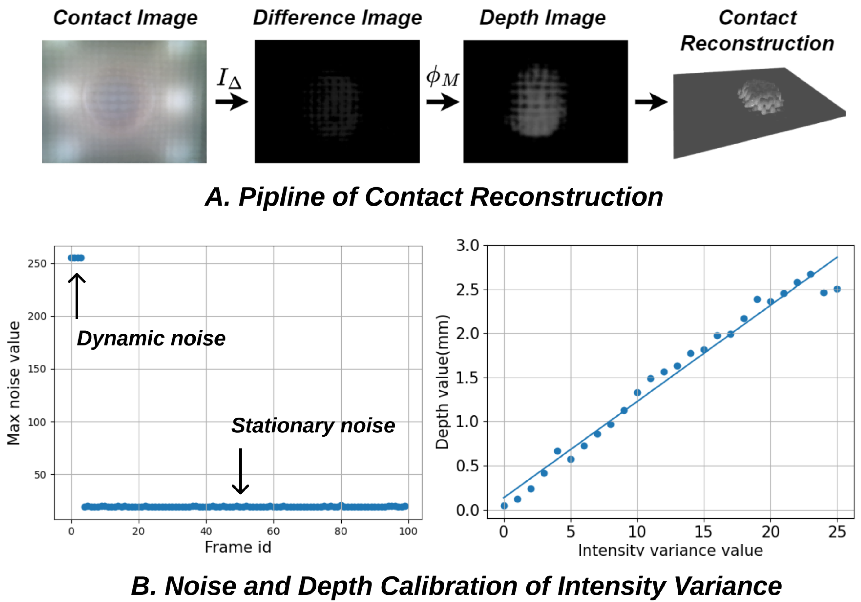
- Intensity Variance Calibration: Noise filtering begins with the captured difference image by identifying two types of noise observed in the initial frames, namely dynamic noise and stationary noise, as shown in Figure 7B, left. Dynamic noise occurs in the first few frames due to camera initialization instability, while stationary noise results from fluctuating errors in sensor hardware, including light source flicker frequency, mounting discrepancies in the contact module, and environmental disturbances. Filtering out these system errors, especially stationary noise, is essential. In our test, stationary noise averages around 20, significantly impacting the data. To avoid that, we discard the first 20 frames upon camera activation to address dynamic noise. Then, the maximum noise observed in the subsequent 100 frames is designated as stationary noise and subtracted from each subsequent frame to generate the depth variance image. The intensity variance calibration process described above executes automatically each time the program initialises. Also, to minimise the dynamic fluctuating of stationary noise over time, adding cooling windows at the sensor base reduces heat build-up, and ensures that the thickness of the sensor base or skin is thick enough to avoid random interference from ambient light, which is easily achieved through the proposed monolithic manufacturing method.
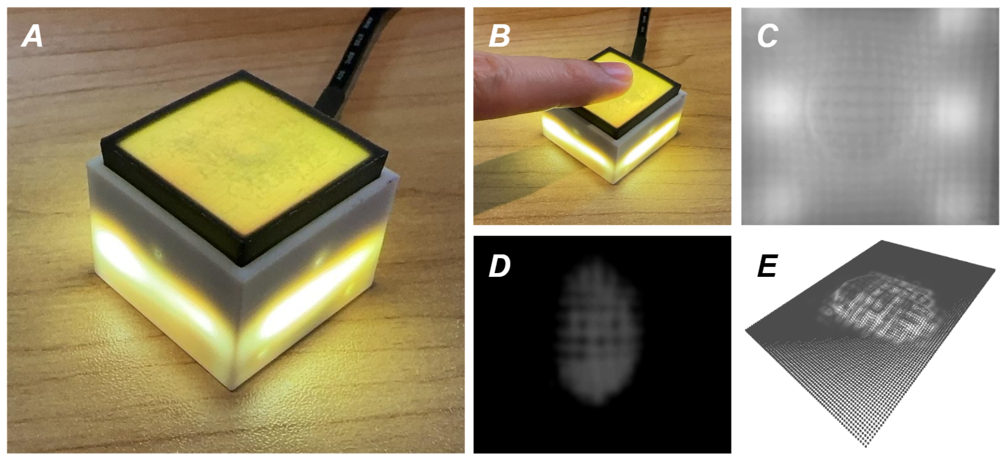
- Depth Mapping Calibration: Following the denoising processes described earlier, the intensity-to-depth calibration is performed using Equation (2). In this calibration step, C-Sight is brought into contact with a 6 mm diameter iron ball to establish depth calibration. Given the focus of this paper on verifying the feasibility of C-Sight through monolithic manufacturing, depth calibration is simplified by focusing solely on the center of the sensor surface rather than the entire area. This approach may introduce some distortion at the corners but remains acceptable for functional verification purposes. One example of the depth calibration results is shown in Figure 7B. The mapping regression between depth and intensity variance value is close to the linear relationship, with a depth range of mm and an intensity variance value range of [0, 25]. Unlike the automatic process of intensity variance calibration, depth calibration involves manual operation. It is typically performed when C-Sight is initially assembled or when a new contact module is installed. The resulting regression data from the calibration process is stored in a retrievable file format for future use
4. Conclusions and Future Work
Author Contributions
Funding
Institutional Review Board Statement
Informed Consent Statement
Data Availability Statement
Acknowledgments
Conflicts of Interest
References
- Lin, Y.; Church, A.; Yang, M.; Li, H.; Lloyd, J.; Zhang, D.; Lepora, N.F. Bi-touch: Bimanual tactile manipulation with sim-to-real deep reinforcement learning. IEEE Robot. Autom. Lett. 2023, 8, 5472–5479. [Google Scholar] [CrossRef]
- Wang, H.; De Boer, G.; Kow, J.; Alazmani, A.; Ghajari, M.; Hewson, R.; Culmer, P. Design methodology for magnetic field-based soft tri-axis tactile sensors. Sensors 2016, 16, 1356. [Google Scholar] [CrossRef] [PubMed]
- Hu, H.; Zhang, C.; Pan, C.; Dai, H.; Sun, H.; Pan, Y.; Lai, X.; Lyu, C.; Tang, D.; Fu, J.; et al. Wireless flexible magnetic tactile sensor with super-resolution in large-areas. ACS Nano 2022, 16, 19271–19280. [Google Scholar] [CrossRef]
- Li, T.; Luo, H.; Qin, L.; Wang, X.; Xiong, Z.; Ding, H.; Gu, Y.; Liu, Z.; Zhang, T. Flexible capacitive tactile sensor based on micropatterned dielectric layer. Small 2016, 12, 5042–5048. [Google Scholar] [CrossRef]
- Kim, H.K.; Lee, S.; Yun, K.S. Capacitive tactile sensor array for touch screen application. Sens. Actuators A Phys. 2011, 165, 2–7. [Google Scholar] [CrossRef]
- Zhu, Y.; Liu, Y.; Sun, Y.; Zhang, Y.; Ding, G. Recent advances in resistive sensor technology for tactile perception: A review. IEEE Sens. J. 2022, 22, 15635–15649. [Google Scholar] [CrossRef]
- Meng, H.; Zhou, L.; Qian, X.; Bao, G. Design and application of flexible resistive tactile sensor based on short-circuit effect. IEEE Trans. Instrum. Meas. 2022, 72, 1–8. [Google Scholar] [CrossRef]
- Yuan, W.; Dong, S.; Adelson, E.H. Gelsight: High-resolution robot tactile sensors for estimating geometry and force. Sensors 2017, 17, 2762. [Google Scholar] [CrossRef] [PubMed]
- Ward-Cherrier, B.; Pestell, N.; Cramphorn, L.; Winstone, B.; Giannaccini, M.E.; Rossiter, J.; Lepora, N.F. The tactip family: Soft optical tactile sensors with 3d-printed biomimetic morphologies. Soft Robot. 2018, 5, 216–227. [Google Scholar] [CrossRef] [PubMed]
- Lin, C.; Lin, Z.; Wang, S.; Xu, H. DTact: A vision-based tactile sensor that measures high-resolution 3d geometry directly from darkness. In Proceedings of the 2023 IEEE International Conference on Robotics and Automation (ICRA), London, UK, 29 May–2 June 2023; pp. 10359–10366. [Google Scholar]
- Li, H.; Nam, S.; Lu, Z.; Yang, C.; Psomopoulou, E.; Lepora, N.F. BioTacTip: A Soft Biomimetic Optical Tactile Sensor for Efficient 3D Contact Localization and 3D Force Estimation. IEEE Robot. Autom. Lett. 2024, 9, 5314–5321. [Google Scholar] [CrossRef]
- Fan, W.; Li, H.; Si, W.; Luo, S.; Lepora, N.F.; Zhang, D. ViTacTip: Design and Verification of a Novel Biomimetic Physical Vision-Tactile Fusion Sensor. arXiv 2024, arXiv:2402.00199. [Google Scholar]
- Fan, W.; Yang, M.; Xing, Y.; Lepora, N.F.; Zhang, D. Tac-VGNN: A Voronoi Graph Neural Network for Pose-Based Tactile Servoing. In Proceedings of the 2023 IEEE International Conference on Robotics and Automation (ICRA), London, UK, 29 May–2 June 2023; pp. 10373–10379. [Google Scholar]
- Lin, C.; Zhang, H.; Xu, J.; Wu, L.; Xu, H. 9DTact: A Compact Vision-Based Tactile Sensor for Accurate 3D Shape Reconstruction and Generalizable 6D Force Estimation. IEEE Robot. Autom. Lett. 2023, 9, 923–930. [Google Scholar] [CrossRef]
- Yamaguchi, A. FingerVision with whiskers: Light touch detection with vision-based tactile sensors. In Proceedings of the 2021 Fifth IEEE International Conference on Robotic Computing (IRC), Taichung, Taiwan, 15–17 November 2021; pp. 56–64. [Google Scholar]
- Zhang, S.; Chen, Z.; Gao, Y.; Wan, W.; Shan, J.; Xue, H.; Sun, F.; Yang, Y.; Fang, B. Hardware technology of vision-based tactile sensor: A review. IEEE Sens. J. 2022. [Google Scholar] [CrossRef]
- Azulay, O.; Curtis, N.; Sokolovsky, R.; Levitski, G.; Slomovik, D.; Lilling, G.; Sintov, A. Allsight: A low-cost and high-resolution round tactile sensor with zero-shot learning capability. IEEE Robot. Autom. Lett. 2023, 9, 483–490. [Google Scholar] [CrossRef]
- Wang, S.; She, Y.; Romero, B.; Adelson, E. Gelsight wedge: Measuring high-resolution 3d contact geometry with a compact robot finger. In Proceedings of the 2021 IEEE International Conference on Robotics and Automation (ICRA), Xi’an, China, 30 May–5 June 2021; pp. 6468–6475. [Google Scholar]
- Taylor, I.H.; Dong, S.; Rodriguez, A. Gelslim 3.0: High-resolution measurement of shape, force and slip in a compact tactile-sensing finger. In Proceedings of the 2022 International Conference on Robotics and Automation (ICRA), Philadelphia, PA, USA, 23–27 May 2022; pp. 10781–10787. [Google Scholar]
- Vlack, K.; Mizota, T.; Kawakami, N.; Kamiyama, K.; Kajimoto, H.; Tachi, S. GelForce: A vision-based traction field computer interface. In Proceedings of the CHI’05 Extended Abstracts on Human Factors in Computing Systems, Minato, Japan, 18–19 November 2004; pp. 1154–1155. [Google Scholar]
- Fan, W.; Li, H.; Zhang, D. MagicTac: A Novel High-Resolution 3D Multi-layer Grid-Based Tactile Sensor. arXiv 2024, arXiv:2402.01366. [Google Scholar]
- Scharff, R.B.; Boonstra, D.J.; Willemet, L.; Lin, X.; Wiertlewski, M. Rapid manufacturing of color-based hemispherical soft tactile fingertips. In Proceedings of the 2022 IEEE 5th International Conference on Soft Robotics (RoboSoft), Edinburgh, UK, 4–8 April 2022; pp. 896–902. [Google Scholar]
- Muthuram, N.; Madhav, P.S.; Vasan, D.K.; Mohan, M.E.; Prajeeth, G. A review of recent literatures in poly jet printing process. Mater. Today Proc. 2022, 68, 1906–1920. [Google Scholar] [CrossRef]
- Popescu, D.; Zapciu, A.; Amza, C.; Baciu, F.; Marinescu, R. FDM process parameters influence over the mechanical properties of polymer specimens: A review. Polym. Test. 2018, 69, 157–166. [Google Scholar] [CrossRef]
- Huang, J.; Qin, Q.; Wang, J. A review of stereolithography: Processes and systems. Processes 2020, 8, 1138. [Google Scholar] [CrossRef]
- Kafle, A.; Luis, E.; Silwal, R.; Pan, H.M.; Shrestha, P.L.; Bastola, A.K. 3D/4D Printing of polymers: Fused deposition modelling (FDM), selective laser sintering (SLS), and stereolithography (SLA). Polymers 2021, 13, 3101. [Google Scholar] [CrossRef] [PubMed]
- Li, M.; Li, T.; Jiang, Y. Marker Displacement Method Used in Vision-Based Tactile Sensors—From 2D to 3D-A Review. IEEE Sens. J. 2023, 23, 8042–8059. [Google Scholar] [CrossRef]


| Technology | Layer Height | Surface Finish | Multi-Material | Transparent * | Flexible * | Post Process | Material Cost | Device Cost |
|---|---|---|---|---|---|---|---|---|
| FDM [24] | 0.05∼0.3 mm | Low | ✓ | ✓ | x | Complex | Low | Low |
| SLA [25] | 0.025∼0.1 mm | Extra Fine | x | ✓ | ✓ | Complex | High | High |
| SLS [26] | 0.05∼0.2 mm | Rough | x | x | x | Easy | Low | High |
| PP [23] | ∼0.016 mm | Fine | ✓ | ✓ | ✓ | Easy | High | High |
| Material | Color | Stiffness | Attribute | Potential |
|---|---|---|---|---|
| Vero | Clear/Multi-color | Rigid | Resin-like, unlimited full-color tints by mixing | Base/Lens/Marker |
| Agilus30 | Clear/White/Black | Flexible | Rubber-like, adjustable color and stiffness (≥Shore 30A) | Skin/Elastomer/Marker |
| Tango | Translucent/Gray/Black | Flexible | Rubber-like, adjustable color and stiffness (≥Shore 27A) | Skin/Marker |
| Support | Translucent | Ultra-soft | Gel-like, with rigid grid, hands-free/mechanical removal | Elastomer |
| DraftGrey | Multi-color | Rigid | Resin-like, with medium opacity, cheapest and fastest | Base |
| Digital ABS | Multi-color | Rigid | Resin-like, high temperature resistance and toughness | Base |
| Material | AB (g) | AW (g) | AC (g) | DG (g) | VB (g) | VW (g) | VC (g) | Sup (g) | Time (min) | Cost (£) 1 | T/V (min/cm3) | C/V (£/cm3) 1 |
|---|---|---|---|---|---|---|---|---|---|---|---|---|
| AB | 8 | 1 | 1 | 2 | 1 | 1 | 1 | 5 | 32 | 3.002 | 7.11 | 0.667 |
| AW | 1 | 8 | 1 | 2 | 1 | 1 | 1 | 4 | 32 | 2.932 | 7.11 | 0.652 |
| AC | 1 | 1 | 8 | 2 | 1 | 1 | 1 | 4 | 32 | 2.932 | 7.11 | 0.652 |
| DG | 1 | 1 | 1 | 8 | 1 | 1 | 1 | 2 | 24 | 1.908 | 5.33 | 0.424 |
| VB | 1 | 1 | 1 | 1 | 8 | 1 | 1 | 2 | 24 | 2.426 | 5.33 | 0.539 |
| VW | 1 | 1 | 1 | 1 | 1 | 8 | 1 | 2 | 24 | 2.426 | 5.33 | 0.539 |
| VC | 1 | 1 | 1 | 1 | 1 | 1 | 8 | 2 | 24 | 2.426 | 5.33 | 0.539 |
| Hybrid | 2 | 2 | 2 | 2 | 2 | 2 | 2 | 5 | 32 | 2.682 | 7.11 | 0.596 |
| Size X/Y/Z (mm) | Time (min) | T/V (min/cm3) | C/V (£/cm3) |
|---|---|---|---|
| 10 × 30 ×5 | 29 | 19.33 | 1.137 |
| 20 × 30 × 5 | 31 | 10.33 | 0.792 |
| 30 × 30 × 5 (X) | 32 | 7.11 | 0.596 |
| 30 × 10 × 5 | 30 | 20.0 | 1.111 |
| 30 × 20 × 5 | 32 | 10.67 | 0.722 |
| 30 × 30 × 5 (Y) | 32 | 7.11 | 0.632 |
| 30 × 30 × 10 | 51 | 5.67 | 0.573 |
| 30 × 30 × 15 | 69 | 5.11 | 0.462 |
| 30 × 30 × 20 | 89 | 4.94 | 0.521 |
| 30 × 30 × 25 | 110 | 4.89 | 0.514 |
| 30 × 30 × 30 | 128 | 4.74 | 0.479 |
| Capacity X/Y | Time (min) | T/V (min/cm3) | C/V (£/cm3) |
|---|---|---|---|
| 1 × 1 | 32 | 7.11 | 0.596 |
| 2 × 1 | 33 | 3.67 | 0.459 |
| 3 × 1 | 35 | 2.59 | 0.454 |
| 4 × 1 | 37 | 2.06 | 0.413 |
| 5 × 1 | 39 | 1.73 | 0.402 |
| 6 × 1 | 40 | 1.48 | 0.392 |
| 7 × 1 | 41 | 1.30 | 0.375 |
| 1 × 2 | 70 | 7.78 | 0.596 |
| 1 × 3 | 72 | 5.33 | 0.546 |
| 1 × 4 | 110 | 6.11 | 0.634 |
| 1 × 5 | 110 | 4.89 | 0.575 |
| 1 × 6 | 147 | 5.44 | 0.575 |
| 1 × 7 | 184 | 5.84 | 0.599 |
| 7 × 7 Diagonal | 233 | 7.4 | 0.678 |
| 7 × 7 Maximum | 233 | 1.06 | 0.382 |
| Sensor | Size X/Y/Z (mm) | Volume (cm3) | AG (g) | VR (g) | DG (g) | Sup (g) | Time (min) | Cost (£) 1 | T/V (min/cm3) | C/V (£/cm3) 1 |
|---|---|---|---|---|---|---|---|---|---|---|
| C-Sight | 26.5 × 26.5 × 13.5 | 6.446 | 10 | 10 | 3 | 8 | 64 | 4.418 | 9.929 | 0.685 |
Disclaimer/Publisher’s Note: The statements, opinions and data contained in all publications are solely those of the individual author(s) and contributor(s) and not of MDPI and/or the editor(s). MDPI and/or the editor(s) disclaim responsibility for any injury to people or property resulting from any ideas, methods, instructions or products referred to in the content. |
© 2024 by the authors. Licensee MDPI, Basel, Switzerland. This article is an open access article distributed under the terms and conditions of the Creative Commons Attribution (CC BY) license (https://creativecommons.org/licenses/by/4.0/).
Share and Cite
Fan, W.; Li, H.; Xing, Y.; Zhang, D. Design and Evaluation of a Rapid Monolithic Manufacturing Technique for a Novel Vision-Based Tactile Sensor: C-Sight. Sensors 2024, 24, 4603. https://doi.org/10.3390/s24144603
Fan W, Li H, Xing Y, Zhang D. Design and Evaluation of a Rapid Monolithic Manufacturing Technique for a Novel Vision-Based Tactile Sensor: C-Sight. Sensors. 2024; 24(14):4603. https://doi.org/10.3390/s24144603
Chicago/Turabian StyleFan, Wen, Haoran Li, Yifan Xing, and Dandan Zhang. 2024. "Design and Evaluation of a Rapid Monolithic Manufacturing Technique for a Novel Vision-Based Tactile Sensor: C-Sight" Sensors 24, no. 14: 4603. https://doi.org/10.3390/s24144603
APA StyleFan, W., Li, H., Xing, Y., & Zhang, D. (2024). Design and Evaluation of a Rapid Monolithic Manufacturing Technique for a Novel Vision-Based Tactile Sensor: C-Sight. Sensors, 24(14), 4603. https://doi.org/10.3390/s24144603


