Design and Implementation of a Hybrid Optical Camera Communication System for Indoor Applications


Abstract
1. Introduction
- Visible light waves do not harm human health if appropriate dimming and non-flicker methods are used. As mentioned in some results based on human health [2], if the optical modulation frequency exceeds 200 Hz, there is no adverse impact on human eyes.
- The visible light bandwidth is 1000 times larger than the RF bandwidth.
- VLC is more cost-efficient than RF communication; because visible light already exists in the light infrastructure of streets and vehicles, the implementation cost is lower [3].
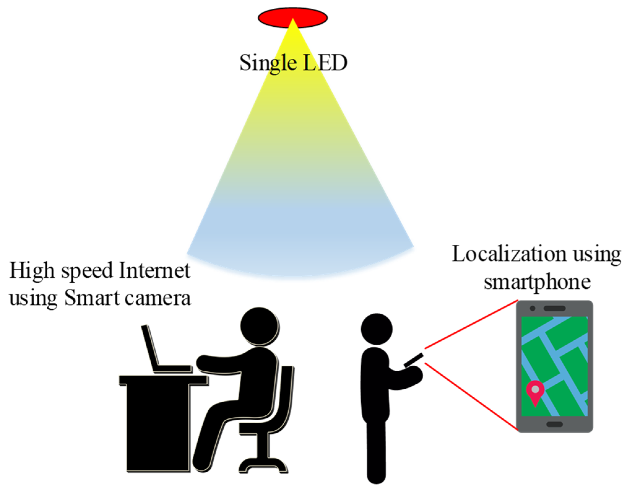
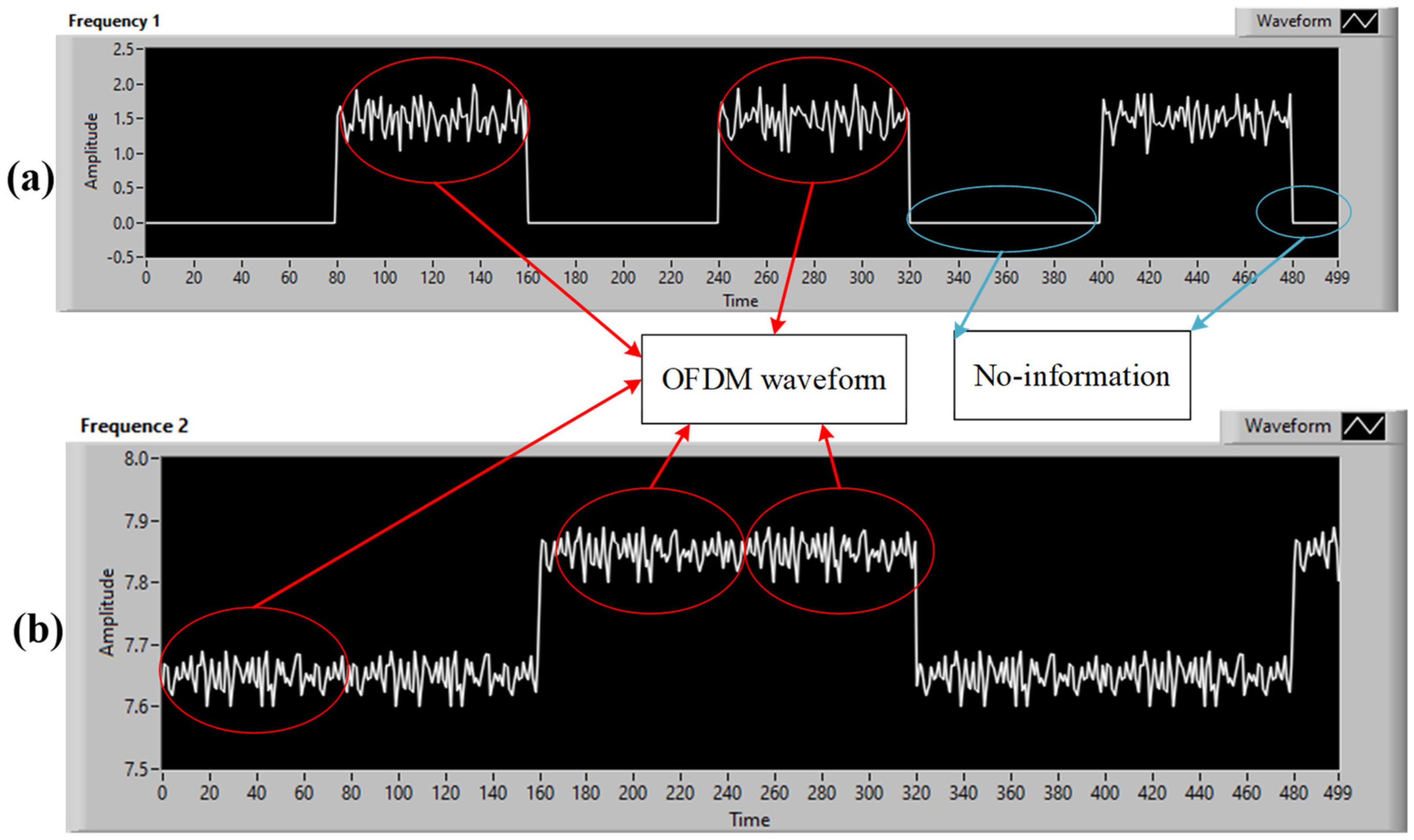
- It contains a proposal for a new hybrid waveform combining two types of OCC waveforms, a low frame-rate stream and a high frame-rate stream, that are transmitted from a single LED. The two signals are transmitted simultaneously through the same optical channel with varying data rates by combining the two waveforms. Therefore, two different pieces of information from the two systems can be easily transmitted at the same time.
- Increased throughput: The total throughput of the proposed hybrid scheme is calculated by summing the individual throughputs from the two waveforms. The throughput is thus improved when compared with those of conventional schemes.
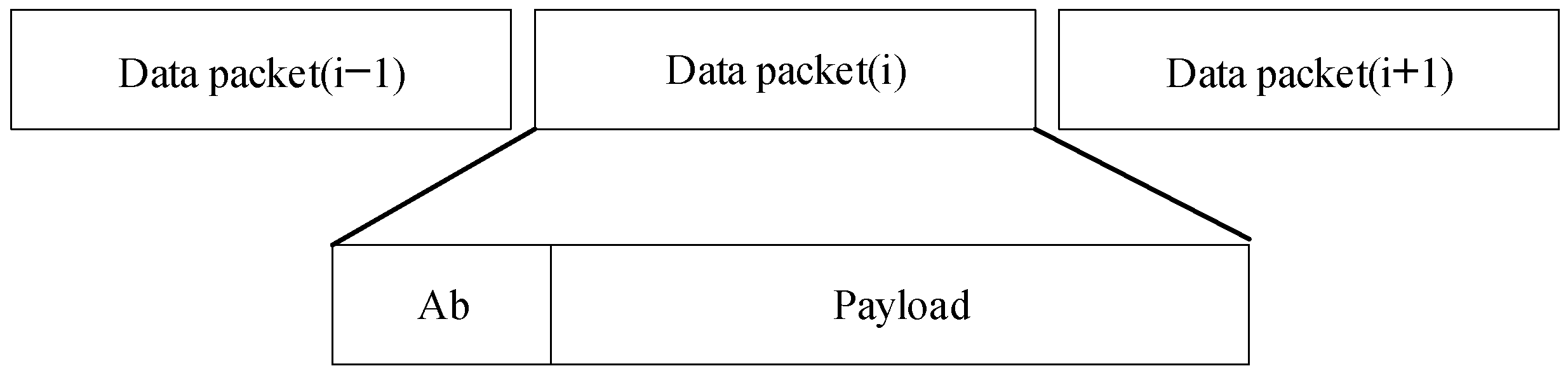
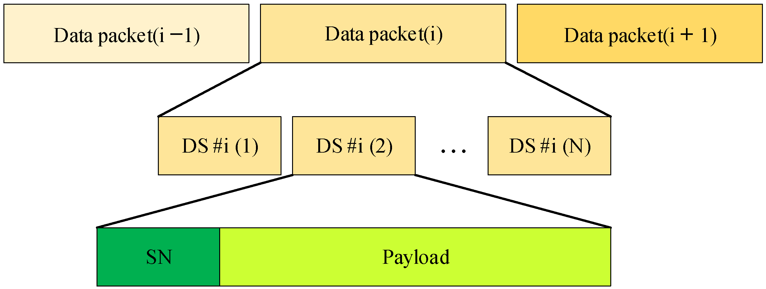
- Support for frame-rate variation: In an OCC system, frame-rate variation can be quite unpredictable. While many assume that a camera’s frame rate is fixed, such as 30 fps or 1000 fps, each camera has a unique frame rate that is determined by its technical parameters. This variability adds complexity to the task of synchronizing the transmission (Tx) and reception (Rx). However, by utilizing the sequence number in the OFDM scheme and employing the Ab bit in the FSK scheme [5], any receiver with a frame rate greater than the transmitter’s packet rate can easily decode data by checking the sequence number value.
- Data merger algorithm: The sequence number and Ab bit support to address frame-rate variation and advance the OCC performance. This idea is to merge the packages into a whole data sequence in the right order.
- By using a single LED to transmit two different data streams, we can reduce cost while providing various services to users through low-complexity light sources in the communication network.
- Detecting missing packets: When the sequence number length in the OFDM scheme exceeds a certain threshold, it becomes simple to detect any missing packets by comparing the sequence numbers of two consecutive images captured by the camera.
- In an OCC system, it can be challenging to deal with complex noise, which includes issues like blurred images, interference, and irregular signal attenuation in the time domain. Nonetheless, these problems can be effectively addressed in the frequency domain by excluding the DC component of the high data-rate stream using the RS-OFDM scheme.
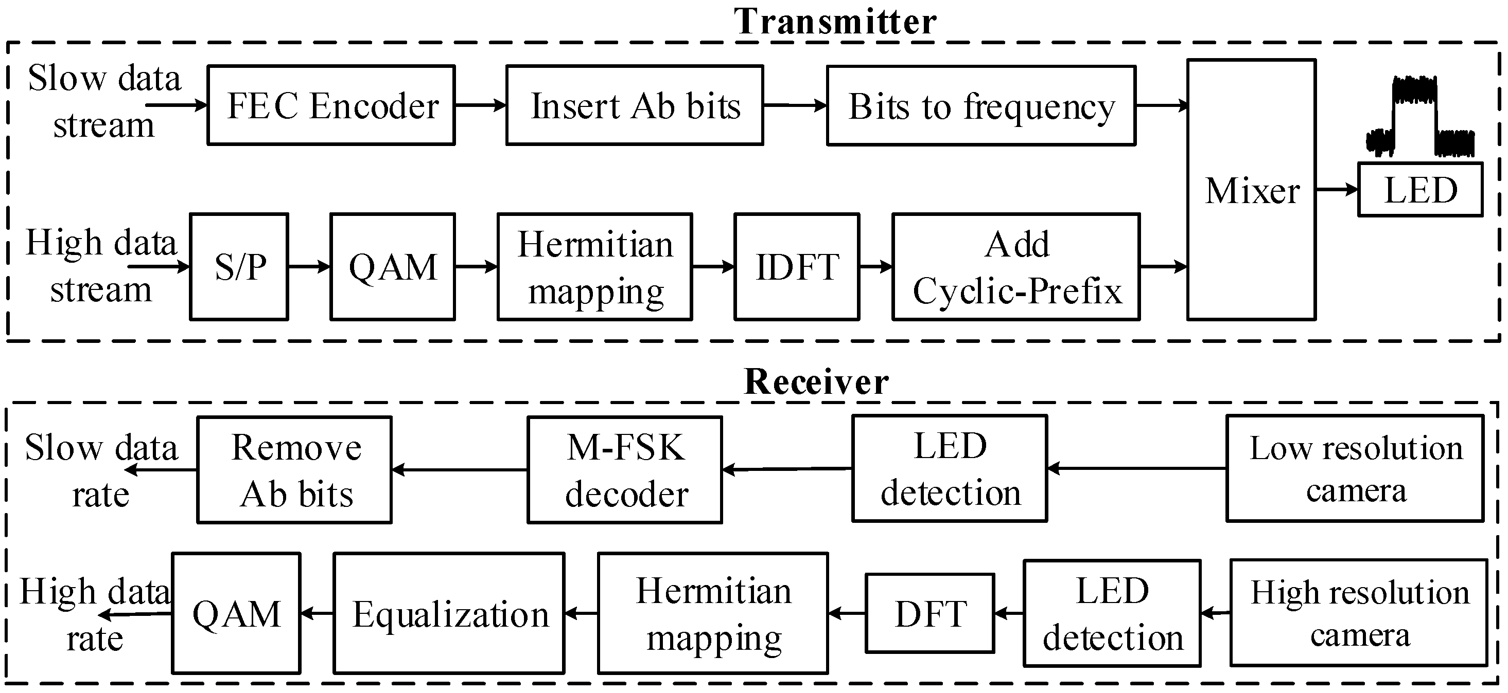
- The complete hybrid OFDM–FSK symbols at the Tx are as follows: new physical protocol data unit format for the hybrid scheme and design of the pilots and channel equalization for RS-OFDM scheme.
2. System Architecture
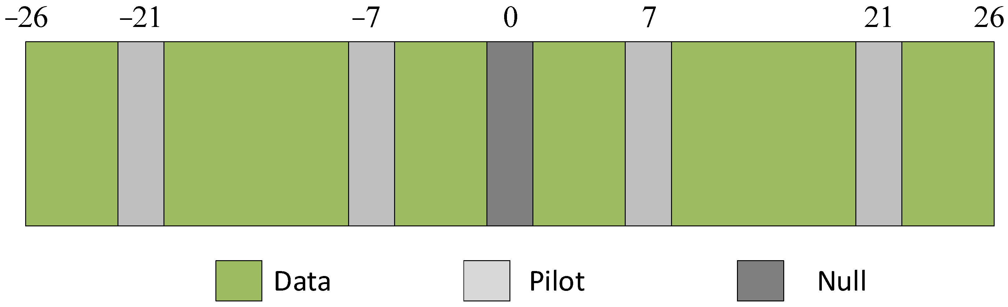
2.1. OFDM Scheme
2.2. M-FSK Operation
2.3. Hybrid OCC Scheme
- -
- Pilot
- -
- Channel Equalization
- -
- Rolling-Shutter OFDM Packet
- -
- M-FSK Packet
- -
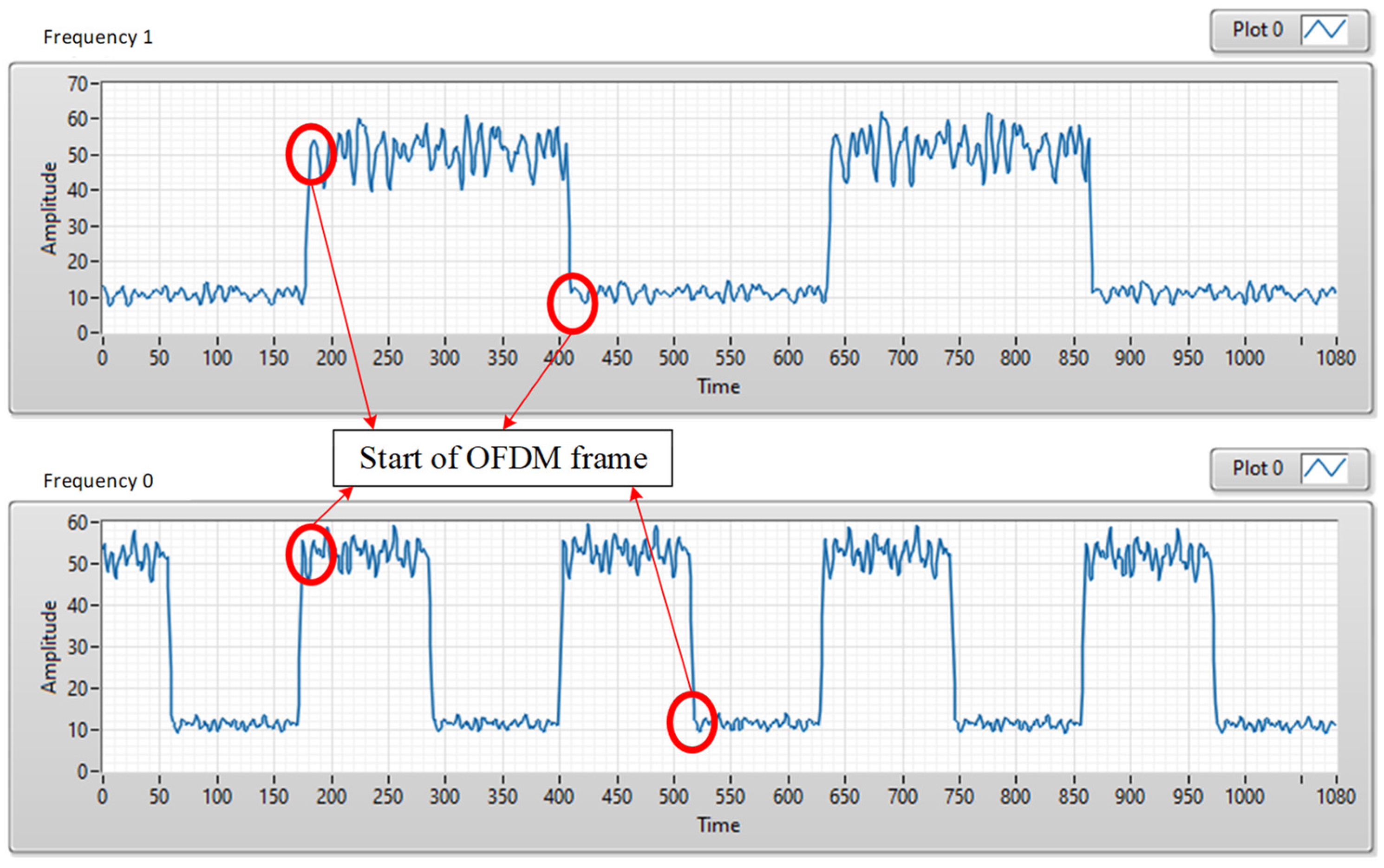
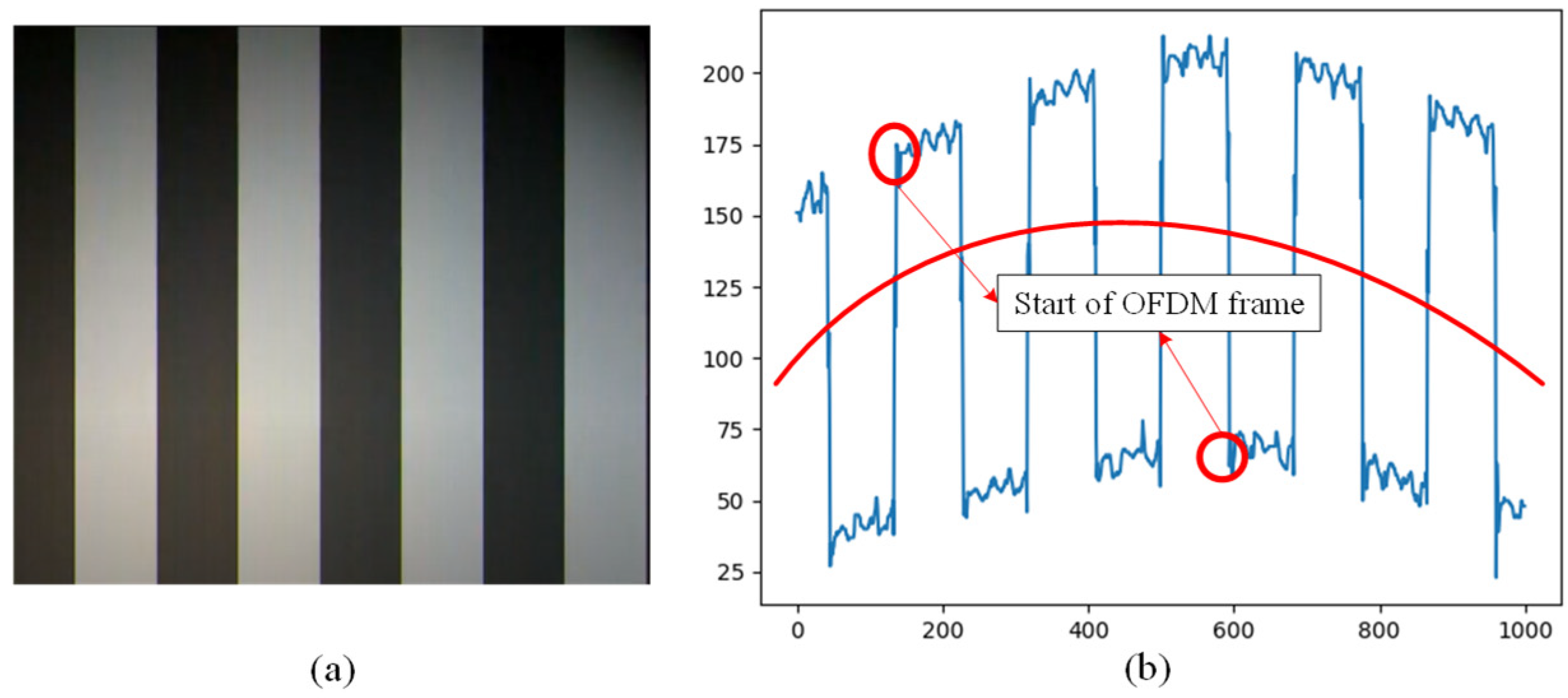
- OFDM Symbol Synchronization
- -
- Hybrid Waveforms
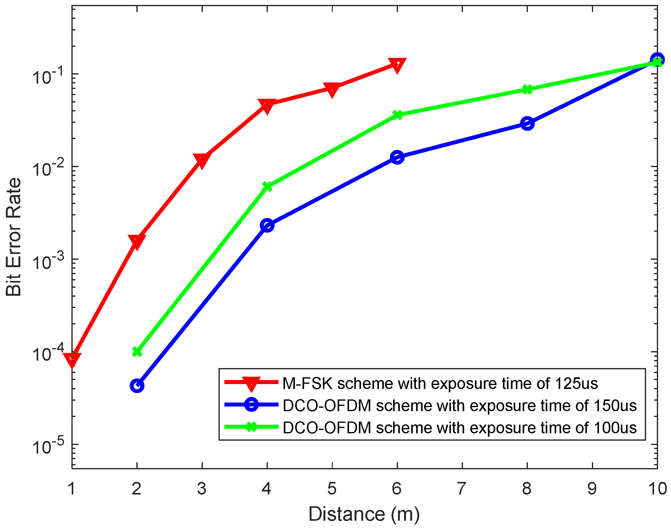
3. Implementation Results
4. Conclusions
Supplementary Materials
Author Contributions
Funding
Institutional Review Board Statement
Informed Consent Statement
Data Availability Statement
Conflicts of Interest
References
- Tan, K.-S.; Hinberg, I.; Wadhwani, J. Electromagnetic interference in medical devices: Health Canada’s past and current perspectives and activities. In Proceedings of the 2001 IEEE EMC International Symposium, Symposium Record, International Symposium on Electromagnetic Compatibility (Cat. No.01CH37161), Montreal, QC, Canada, 13–17 August 2001; Volume 2, pp. 1283–1288. [Google Scholar]
- Roberts-Intel, R.D.; Kyu, S. IEEE 802.15.7 visible light communication: Modulation and dimming support. IEEE Commun. Mag. 2012, 50, 72–82. [Google Scholar]
- An Overview on High-Speed Optical Wireless/Light Communications. Available online: https://mentor.ieee.org/802.11/dcn/17/11-17-0962-02-00lc-an-overview-on-high-speed-optical-wireless-light-communications.pdf (accessed on 27 October 2023).
- 802.15.7-2011; IEEE Standard for Local and Metropolitan Area Networks—Part 15.7: Short-Range Wireless Optical Communication Using Visible Light. IEEE Standard: Piscataway, NJ, USA, 2011.
- 802.15.7-2018; IEEE Standard for Local and Metropolitan Area Networks—Part 15.7: Short-Range Wireless Optical Communication. IEEE Standard: Piscataway, NJ, USA, 2018.
- Cahyadi, W.A.; Chung, Y.H.; Ghassemlooy, Z.; Hassan, N.B. Optical camera communications: Principles, modulations, potential and challenges. Electronics 2020, 9, 1339. [Google Scholar] [CrossRef]
- Pham, T.L.; Nguyen, T.; Thieu, M.D.; Nguyen, H.; Nguyen, H.; Jang, Y.M. An Artificial Intelligence-based Error Correction for Optical Camera Communication. In Proceedings of the 2019 Eleventh International Conference on Ubiquitous and Future Networks (ICUFN), Zagreb, Croatia, 2–5 July 2019; pp. 137–140. [Google Scholar]
- Huang, R.; Yamazato, T. A Review on Image Sensor Communication and Its Applications to Vehicles. Photonics 2023, 10, 617. [Google Scholar] [CrossRef]
- Grand View Research. Smart Transportation Market Size, Share & Trends Analysis Report By Solution (Ticketing Management System, Parking Management System, Integrated Supervision System), by Service, by Region, and Segment Forecasts, 2023–2030. 2023. Available online: https://www.grandviewresearch.com/industry-analysis/smart-transportation-market (accessed on 20 December 2023).
- Celik, A.; Romdhane, I.; Kaddoum, G.; Eltawil, A.M. A Top-Down Survey on Optical Wireless Communications for the Internet of Things. IEEE Commun. Surv. Tutor. 2022, 25, 1–45. [Google Scholar] [CrossRef]
- Aguiar-Castillo, L.; Guerra, V.; Rufo, J.; Rabadan, J.; Perez-Jimenez, R. Survey on Optical Wireless Communications-Based Services Applied to the Tourism Industry: Potentials and Challenges. Sensors 2021, 21, 6282. [Google Scholar] [CrossRef]
- Chang, Y.H.; Tsai, S.Y.; Chow, C.W.; Wang, C.C.; Tsai, D.C.; Liu, Y.; Yeh, C.H. Unmanned-aerial-vehicle based optical camera communication system using light-diffusing fiber and rolling-shutter image-sensor. Opt. Express 2023, 31, 18670–18679. [Google Scholar] [CrossRef]
- Teli, S.; Cahyadi, W.A.; Chung, Y.H. High-speed optical camera V2V communications using selective capture. Photonic Netw. Commun. 2018, 36, 210–216. [Google Scholar] [CrossRef]
- Feng, M.; Wang, Y.; Li, M.; Liu, S.; Huang, G.; Li, P. Design of OCC Indoor Positioning System Based on Flat Panel Light and Angle Sensor Assistance. Appl. Sci. 2023, 13, 4745. [Google Scholar] [CrossRef]
- White, I.; Curry, E.; Borah, D.K.; Stochaj, S.J.; Tang, W. An optical spatial localization algorithm using single temporal difference image sensor. IEEE Sens. Lett. 2019, 3, 1–4. [Google Scholar] [CrossRef]
- Van Hoa, N.; Nguyen, H.; Nguyen, C.H.; Jang, Y.M. OCC Technology-based Developing IoT Network. In Proceedings of the 2020 International Conference on Information and Communication Technology Convergence (ICTC), Jeju, Republic of Korea, 21–23 October 2020. [Google Scholar]
- Teli, S.R.; Guerra-Yanez, C.; Icaza, V.M.; Perez-Jimenez, R.; Ghassemlooy, Z.; Zvanovec, S. Hybrid Optical Wireless Communication for Versatile IoT Applications: Data Rate Improvement and Analysis. IEEE Access 2023, 11, 55107–55116. [Google Scholar] [CrossRef]
- Teli, S.R.; Chvojka, P.; Vítek, S.; Zvanovec, S.; Perez-Jimenez, R.; Ghassemlooy, Z. A SIMO hybrid visible-light communication system for optical IoT. IEEE Internet Things J. 2022, 9, 3548–3558. [Google Scholar] [CrossRef]
- Nguyen, T.; Thieu, M.D.; Jang, Y.M. 2D-OFDM for optical camera communication: Principle and implementation. IEEE Access 2019, 7, 29405–29424. [Google Scholar] [CrossRef]
- Nguyen, H.; Nguyen, V.L.; Tran, D.H.; Jang, Y.M. Rolling Shutter OFDM Scheme for Optical Camera Communication Consid-ering Mobility Environment Based on Deep Learning. Appl. Sci. 2022, 12, 8269. [Google Scholar] [CrossRef]
- Nguyen, D.T.; Park, S.; Chae, Y.; Park, Y. VLC/OCC hybrid optical wireless systems for versatile indoor applications. IEEE Access 2019, 7, 22371–22376. [Google Scholar] [CrossRef]
- Yang, F.; Gao, J.; Liu, S. Novel visible light communication approach based on hybrid OOK and ACO-OFDM. IEEE Photonics Technol. Lett. 2016, 28, 1585–1588. [Google Scholar] [CrossRef]
- Xu, C.; Xiang, L.; An, J.; Dong, C.; Sugiura, S.; Maunder, R.G.; Yang, L.L.; Hanzo, L. OTFS-Aided RIS-Assisted SAGIN Systems Outperform Their OFDM Counterparts in Doubly Selective High-Doppler Scenarios. IEEE Internet Things J. 2023, 10, 682–703. [Google Scholar] [CrossRef]
- Abdulwali, J.; Boussakta, S. Visible Light Communication: An Investigation of LED Non-Linearity Effects on VLC Utilising C-OFDM. Photonics 2022, 9, 192. [Google Scholar] [CrossRef]
- Armstrong, J.; Schmidt, B.J.C. Comparison of Asymmetrically Clipped Optical OFDM and DC-Biased Optical OFDM in AWGN. IEEE Commun. Lett. 2008, 12, 343–345. [Google Scholar] [CrossRef]
- Hosseini, H.; Fisal, N.; Syed-Yusof, S.K. Wavelet packet-based multicarrier modulation for cognitive UWB systems. Signal Process. Int. J. 2010, 4, 75–84. [Google Scholar]
- Huang, W.; Gong, C.; Xu, Z. System and waveform design for wavelet packet division multiplexing-based visible light communications. J. Light. Technol. 2015, 33, 3041–3051. [Google Scholar] [CrossRef]
- Rahman, M.H.; Sejan, M.A.S.; Chung, W.Y. Long-Distance Real-Time Rolling Shutter Optical Camera Communication Using MFSK Modulation Technique. In Proceedings of the International Conference on Intelligent Human Computer Interaction, Daegu, Republic of Korea, 24–26 November 2020; pp. 53–62. [Google Scholar]
- Hanzo, L.; Munster, M.; Choi, B.J.; Keller, T. OFDM and MC-CDMA for Broadband Multi-User Communications WLANs and Broadcasting, 1st ed.; John Wiley & Sons: Hoboken, NJ, USA, 2003. [Google Scholar]
- Dong, X.; Lu, W.; Soong, A.C.K. Linear interpolation in pilot symbol assisted channel estimation for OFDM. IEEE Trans. Wirel. Commun. 2007, 6, 1910–1920. [Google Scholar] [CrossRef]
- Van de Beek, J.; Sandell, M.; Borjesson, P.O. ML estimation of time and frequency offset in OFDM systems. IEEE Trans. Signal Process. 1997, 45, 1800–1805. [Google Scholar] [CrossRef]
- An, J.; Gan, L.; Liao, H. A non-data-aided algorithm based on ML for OFDM synchronization. In Proceedings of the 2018 International Conference on Electronics Technology (ICET), Chengdu, China, 23–27 May 2018; pp. 1–6. [Google Scholar]


| A Packet of Bits Input | Frequency Output |
|---|---|
| Preamble 1 | |
| 00 | |
| 01 | |
| 10 | |
| 11 | |
| Preamble 2 (Ab bit frequency) |
| Tx Side | ||
|---|---|---|
| Optical clock rate | 19.448 kHz | 43.413 kHz |
| OFDM symbol length | 64 | 128 |
| FEC | RS (15, 11) | |
| Packet rate | 20 packet/s | |
| LED type | 12 V, 2.5 W | |
| Rx Side | ||
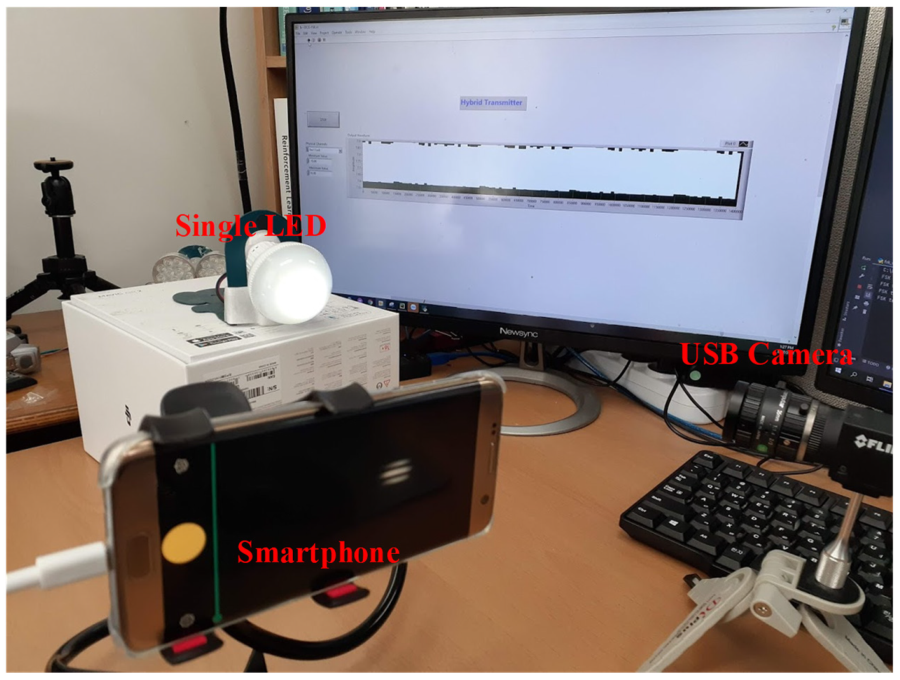
| Camera type | PointGrey rolling-shutter camera | |
| Camera frame rate | 60 fps | |
| Throughput | 2.560 kbps | 5.120 kbps |
| Camera type | Smartphone camera (Samsung S7 Edge) | |
| Camera frame rate | 240 fps | |
| Throughput | 40 bps | 80 bps |
Disclaimer/Publisher’s Note: The statements, opinions and data contained in all publications are solely those of the individual author(s) and contributor(s) and not of MDPI and/or the editor(s). MDPI and/or the editor(s) disclaim responsibility for any injury to people or property resulting from any ideas, methods, instructions or products referred to in the content. |
© 2024 by the authors. Licensee MDPI, Basel, Switzerland. This article is an open access article distributed under the terms and conditions of the Creative Commons Attribution (CC BY) license (https://creativecommons.org/licenses/by/4.0/).
Share and Cite
Nguyen, H.; Le, N.T.; Le, D.T.A.; Jang, Y.M. Design and Implementation of a Hybrid Optical Camera Communication System for Indoor Applications. Sensors 2024, 24, 300. https://doi.org/10.3390/s24010300
Nguyen H, Le NT, Le DTA, Jang YM. Design and Implementation of a Hybrid Optical Camera Communication System for Indoor Applications. Sensors. 2024; 24(1):300. https://doi.org/10.3390/s24010300
Chicago/Turabian StyleNguyen, Huy, Nam Tuan Le, Duy Tuan Anh Le, and Yeong Min Jang. 2024. "Design and Implementation of a Hybrid Optical Camera Communication System for Indoor Applications" Sensors 24, no. 1: 300. https://doi.org/10.3390/s24010300
APA StyleNguyen, H., Le, N. T., Le, D. T. A., & Jang, Y. M. (2024). Design and Implementation of a Hybrid Optical Camera Communication System for Indoor Applications. Sensors, 24(1), 300. https://doi.org/10.3390/s24010300