
Design, Analysis, and Development of Low-Cost State-of-the-Art Magnetorheological-Based Microprocessor Prosthetic Knee

 , and
, and
Abstract
1. Introduction
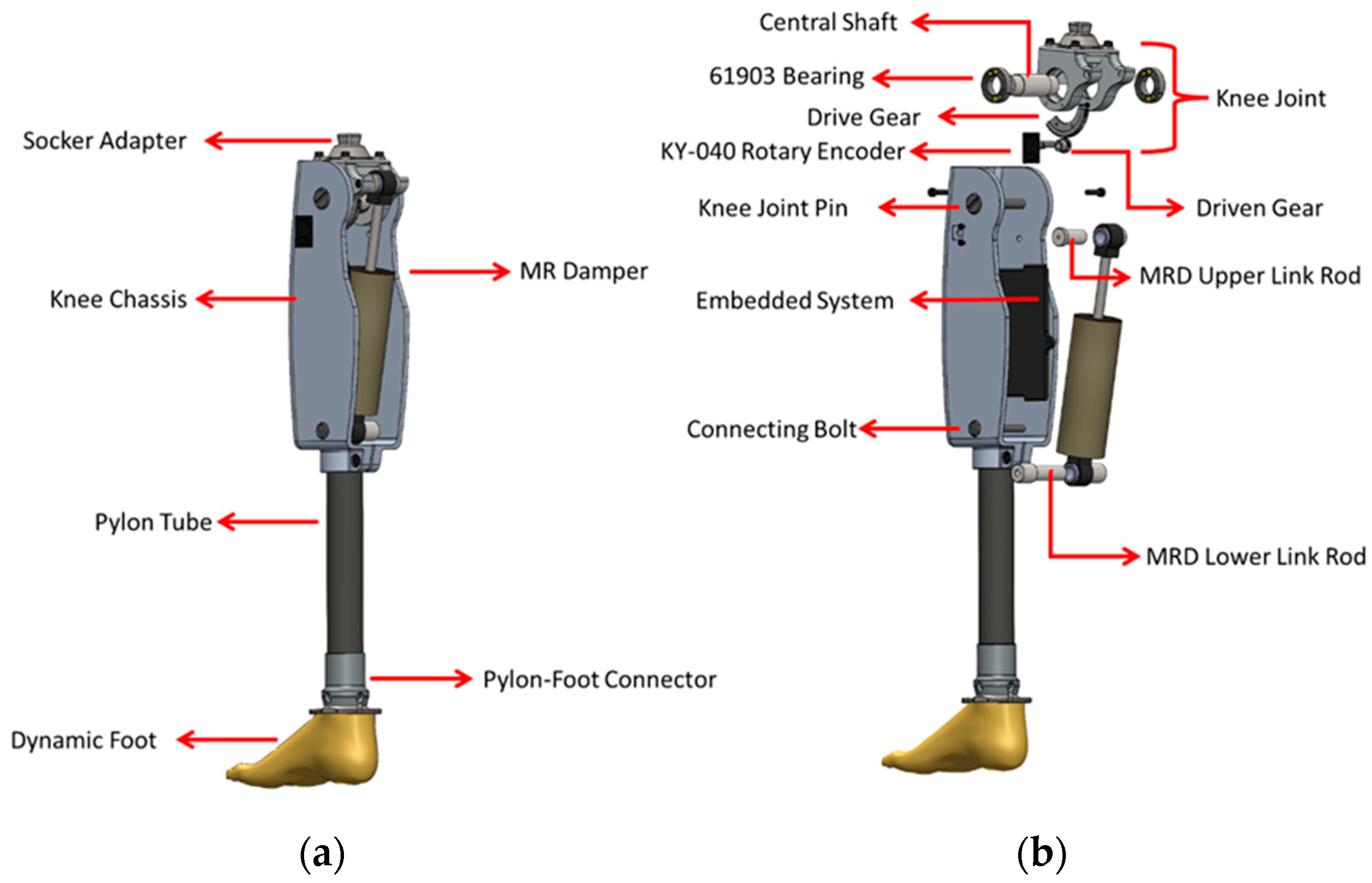
2. Mechanical Design
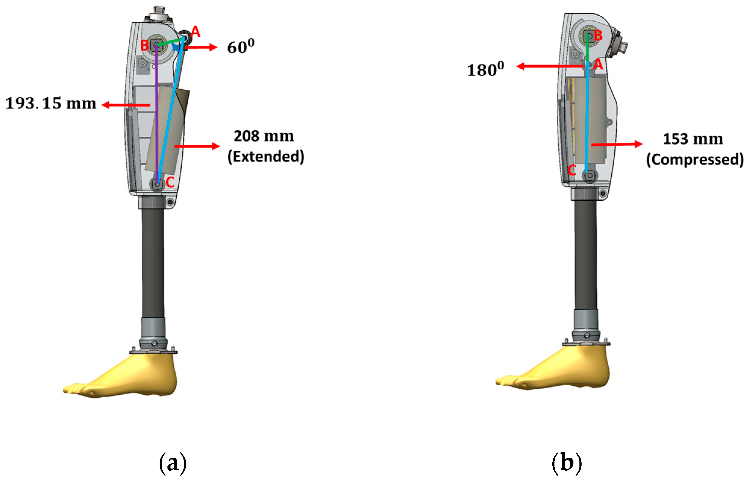
- AB is the length from the knee joint axis to the upper busing axis of the MR damper;
- AC is the extended/retracted length of the MR damper;
- BC is the length from the knee joint axis to the lower bushing axis of the MR damper.
3. Structural Analysis of i-Inspire Knee
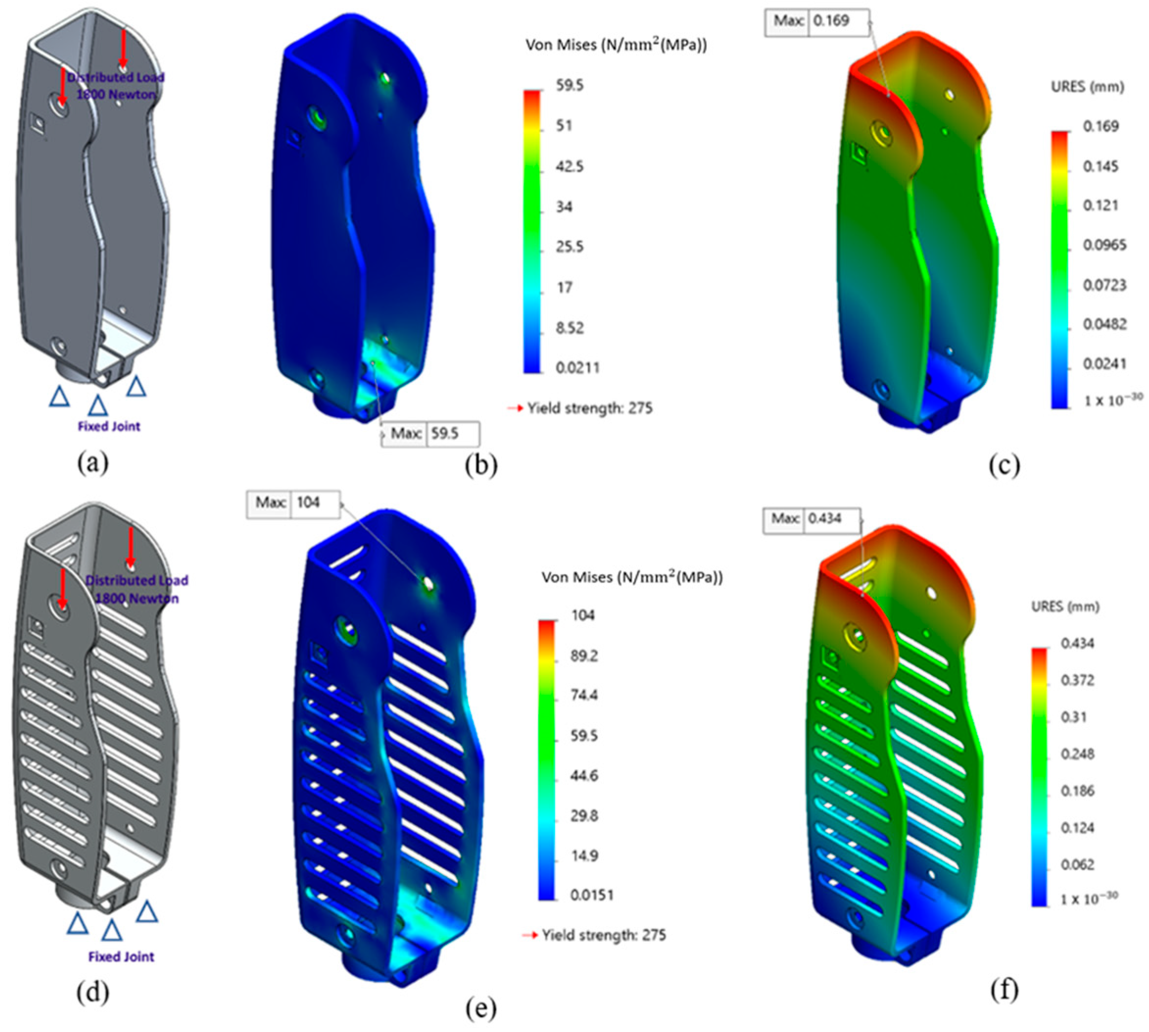
3.1. Boundary Conditions
3.2. Von Mises Stress and Total Deformation
3.3. Results
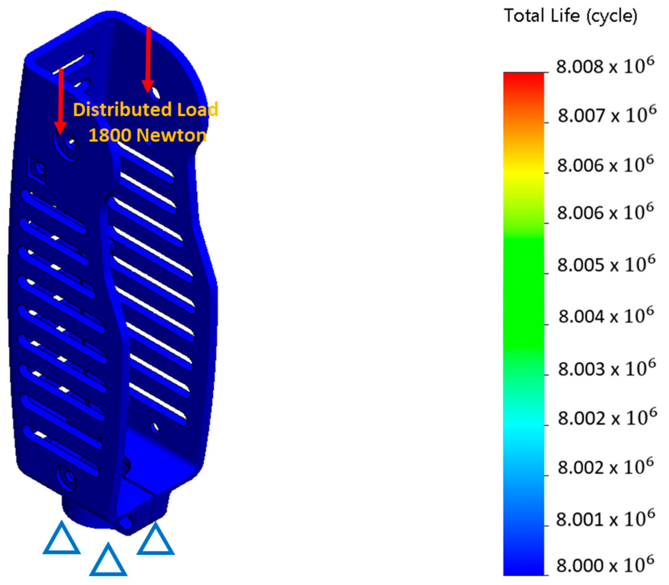
3.4. Fatigue Analysis
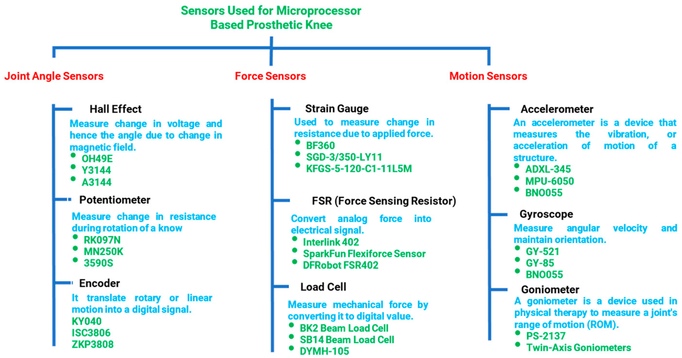
4. Sensing System for i-Inspire Knee
- Angle sensor measures the inclination/angle of the knee joint and estimates the amputee’s walking speed.
- Force sensing is necessary for differentiating between the stance and swing phases of the gait cycle.
- Motion sensing assists in the reconstruction of the position of the prosthesis in 3D space for accurate intent recognition.
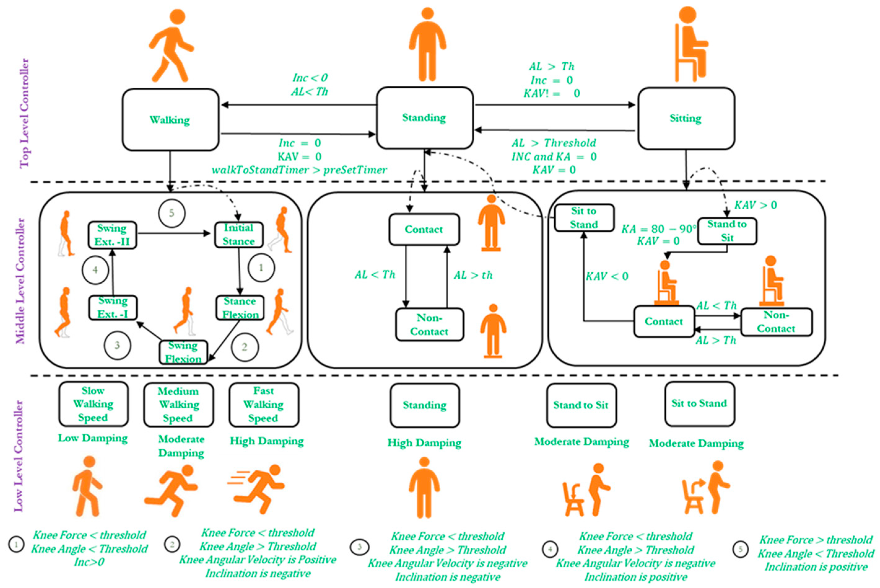
5. Control Architecture of i-Inspire Knee
- A positive slope (inclination angle) indicates the knee joint’s forward inclination.
- A negative slope (inclination angle) indicates the knee joint’s backward inclination.
- Zero slope (within ±3° of uncertainty) represents that the knee joint is perpendicular to the ground (as in the case of standing position)
- During flexion, with reference to the knee chassis, anti-clock wise rotation of the knee joint is observed, resulting in a positive angular velocity.
- During extension, with reference to the knee chassis, clocl-wise rotation of the knee joint is observed, resulting in a positive angular velocity.
5.1. Top-Level Controller
5.2. Middle-Level Controller
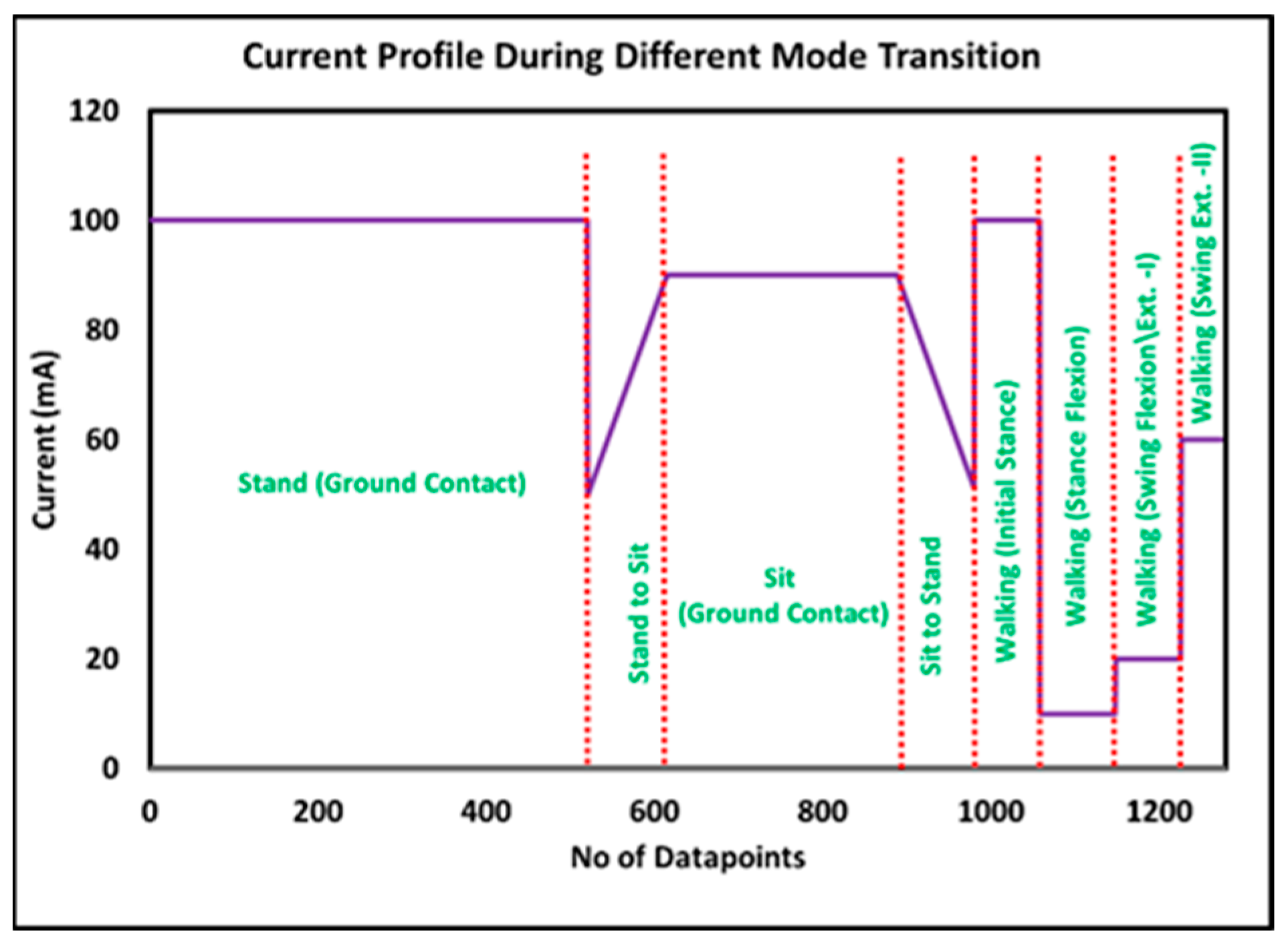
5.2.1. Middle-Level Controller for Standing Mode
5.2.2. Middle-Level Controller for Sitting Mode
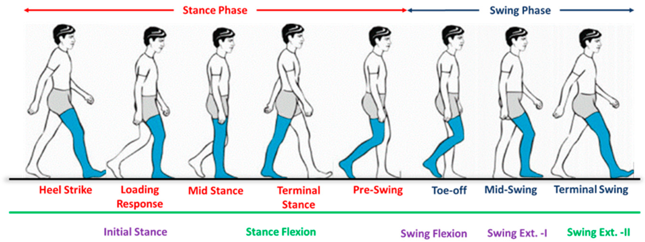
5.2.3. Middle-Level Controller for Walking Mode
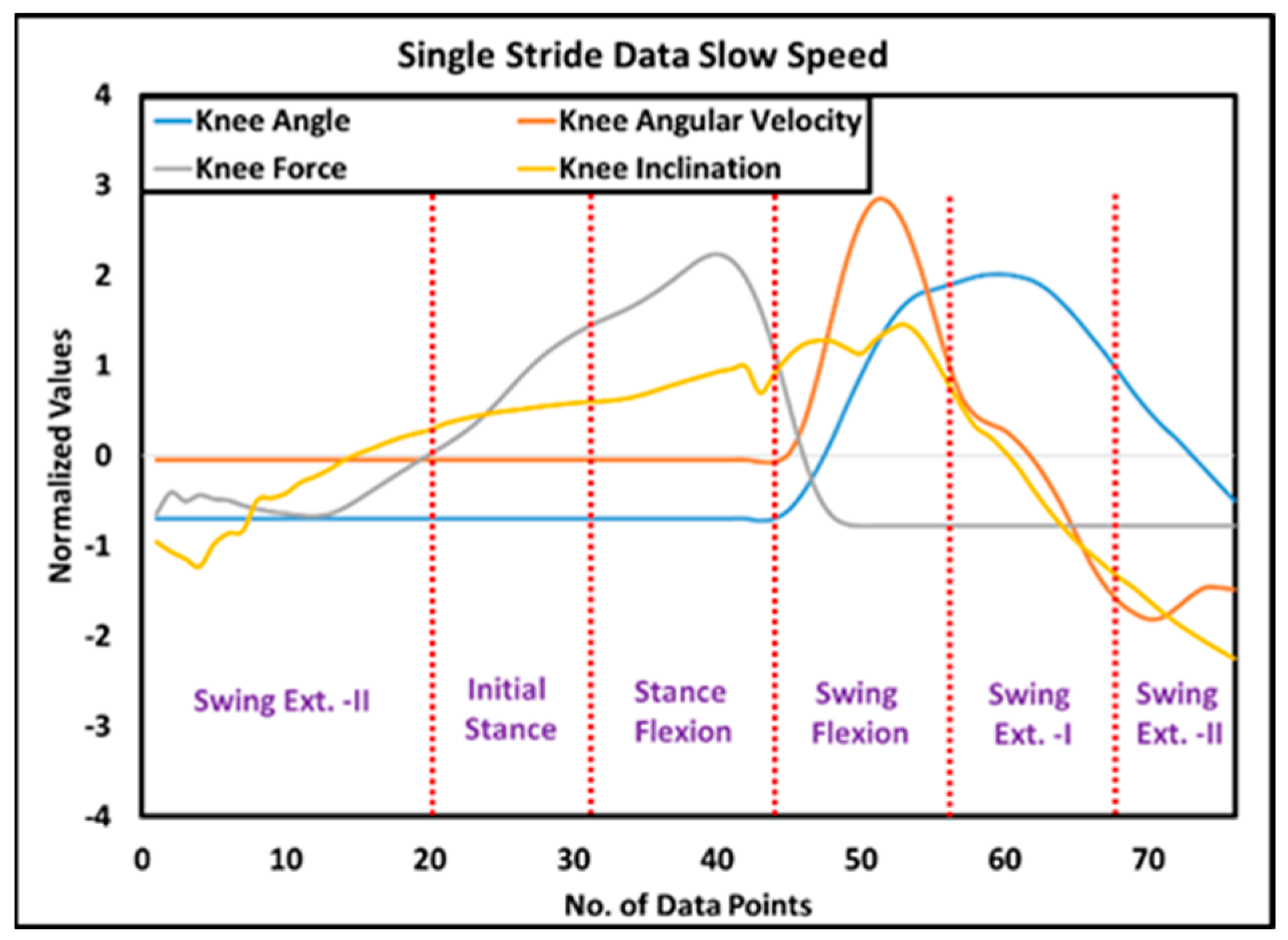
- Initial stance: The initial stance is observed at the heel strike when the knee joint is inclined forward, and the prosthesis starts to bear the amputee load. Therefore, there is a positive inclination angle, knee loading less than the threshold, and a knee angle less than the preset threshold result in the detection of loading response. In this study, the initial stance was extended until the mid-stance phase, when it is assumed that the knee joint remains fully extended.
- Stance flexion: The knee joint flexes from mid-stance to pre-swing, resulting in a backward (negative) chassis inclination while the prosthesis still supports the body weight. Therefore, when the controller detects a negative inclination angle, knee loading greater than the threshold, and positive angular velocity, it activates the stance flexion phase of the gait cycle.
- Swing flexion: After the toe-off, the stance phase is completed, and the swing phase is initiated; hence, the prosthesis does not support body weight. However, the knee joint flexes until the maximum flexion angle (MFA) is achieved. Consequently, a negative knee inclination, knee loading less than the threshold, and positive angular velocity mark the beginning of swing flexion.
- Swing extension: Immediately after the attainment of the maximum flexion angle, the knee joint extends until the next heel strike. The swing extension can be identified when the knee loading is less than the threshold, and the angular velocity of the knee joint is negative. As discussed earlier, the swing extension is subdivided into two sub-phases, i.e., swing extension (I) and swing extension (II). Swing extension (I) begins after MFA. It lasts until mid-swing, during which the inclination of the prosthesis is negative, whereas, from mid-swing to the next heel strike, a positive inclination of the prosthesis is recorded, and, hence, the controller switches to swing extension (II).
5.3. Low-Level Controller
5.3.1. Low-Level Controller for Standing
5.3.2. Low-Level Controller for Sitting
5.3.3. Low-Level Controller for Walking
6. Evaluation
7. Results
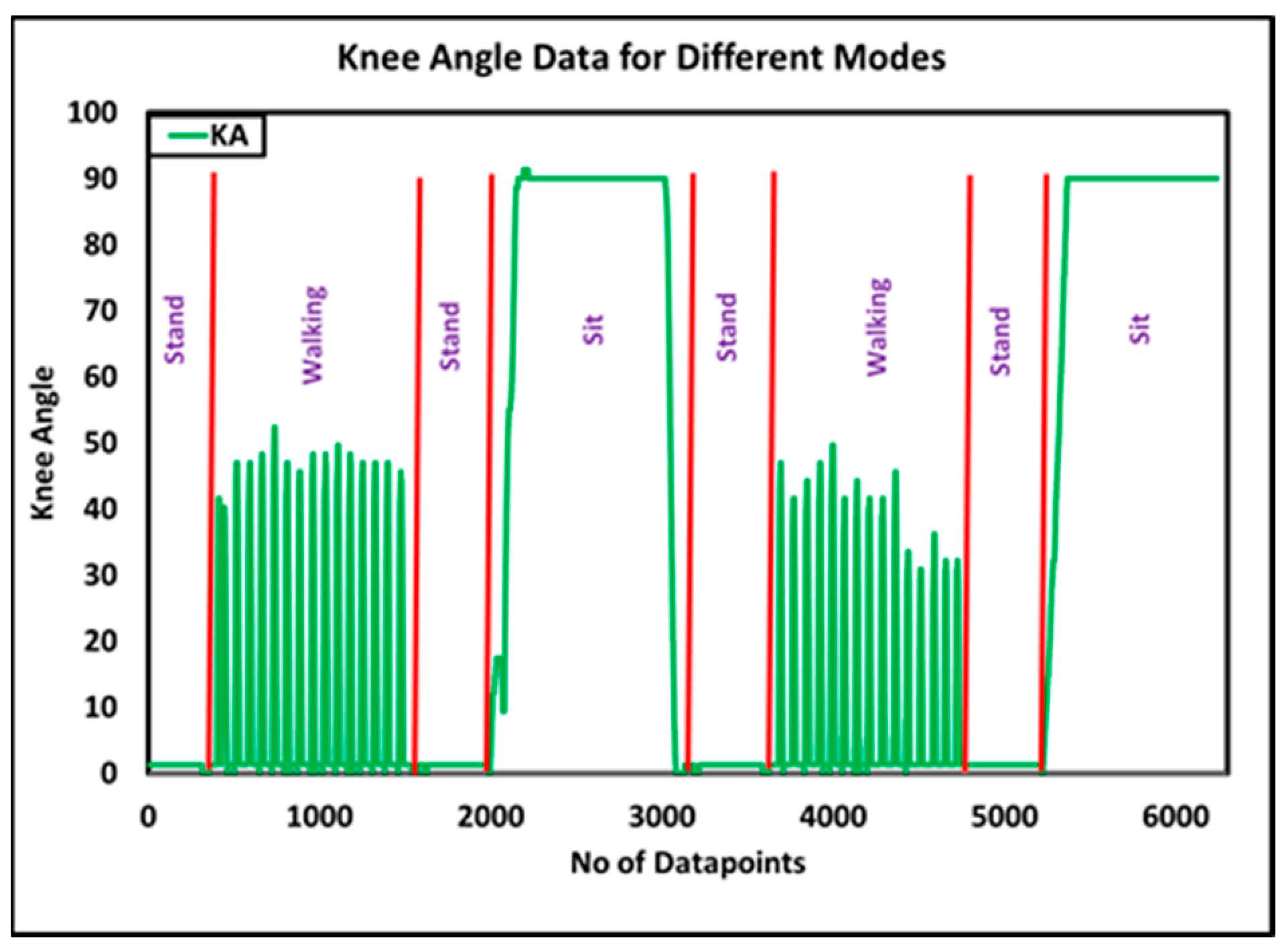
7.1. Evaluation of Top-Level Controller
7.2. Evaluation of Middle-Level Walking Controller
7.3. Evaluation of Low-Level Current Controller
7.4. Evaluation of Speed-Adaptive Control Algorithm
7.5. Comparison with State-of-the-Art Commercial Prosthesis
8. Conclusions
Author Contributions
Funding
Institutional Review Board Statement
Informed Consent Statement
Data Availability Statement
Conflicts of Interest
References
- Sahu, A.; Sagar, R.; Sarkar, S.; Sagar, S. Psychological effects of amputation: A review of studies from India. Ind. Psychiatry J. 2016, 25, 4. [Google Scholar] [PubMed]
- Hassan Al Imam, M.; Alamgir, H.; Jahan Akhtar, N.; Hossain, Z.; Islam, R.; Sohrab Hossain, M. Characterisation of persons with lower limb amputation who attended a tertiary rehabilitation centre in Bangladesh. Disabil. Rehabil. 2020, 42, 1995–2001. [Google Scholar] [CrossRef] [PubMed]
- McDonald, C.L.; Westcott-McCoy, S.; Weaver, M.R.; Haagsma, J.; Kartin, D. Global prevalence of traumatic non-fatal limb amputation. Prosthet. Orthot. Int. 2021, 45, 0309364620972258. [Google Scholar] [CrossRef] [PubMed]
- Qadir, M.U.; Khan, M.A.; Hussain, M.; ul Haq, I.; Akhtar, N.; Shah, K. Design and Analysis of Knee Joint for Transfemoral Amputees. In Proceedings of the 2021 International Conference on Artificial Intelligence and Mechatronics Systems (AIMS), Bandung, Indonesia, 28–30 April 2021; pp. 1–5. [Google Scholar]
- Seymour, R.; Engbretson, B.; Kott, K.; Ordway, N.; Brooks, G.; Crannell, J.; Hickernell, E.; Wheeler, K. Comparison between the C-leg® microprocessor-controlled prosthetic knee and non-microprocessor control prosthetic knees: A preliminary study of energy expenditure, obstacle course performance, and quality of life survey. Prosthet. Orthot. Int. 2007, 31, 51–61. [Google Scholar] [CrossRef]
- Jaegers, S.M.; Vos, L.D.; Rispens, P.; Hof, A.L. The relationship between comfortable and most metabolically efficient walking speed in persons with unilateral above-knee amputation. Arch. Phys. Med. Rehabil. 1993, 74, 521–525. [Google Scholar] [CrossRef]
- Martin, J.; Pollock, A.; Hettinger, J.J. Microprocessor lower limb prosthetics: Review of current state of the art. J. Prosthet. Orthot. 2010, 22, 183–193. [Google Scholar] [CrossRef]
- Rigelsford, J. Control of movement for the physically disabled. Ind. Robot. Int. J. 2001, 28. [Google Scholar] [CrossRef]
- Berke, G.M.; Geil, M. Appendix microprocessor knee manufacturers forum report. JPO J. Prosthet. Orthot. 2013, 25, P80–P83. [Google Scholar] [CrossRef]
- Highsmith, M.J.; Kahle, J.T.; Wernke, M.M.; Carey, S.L.; Miro, R.M.; Lura, D.J.; Sutton, B.S. Effects of the Genium knee system on functional level, stair ambulation, perceptive and economic outcomes in transfemoral amputees. Technol. Innov. 2016, 18, 139–150. [Google Scholar] [CrossRef]
- Herr, H.; Wilkenfeld, A. User-adaptive control of a magnetorheological prosthetic knee. Ind. Robot. Int. J. 2003, 30, 42–55. [Google Scholar] [CrossRef]
- Ekkachai, K.; Nilkhamhang, I. Swing phase control of semi-active prosthetic knee using neural network predictive control with particle swarm optimization. IEEE Trans. Neural Syst. Rehabil. Eng. 2016, 24, 1169–1178. [Google Scholar] [CrossRef] [PubMed]
- Pieringer, D.S.; Grimmer, M.; Russold, M.F.; Riener, R. Review of the actuators of active knee prostheses and their target design outputs for activities of daily living. In Proceedings of the 2017 International Conference on Rehabilitation Robotics (ICORR), London, UK, 17–20 July 2017; pp. 1246–1253. [Google Scholar]
- Varol, H.A.; Sup, F.; Goldfarb, M. Multiclass real-time intent recognition of a powered lower limb prosthesis. IEEE Trans. Biomed. Eng. 2009, 57, 542–551. [Google Scholar] [CrossRef] [PubMed]
- Ambrozic, L.; Gorsic, M.; Geeroms, J.; Flynn, L.; Lova, R.M.; Kamnik, R.; Munih, M.; Vitiello, N. CYBERLEGs: A user-oriented robotic transfemoral prosthesis with whole-body awareness control. IEEE Robot. Autom. Mag. 2014, 21, 82–93. [Google Scholar] [CrossRef]
- Canino, J.M.; Fite, K.B. Haptic feedback in lower-limb prosthesis: Combined haptic feedback and EMG control of a powered prosthesis. In Proceedings of the 2016 IEEE EMBS International Student Conference (ISC), Ottawa, ON, Canada, 29–31 May 2016; pp. 1–4. [Google Scholar]
- Zhang, F.; Liu, M.; Huang, H. Preliminary study of the effect of user intent recognition errors on volitional control of powered lower limb prostheses. In Proceedings of the 2012 Annual International Conference of the IEEE Engineering in Medicine and Biology Society, San Diego, CA, USA, 28 August–1 September 2012; pp. 2768–2771. [Google Scholar]
- Power Knee. A New Era in Motion. 2022. Available online: https://www.ossur.com/en-us/prosthetics/explore-power-knee (accessed on 15 November 2023).
- Ochoa-Diaz, C.; Rocha, T.S.; de Levy Oliveira, L.; Paredes, M.G.; Lima, R.; Bó, A.P.L.; Borges, G.A. An above-knee prosthesis with magnetorheological variable-damping. In Proceedings of the 5th IEEE RAS/EMBS International Conference on Biomedical Robotics and Biomechatronics, Sao Paulo, Brazil, 12–15 August 2014; pp. 108–113. [Google Scholar]
- Safaeepour, Z.; Eshraghi, A.; Geil, M.J.P.; International, O. The effect of damping in prosthetic ankle and knee joints on the biomechanical outcomes: A literature review. Prosthet. Orthot. Int. 2017, 41, 336–344. [Google Scholar] [CrossRef] [PubMed]
- Cao, W.; Yu, H.; Chen, W.; Meng, Q.; Chen, C.J.I.A. Design and evaluation of a novel microprocessor-controlled prosthetic knee. IEEE Access 2019, 7, 178553–178562. [Google Scholar] [CrossRef]
- Seid, S.; Sujatha, S.; Chandramohan, S. Design and evaluation of swing phase controllers for single-axis knee. Int. J. Bioautomation 2016, 20, 373–388. [Google Scholar]
- Cao, W.; Yu, H.; Zhao, W.; Meng, Q.; Chen, W.J.T.; Care, H. The comparison of transfemoral amputees using mechanical and microprocessor-controlled prosthetic knee under different walking speeds: A randomized cross-over trial. Technol. Health Care 2018, 26, 581–592. [Google Scholar] [CrossRef]
- Ulasyar, A.; Lazoglu, I. Design and analysis of a new magneto rheological damper for washing machine. J. Mech. Sci. Technol. 2018, 32, 1549–1561. [Google Scholar] [CrossRef]
- Rahman, M.; Ong, Z.C.; Julai, S.; Ferdaus, M.M.; Ahamed, R. A review of advances in magnetorheological dampers: Their design optimization and applications. J. Zhejiang Univ. Sci. A 2017, 18, 991–1010. [Google Scholar] [CrossRef]
- Fu, Q.; Wang, D.-H.; Xu, L.; Yuan, G. A magnetorheological damper-based prosthetic knee (MRPK) and sliding mode tracking control method for an MRPK-based lower limb prosthesis. Smart Mater. Struct. 2017, 26, 045030. [Google Scholar] [CrossRef]
- Xu, L.; Wang, D.-H.; Fu, Q.; Yuan, G.; Hu, L.Z. A novel four-bar linkage prosthetic knee based on magnetorheological effect: Principle, structure, simulation and control. Smart Mater. Struct. 2016, 25, 115007. [Google Scholar] [CrossRef]
- Park, J.; Yoon, G.-H.; Kang, J.-W.; Choi, S.-B. Design and control of a prosthetic leg for above-knee amputees operated in semi-active and active modes. Smart Mater. Struct. 2016, 25, 085009. [Google Scholar] [CrossRef]
- Craig, J. Prosthetic Feet for Low-Income Countries. JPO J. Prosthet. Orthot. 2005, 17, S47–S49. [Google Scholar] [CrossRef]
- WHO. Disability and Health. 2016. Available online: http://www.who.int/mediacentre/factsheets/fs352/en/ (accessed on 15 November 2023).
- Walsh, N.E.; Walsh, W.S. Rehabilitation of landmine victims: The ultimate challenge. Bull. World Health Organ. 2003, 81, 665–670. [Google Scholar]
- Strait, E.N. Prosthetics in Developing Countries. Prosthet. Resid. 2006, 1, 1–3. [Google Scholar]
- Pandit, S.; Godiyal, A.K.; Vimal, A.K.; Singh, U.; Joshi, D.; Kalyanasundaram, D. An affordable insole-sensor-based trans-femoral prosthesis for normal gait. Sensors 2018, 18, 706. [Google Scholar] [CrossRef] [PubMed]
- Sharma, R.; Singh, D.; Tiwari, A.; Joshi, D. User-feedback based robust and simplified damping control for affordable transfemoral prosthesis. Electron. Lett. 2020, 56, 366–367. [Google Scholar] [CrossRef]
- Galey, L.; Gonzalez, R.V. Design and Initial Evaluation of a Low-Cost Microprocessor-Controlled Above-Knee Prosthesis: A Case Report of 2 Patients. Prosthesis 2022, 4, 60–72. [Google Scholar] [CrossRef]
- Grabowski, A.M.; D’Andrea, S. Effects of a powered ankle-foot prosthesis on kinetic loading of the unaffected leg during level-ground walking. J. Neuroeng. Rehabil. 2013, 10, 49. [Google Scholar] [CrossRef]
- ISO 10328:2016; Prosthetics—Structural Testing of Lower Limb Prostheses. ISO: Geneva, Switzerland, 2016.
- Singleton, S.J.; Keating, S.E.; McDowell, S.L.; Coolen, B.A.; Wall, J.C. Predicting step time from step length and velocity. Aust. J. Physiother. 1992, 38, 43–46. [Google Scholar] [CrossRef]
- Quintero, D.; Villarreal, D.J.; Lambert, D.J.; Kapp, S.; Gregg, R.D. Continuous-phase control of a powered knee–ankle prosthesis: Amputee experiments across speeds and inclines. IEEE Trans. Robot. 2018, 34, 686–701. [Google Scholar] [CrossRef] [PubMed]
- Heng, W.; Pang, G.; Xu, F.; Huang, X.; Pang, Z.; Yang, G.J.S. Flexible insole sensors with stably connected electrodes for gait phase detection. Sensors 2019, 19, 5197. [Google Scholar] [CrossRef] [PubMed]
- Aqueveque, P.; Germany, E.; Osorio, R.; Pastene, F.J.S. Gait segmentation method using a plantar pressure measurement system with custom-made capacitive sensors. Sensors 2020, 20, 656. [Google Scholar] [CrossRef] [PubMed]
- Zhang, Q.; Wang, Y.L.; Xia, Y.; Wu, X.; Kirk, T.V.; Chen, X.D. A low-cost and highly integrated sensing insole for plantar pressure measurement. Sens. Bio-Sens. Res. 2019, 26, 100298. [Google Scholar] [CrossRef]
- Prado, A.; Cao, X.; Ding, X.; Agrawal, S.K. Prediction of gait cycle percentage using instrumented shoes with artificial neural networks. In Proceedings of the 2020 IEEE International Conference on Robotics and Automation (ICRA), Paris, France, 31 May–31 August 2020; pp. 2834–2840. [Google Scholar]
- Min, H.G.; Jeung, E.T. Complementary Filter Design for Angle Estimation Using Mems Accelerometer and Gyroscope; Department of Control and Instrumentation, Changwon National University: Changwon, Republic of Korea, 2015; pp. 641–773. [Google Scholar]
- Mahmood, D.; Javaid, N.; Imran, M.; Qasim, U.; Khan, Z.A. Data Fusion for Orientation Sensing in Wireless Body Area Sensor Networks using Smart Phones. Sensors 2015, 15, 14458–14486. [Google Scholar]
- Price, C.; Schmeltzpfenning, T.; Nester, C.J.; Brauner, T. Foot and footwear biomechanics and gait. In Handbook of Footwear Design and Manufacture; Elsevier: Amsterdam, The Netherlands, 2021; pp. 79–103. [Google Scholar]
- Su, B.; Gutierrez-Farewik, E.M.J.S. Gait trajectory and gait phase prediction based on an LSTM network. Sensors 2020, 20, 7127. [Google Scholar] [CrossRef] [PubMed]
- Vu, H.T.T.; Dong, D.; Cao, H.-L.; Verstraten, T.; Lefeber, D.; Vanderborght, B.; Geeroms, J.J.S. A review of gait phase detection algorithms for lower limb prostheses. Sensors 2020, 20, 3972. [Google Scholar] [CrossRef] [PubMed]
- Attal, F.; Amirat, Y.; Chibani, A.; Mohammed, S. Automatic recognition of gait phases using a multiple-regression hidden Markov model. IEEE/ASME Trans. Mechatron. 2018, 23, 1597–1607. [Google Scholar] [CrossRef]
- Kaufman, K.R.; Frittoli, S.; Frigo, C.A. Gait asymmetry of transfemoral amputees using mechanical and microprocessor-controlled prosthetic knees. Clin. Biomech. 2012, 27, 460–465. [Google Scholar] [CrossRef]
- Segal, A.D.; Orendurff, M.S.; Klute, G.K.; McDowell, M.; Pecoraro, J.A.; Shofer, J.; Czerniecki, J.M. Kinematic and kinetic comparisons of transfemoral amputee gait using C-Leg® and Mauch SNS® prosthetic knees. J. Rehabil. Res. Dev. 2006, 43, 857. [Google Scholar] [CrossRef]
- Libre Texts Mathematics. Exponential Growth. Available online: https://math.libretexts.org/Bookshelves/Applied_Mathematics/Book%3A_College_Mathematics_for_Everyday_Life_(Inigo_et_al)/04%3A_Growth/4.02%3A_Exponential_Growth (accessed on 15 November 2023).
- Wilkenfeld, A.J. Biologically Inspired Autoadaptive Control of a Knee Prosthesis. Ph.D. Thesis, Massachusetts Institute of Technology, Cambridge, MA, USA, 2000. [Google Scholar]
- Moosabhoy, M.A.; Gard, S.A. Methodology for determining the sensitivity of swing leg toe clearance and leg length to swing leg joint angles during gait. Gait Posture 2006, 24, 493–501. [Google Scholar] [CrossRef] [PubMed]
- Liu, Z.; Lin, W.; Geng, Y.; Yang, P. Intent pattern recognition of lower-limb motion based on mechanical sensors. IEEE/CAA J. Autom. Sin. 2017, 4, 651–660. [Google Scholar] [CrossRef]
- Jamadar, M.-e.-H.; Desai, R.M.; Saini, R.S.T.; Kumar, H.; Joladarashi, S. Dynamic analysis of a quarter car model with semi-active seat suspension using a novel model for magneto-rheological (MR) damper. J. Vib. Eng. Technol. 2021, 9, 161–176. [Google Scholar] [CrossRef]
- Thiele, J.; Westebbe, B.; Bellmann, M.; Kraft, M. Designs and performance of microprocessor-controlled knee joints. Biomed. Tech. 2014, 59, 65–77. [Google Scholar] [CrossRef]
- Zahedi, S.; Sykes, A.; Lang, S.; Cullington, I.J.R. Adaptive prosthesis—A new concept in prosthetic knee control. Robotica 2005, 23, 337–344. [Google Scholar] [CrossRef]
- Palmer, M.L.; Bisbee, C.R., III. Computer controlled prosthetic knee device. U.S. Patent 7,655,050, 2 February 2010. [Google Scholar]
- Steele, W.; Quintero, H.; Van Wieren, P.; McFadden, M.P. Method and System for a Prosthetic Device with Multiple Levels of Functionality Enabled through Multiple Control Systems. U.S. Patent 20140172120A1, 19 June 2014. [Google Scholar]
- Herr, H.M.; Wilkenfeld, A.; Bleck, O. Speed-Adaptive and Patient-Adaptive Prosthetic Knee. U.S. Patent 6610101B2, 26 August 2007. [Google Scholar]
- Herr, H.M.; Wilkenfeld, A.; Bleck, O. Control System for Prosthetic Knee. U.S. Patent 7799091B2, 21 September 2010. [Google Scholar]
- Kampas, P.; Pawlik, R. Orthopedic device with a joint. U.S. Patent No. 9,913,739, 13 March 2018. [Google Scholar]
- Seifert, D. Method for Controlling a Change of Damping in an Artificial Joint. U.S. Patent 10772743B2, 15 September 2020. [Google Scholar]


| Sr. # | Feature | Specification |
|---|---|---|
| 1 | Weight-bearing capacity | Support patient weight up to 130 kg |
| 2 | Max. knee flexion angle | 120° |
| 3 | TP weight | 1200–1800 g |
| 4 | TP cost | Less than 1500 USD |
| 5 | Walking controller | FSM-based variable damping |
| 6 | Available modes | Walking, sitting, standing, knee locking |
| 7 | Self-selected walking speed | Control knee flexion at different walking speeds within a range of 55–65° |
| Parameter | Value |
|---|---|
| Stroke, mm (in) | 55 (2.17) |
| Extended length, mm (in) | 208 (8.2) |
| Body diameter, mm (in) | 42.1 (1.66) max |
| Shaft diameter, mm (in) | 10 (0.39) |
| Tensile strength, N (lbf) | 8896 (2000) max. |
| Damper forces, N (lbf) | |
| Peak to peak | |
| 5 cm/s @ 1 A | >2447 (>550) |
| 20 cm/s @ 0 A | <667 (<150) |
| Operating temperature, °C (°F) | 71 (160) max. |
| Sr. # | Parameter | Value |
|---|---|---|
| 1 | Height (m) | 1.75 |
| 2 | Weight (kg) | 95 |
| 3 | Age (years) | 38 |
| 4 | Amputation side | Right |
| 5 | Stump length (cm) | 30 |
| 6 | Prosthetic foot | Flex foot |
| 7 | Socket design | Quadrilateral |
| Sr. # | Statistical Analysis | Slow Knee Angle | Slow Knee Force | Slow Knee Inclination | Medium Knee Angle | Medium Knee Force | Medium Knee Inclination |
|---|---|---|---|---|---|---|---|
| 1 | Total strides | 26 | |||||
| 2 | Stable strides | 20 | |||||
| 3 | Mean coefficient of correlation | 0.982 | 0.942 | 0.825 | 0.946 | 0.928 | 0.758 |
| 4 | SD coefficient of correlation | 0.0142 | 2.53 | 2.51 | 0.050 | 6.73 | 6.049 |
| 5 | Mean coefficient of covariance | 450.22 | 3401.44 | 402.97 | 456.56 | 1992.60 | 897.88 |
| 6 | SD coefficient of covariance | 29.48 | 160.28 | 22.41 | 54.58 | 150.37 | 76.50 |
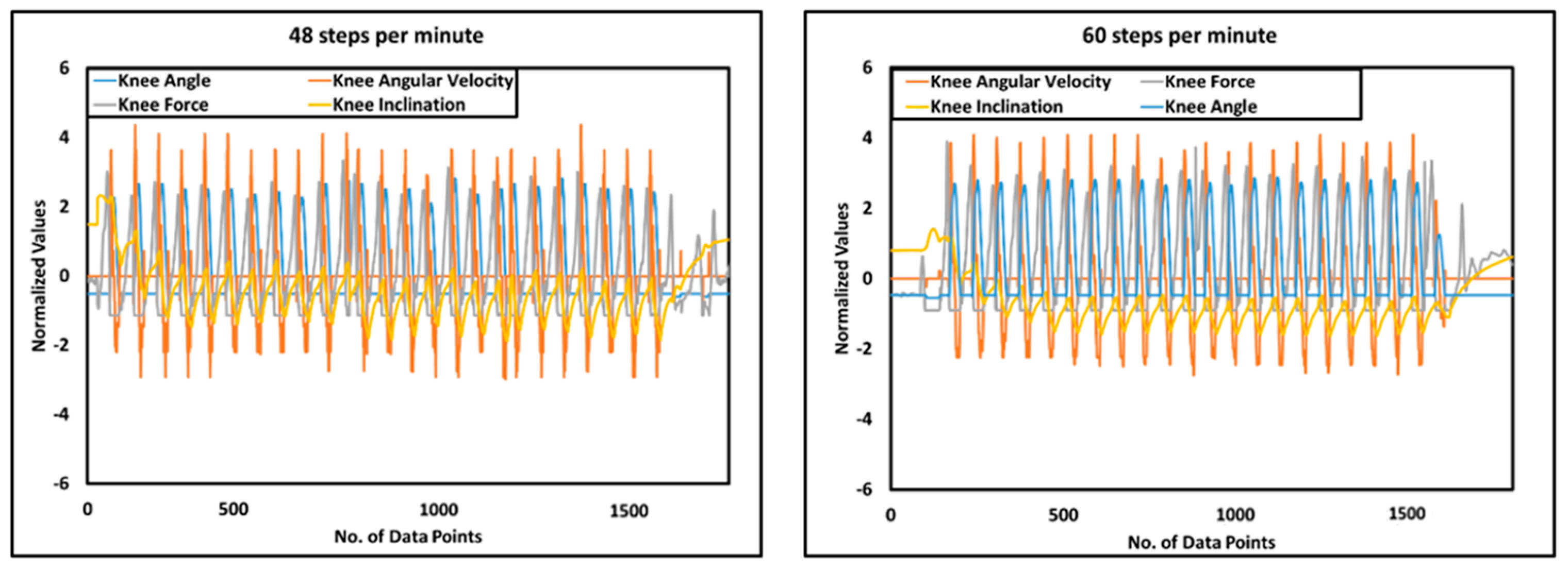
| 7 | Average step time | 1.2 s (48 steps/min) | 1.02 s (60 steps/min) | ||||
| 8 | Average speed | 0.66 m/s | 0.99 m/s | ||||
| Sr. # | Technical Features | Orion [57,58] | Pile [59,60] | Rheo [61,62] | Genium [63,64] | i-Inspire |
|---|---|---|---|---|---|---|
| 1 | Type of actuator | Hydraulic and pneumatic cylinder | Hydraulic cylinder | MR damping | Hydraulic cylinder | MR damping |
| 2 | Sensors | Piston stroke sensor; FSR; IMU | Inductive sensor; Strain gauges; load cell | Customized knee angle sensor; load cell; IMU | Knee angle sensor; load sensor; IMU | Knee angle sensor; strain Gauge; IMU |
| 3 | Walking controller | FSM variable damping | Two-point variable damping | FSM variable damping | FSM variable damping | FSM variable damping |
| 4 | Intent recognition | HRB approach, using timers, force sensor, and stroke sensor | HRB, using load cells and timers | HRB based on timers, load cell, and knee angle data | HRB based on sensory data | HRB, using IMU, strain gauge, and knee angle sensor |
| 5 | Modes | Sitting; standing; walking; RD; RA; SD; C; SR; K | Sitting; walking; standing; RD; SA; SR; UMI; C | Sitting; standing; walking; KL; RA; RD; K | Sitting; standing; walking; RA; RD; SA; SD | Sitting; standing; walking; knee Locking; SR (in-progress) |
| 6 | Cost | USD 30,000 | USD 30,000 | USD 40,000 | USD 60,000 | USD 1594 |
| Sr. # | Component | Price in USD | Total Price | |
|---|---|---|---|---|
| 1 | Electronics components | Voltage regulator—7812 and 7805 | 0.35 | 572.54 |
| 2 | Teensy 4.0 | 35.33 | ||
| 3 | MR damper | 511 | ||
| 4 | IMU MPU6050 | 1.24 | ||
| 5 | Strain gauge amplifier HX711 | 0.39 | ||
| 6 | DAC TLC5615 | 2.65 | ||
| 7 | Knee encoder (KY-040) | 0.39 | ||
| 8 | Battery 14 V 2200 mAH | 10.60 | ||
| 9 | Strain gauges—BF350 | 3.53 | ||
| 10 | LM358 with accessories | 1.77 | ||
| 11 | TIP-122 transistor | 0.35 | ||
| 12 | Bluetooth HC-05 | 3.53 | ||
| 13 | Wires, connectors | 1.41 | ||
| 14 | Mechanical components | Socket adaptor | 10.00 | 101.75 |
| 15 | Central shaft | 5.00 | ||
| 16 | Knee joint | 16.50 | ||
| 17 | Ball bearing (SKF-61903) | 13.50 | ||
| 18 | Knee chassis | 46.75 | ||
| 19 | Miscellaneous, including connecting bolts, drive gear, and driven gear | 10.00 | ||
| Cost of component | 674.29 | |||
| 19 | HR cost | 500.00 | ||
| 20 | Overhead | 101.15 | ||
| Cost price | 1275.44 | |||
| 21 | Profit @ 25% | 318.86 | ||
| Selling price | 1594.30 | |||
Disclaimer/Publisher’s Note: The statements, opinions and data contained in all publications are solely those of the individual author(s) and contributor(s) and not of MDPI and/or the editor(s). MDPI and/or the editor(s) disclaim responsibility for any injury to people or property resulting from any ideas, methods, instructions or products referred to in the content. |
© 2024 by the authors. Licensee MDPI, Basel, Switzerland. This article is an open access article distributed under the terms and conditions of the Creative Commons Attribution (CC BY) license (https://creativecommons.org/licenses/by/4.0/).
Share and Cite
Qadir, M.U.; Haq, I.U.; Khan, M.A.; Shah, K.; Chouikhi, H.; Ismail, M.A. Design, Analysis, and Development of Low-Cost State-of-the-Art Magnetorheological-Based Microprocessor Prosthetic Knee. Sensors 2024, 24, 255. https://doi.org/10.3390/s24010255
Qadir MU, Haq IU, Khan MA, Shah K, Chouikhi H, Ismail MA. Design, Analysis, and Development of Low-Cost State-of-the-Art Magnetorheological-Based Microprocessor Prosthetic Knee. Sensors. 2024; 24(1):255. https://doi.org/10.3390/s24010255
Chicago/Turabian StyleQadir, Muhammad Usman, Izhar Ul Haq, Muhammad Awais Khan, Kamran Shah, Houssam Chouikhi, and Mohamed A. Ismail. 2024. "Design, Analysis, and Development of Low-Cost State-of-the-Art Magnetorheological-Based Microprocessor Prosthetic Knee" Sensors 24, no. 1: 255. https://doi.org/10.3390/s24010255
APA StyleQadir, M. U., Haq, I. U., Khan, M. A., Shah, K., Chouikhi, H., & Ismail, M. A. (2024). Design, Analysis, and Development of Low-Cost State-of-the-Art Magnetorheological-Based Microprocessor Prosthetic Knee. Sensors, 24(1), 255. https://doi.org/10.3390/s24010255