
High Pulsed Voltage Alkaline Electrolysis for Water Splitting


Abstract
1. Introduction
2. State of the Art
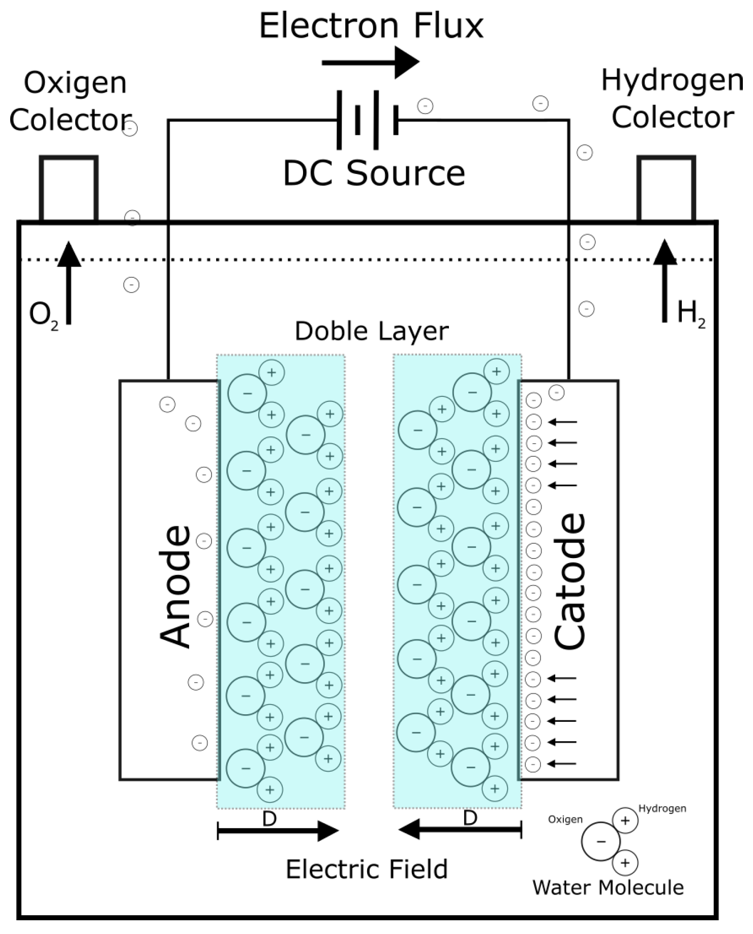
2.1. Electrolysis
2.2. Pulsed Electrolysis
2.3. High Voltage Electrolysis
3. Hydrogen Generator
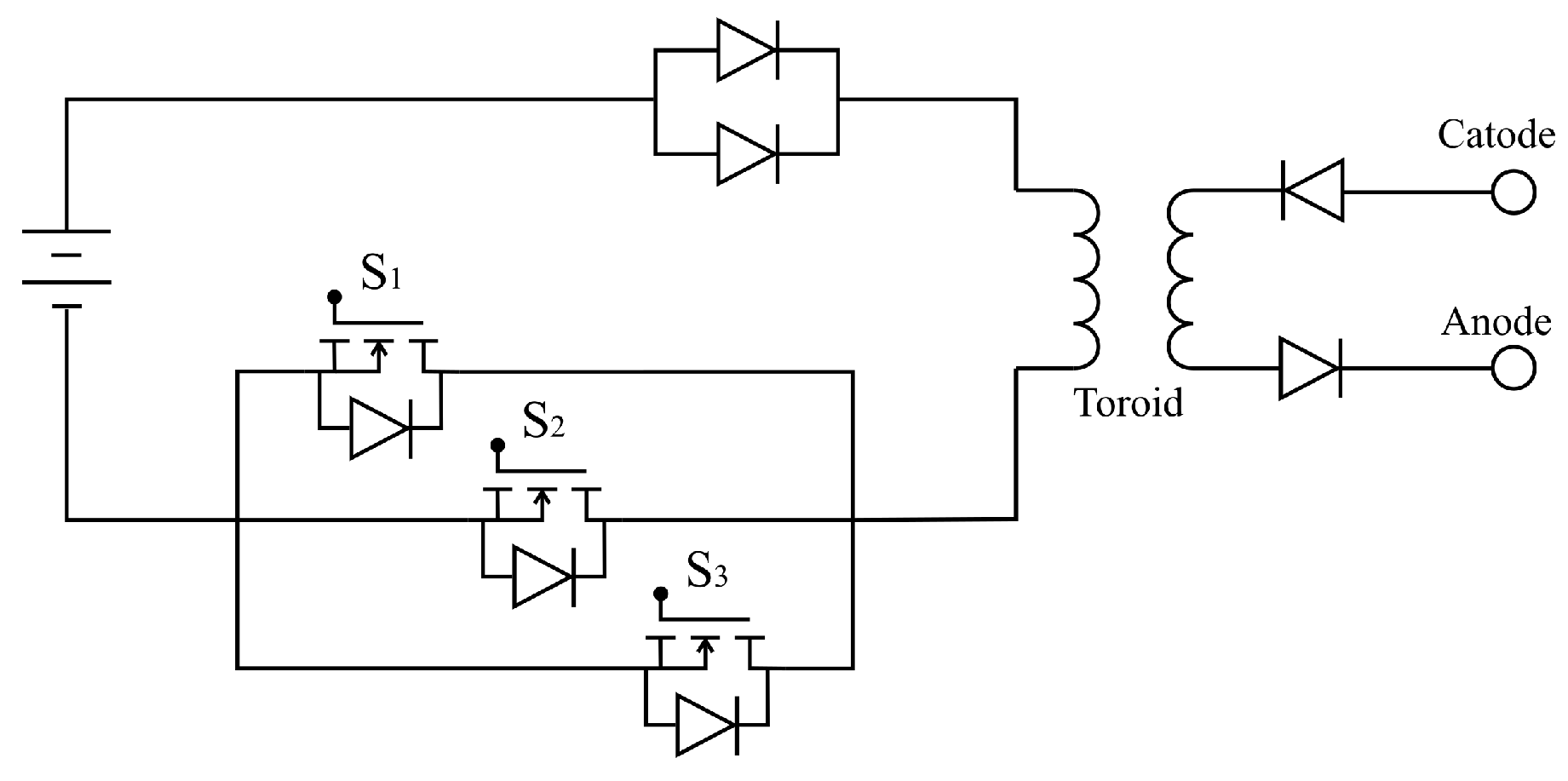
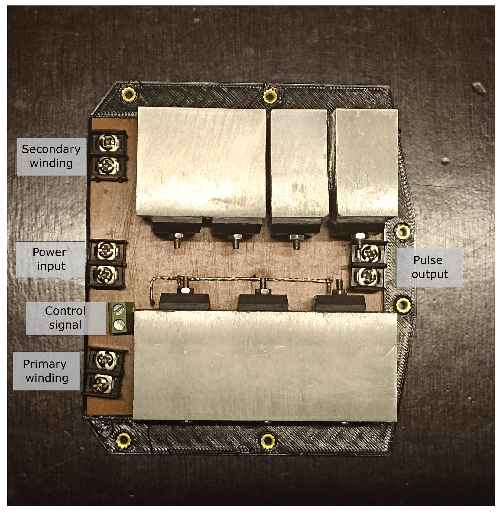
3.1. Circuit
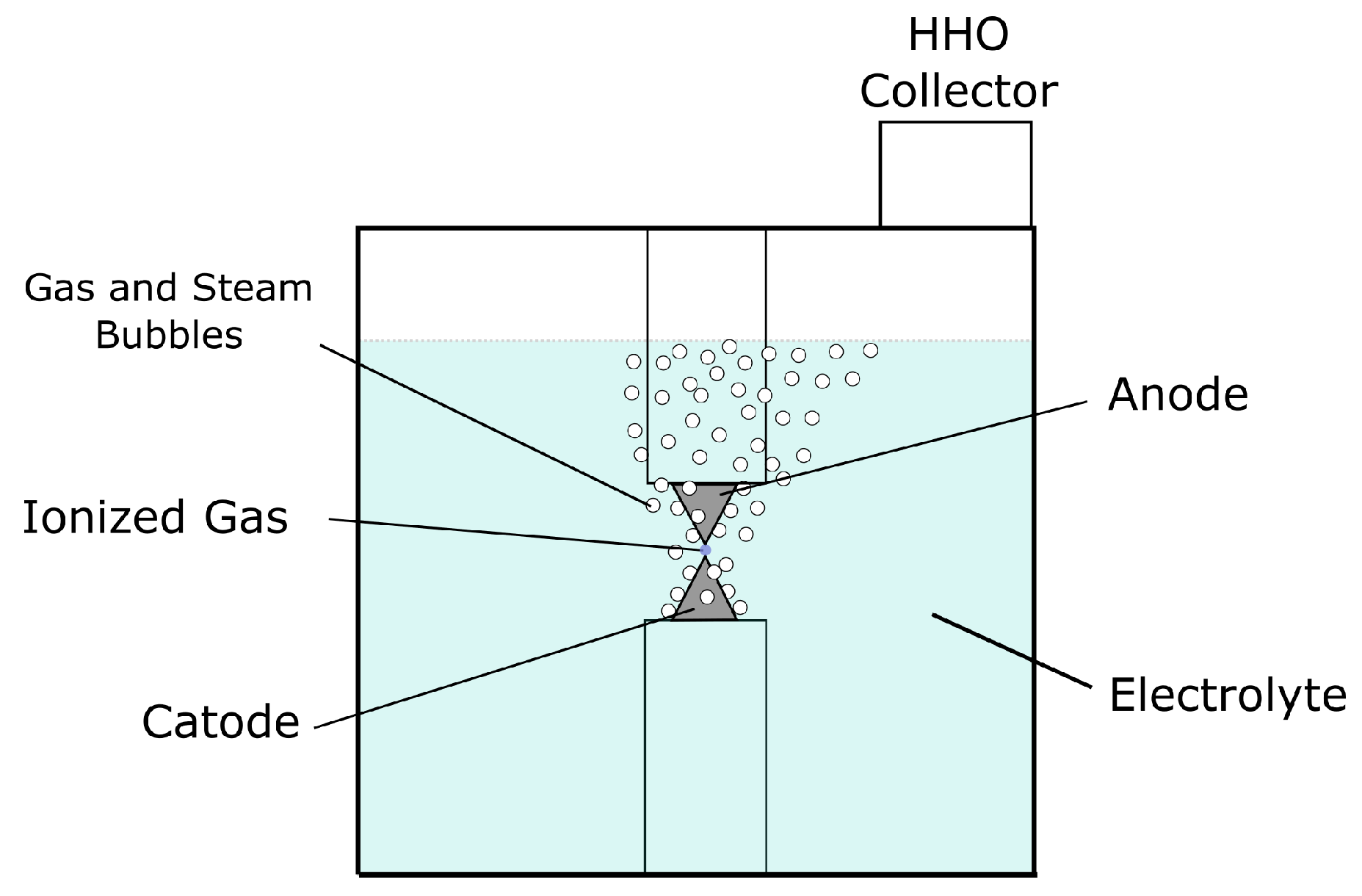
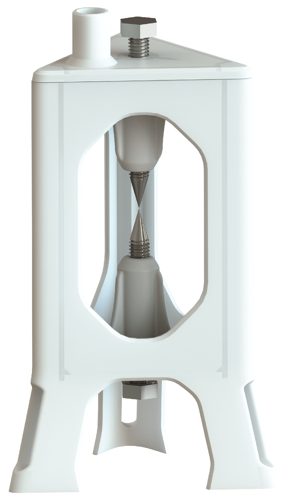
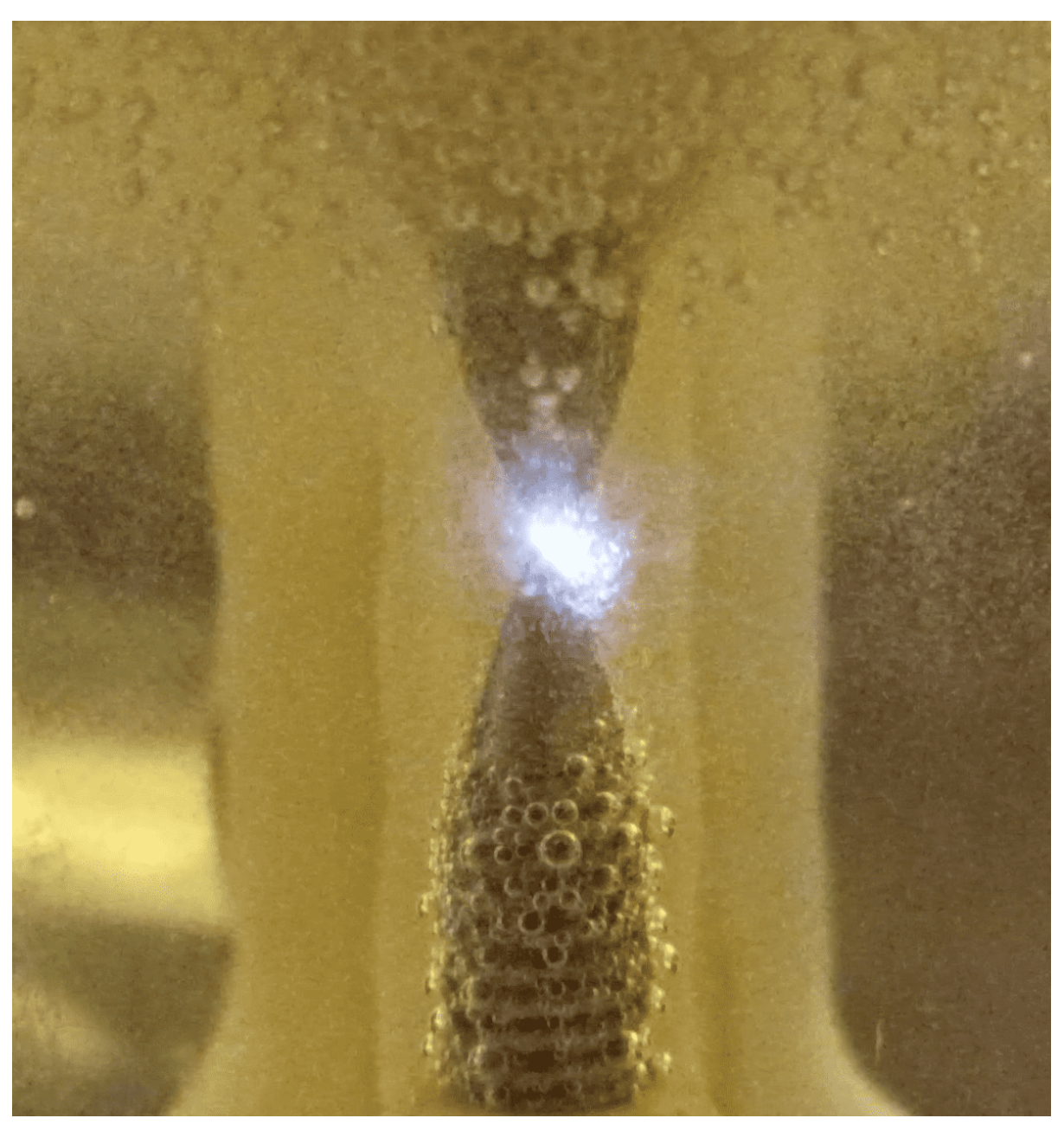
3.2. Plasmolysis Cell
4. Experimentation Method
4.1. Circuit
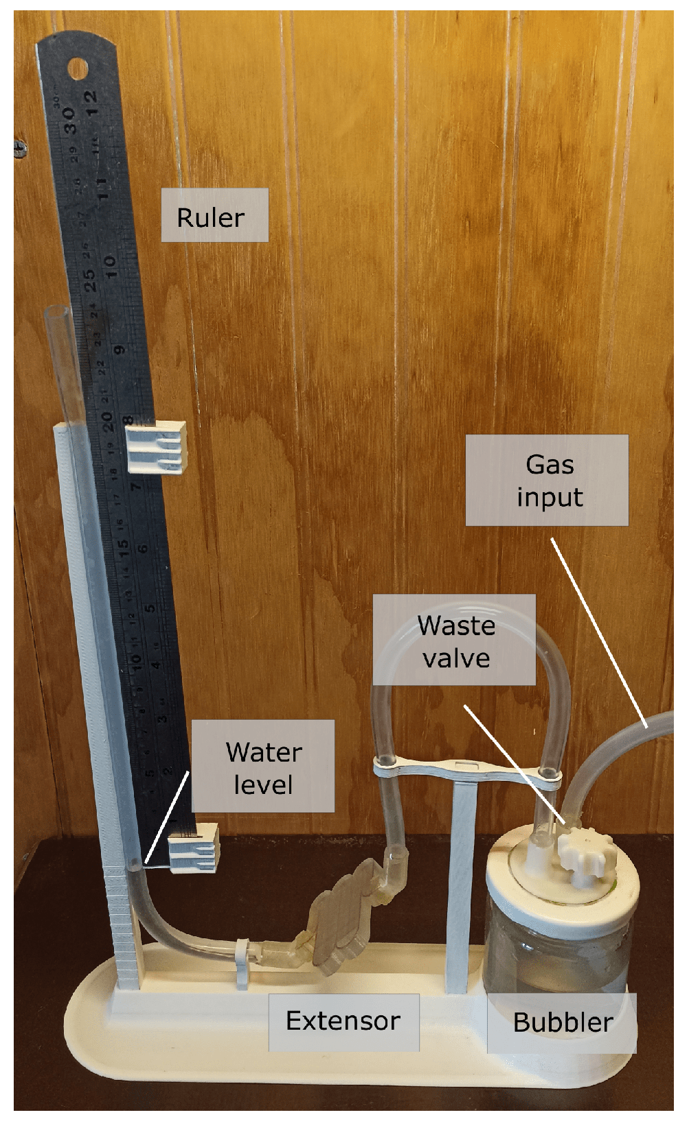
4.2. Measurement System
4.3. Electrolyte
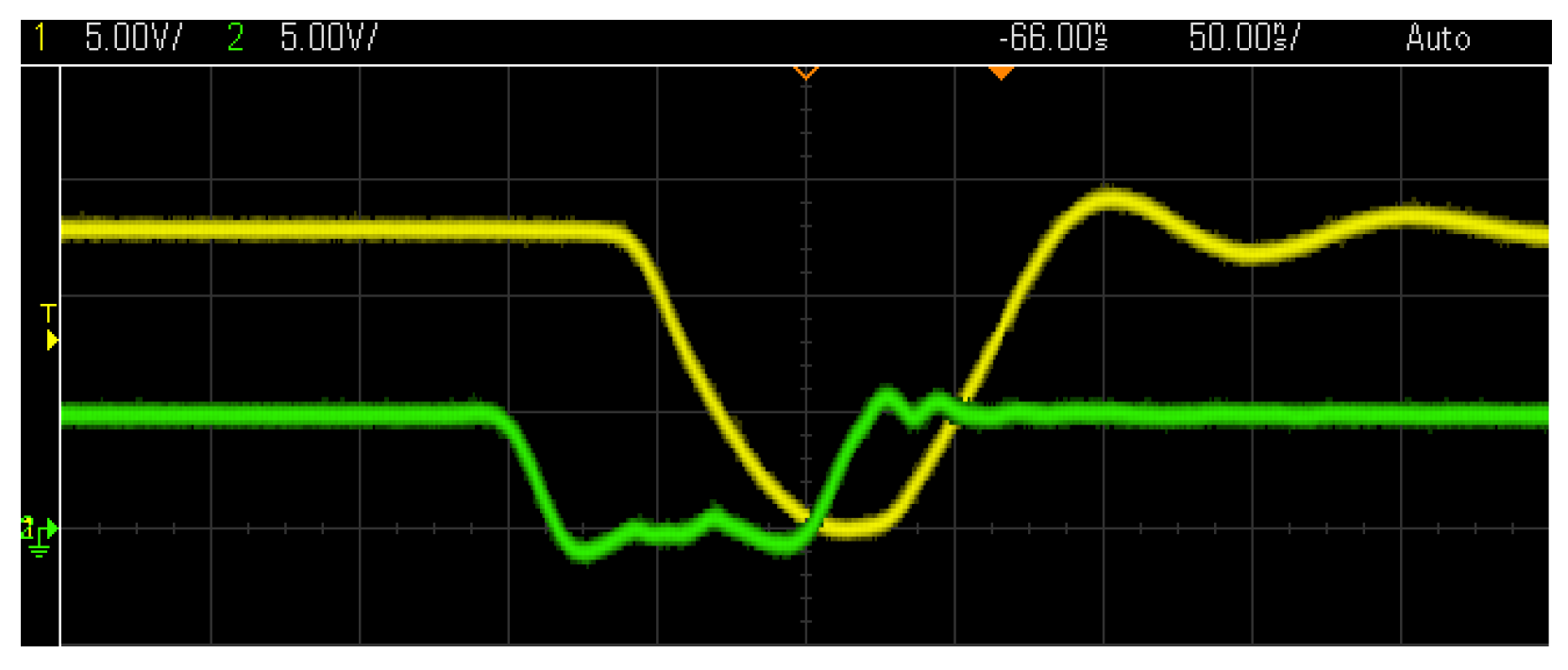
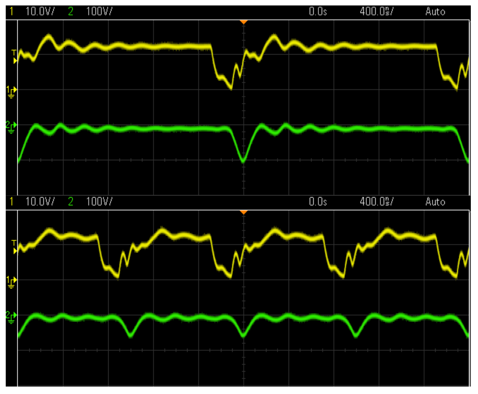
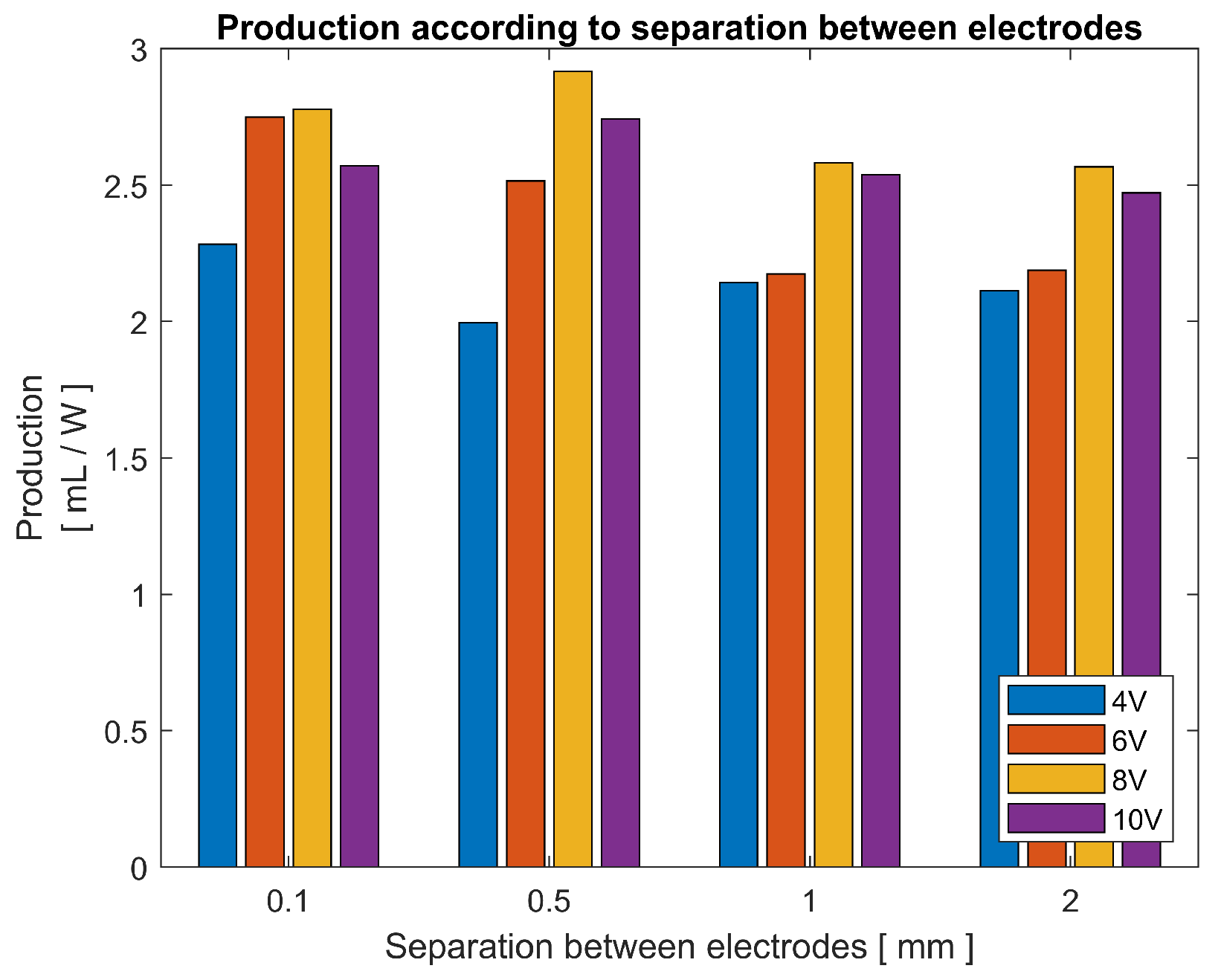
4.4. Results and Discussion
5. Conclusions
Author Contributions
Funding
Institutional Review Board Statement
Informed Consent Statement
Data Availability Statement
Acknowledgments
Conflicts of Interest
References
- Pascuzzi, S.; Anifantis, A.S.; Blanco, I.; Mugnozza, G.S. Electrolyzer Performance Analysis of an Integrated Hydrogen Power System for Greenhouse Heating. A Case Study; Department of Agricultural and Environmental Science (DiSAAT), University of Bari Aldo Moro: Bari, Italy, 2016. [Google Scholar]
- Arsalis, A.; Georghiou, G.E.; Papanastasiou, P. Recent Research Progress in Hybrid Photovoltaic–Regenerative Hydrogen Fuel Cell Microgrid Systems. Energies 2022, 15, 3512. [Google Scholar] [CrossRef]
- Shivaprasad, K.; Chitragar, P.; Kumar, G. Effect of Hydrogen Addition on Combustion and Emission Characteristics of High Speed Spark Ignition Engine—An Experimental Study; SAE Technical Paper 2015-01-1684; SAE International: Warrendale, PA, USA, 2015. [Google Scholar] [CrossRef]
- Bari, S.; Dewar, T.; Zhang, C. Performance and Emission Characteristics of a Diesel Engine with On-Board Produced Hydrogen-Oxygen Injection. Therm. Sci. Eng. Prog. 2022, 32, 101317. [Google Scholar] [CrossRef]
- Iza, F.; Walsh, J.L.; Kong, M.G. From Sub-microsecond to Nanosecond-Pulsed Atmospheric-Pressure Plasmas. IEEE Trans. Plasma Sci. 2009, 37, 1289–1296. [Google Scholar] [CrossRef]
- Mankowski, J.; Kristiansen, M. A Review of Short Pulse Generator Technology. IEEE Trans. Plasma Sci. 2000, 28, 102–108. [Google Scholar] [CrossRef]
- Kebriaei, M.; Ketabi, A.; Niasar, A.H. Pulsed Corona Discharge, a New and Effective Technique for Water and Air Treatment; Department of Electrical & Computer Engineering, University of Kashan: Kashan, Iran, 2015. [Google Scholar]
- Malik, M.A.; Ghaffar, A.; Malik, S.A. Water Purification by Electrical Discharges. Plasma Sources Sci. Technol. 2001, 10, 82. [Google Scholar] [CrossRef]
- Saksono, N.; Feryansyah, R.; Bismo, S. Hydrogen Production Using Non-Thermal Plasma Electrolysis in KOH Solution; Chemical Engineering Department, University of Indonesia: Kota Depok, Indonesia, 2011. [Google Scholar]
- Saksono, N.; Kartohardjono, S.; Yuniawati, T. High performance plasma electrolysis reactor for hydrogen generation using a NaOH-Methanol solution. Int. J. Technol. 2016, 7, 1421–1429. [Google Scholar] [CrossRef]
- Das, S.; Mishra, A.; Ghangrekar, M.M. Production of Hydrogen Peroxide Using Various Metal-Based Catalysts in Electrochemical and Bioelectrochemical Systems: Mini Review. American Society of Civil Engineers. J. Hazard. Toxic Radioact. Waste 2020, 24, 06020001. [Google Scholar] [CrossRef]
- Gupta, A.; Das, S.; Ghangrekar, M. Optimal Cathodic Imposed Potential and Appropriate Catalyst for the Synthesis of Hydrogen Peroxide in Microbial Electrolysis Cell; Department of Civil Engineering, Indian Institute of Technology Kharagpur: Kharagpur, India, 2020. [Google Scholar]
- Sequeira, C.A.C.; Santos, D.M.F. Hydrogen Production. CiêNcia Tecnol. Dos Mater. 2010. [Google Scholar] [CrossRef]
- Rashid, M.; Al Mesfer, M.K.; Naseem, H.; Danish, M. Hydrogen Production by Water Electrolysis: A Review of Alkaline Water Electrolysis, PEM Water Electrolysis and High Temperature Water Electrolysis. Int. J. Eng. Adv. Technol. (IJEAT) 2015, 4, 81–93. [Google Scholar]
- Ursúa, A.; Sanchis, P. Static-Dynamic Modelling of the Electrical Behaviour of a Commercial Advanced Alkaline Water Electrolyser; Department of Electrical and Electronic Engineering, Public University of Navarra, Campus de Arrosadía: Pamplona, Spain, 2012. [Google Scholar]
- Sequeira, C.A.C.; Santos, D.M.F.; Figueiredo, J.L. Hydrogen Production by Alkaline Water Electrolysis. Quim. Nova 2013, 36, 1176–1193. [Google Scholar]
- Gambou, F.; Guilbert, D.; Zasadzinski, M.; Rafaralahy, H. A Comprehensive Survey of Alkaline Electrolyzer Modeling: Electrical Domain and Specific Electrolyte Conductivity. Energies 2022, 15, 3452. [Google Scholar] [CrossRef]
- Drab, M.; Gongadze, E.; Mesarec, L.; Kralj, S.; Kralj-Iglic, V.; Iglic, A. The internal and external dipole moment of a water molecule and orientational ordering of water dipoles in an electric double layer. Elektrotehniski Vestn. 2017, 84, 221–234. [Google Scholar]
- Monk, N.; Watson, S. Review of pulsed power for efficient hydrogen production. Int. J. Hydrogen Energy 2016, 41, 7782–7791. [Google Scholar] [CrossRef]
- Mazloomi, K.; Sulaiman, N.; Moayedi, H. An Investigation into the Electrical Impedance of Water Electrolysis Cells—With a View to Saving Energy. Int. J. Electrochem. Sci. 2012, 7, 3466–3481. [Google Scholar]
- Shimizu, N.; Hotta, S.; Sekiya, T.; Oda, O. A novel method of hydrogen generation by water electrolysis using an ultra-short-pulse power supply. J. Appl. Electrochem. 2006, 36, 419–423. [Google Scholar] [CrossRef]
- Vanags, M.; Kleperis, J.; Bajars, G. Water Electrolysis with Inductive Voltage Pulses. In Electrolysis; Linkov, V., Kleperis, J., Eds.; InTechOpen: London, UK, 2012; Chapter 2. [Google Scholar]
- Mizuno, T.; Akimoto, T.; Azumi, K.; Ohmori, T.; Aoki, Y.; Takahashi, A. Hydrogen Evolution by Plasma Electrolysis in Aqueous Solution. Jpn. J. Appl. Phys. 2005, 44, 1A. [Google Scholar] [CrossRef]
- Boudesocquea, N.; Vandensteendamb, C.; Lafona, C.; Girolda, C.; Baronnetb, J. Hydrogen production by thermal water splitting using a thermal plasma. In Proceedings of the WHEC 16, Lyon, France, 13–16 June 2006. [Google Scholar]
- Grosse, K.; der Gathen, S.-V.; von Keudell, A. Nanosecond Pulsed Discharges in Distilled Water: I. Continuum Radiation and Plasma Ignition. Plasma Sources Sci. Technol. 2020, 29, 095008. [Google Scholar] [CrossRef]
- von Keudell, A.; Grosse, K.; von der Gathen, V.S. Nanosecond Pulsed Discharges in Distilled Water-Part II: Line Emission and Plasma Propagation. Plasma Sources Sci. Technol. 2020, 29, 085021. [Google Scholar] [CrossRef]
- Thivya, S.; Sree, V.G. Breakdown Study of Water with Different Conductivities. In Proceedings of the 13th IRF International Conference, Bengaluru, India, 24 May 2015. [Google Scholar]
- Dharmaraj, H.A. Energy saving in nano pulsed dc electrolysis for hydrogen production. Int. J. Environ. Sci. 2016, 6, 795–807. [Google Scholar]
- Huiskamp, T.; Voeten, S.J.; van Heesch, E.J.M.; Pemen, A.J.M. Design of a Subnanosecond Rise Time, Variable Pulse Duration, Variable Amplitude, Repetitive, High-Voltage Pulse Source. IEEE Trans. Plasma Sci. 2014, 42, 127–137. [Google Scholar] [CrossRef]
- Huiskamp, T.; Beckers, F.J.C.M.; van Heesch, E.J.M.; Pemen, A.J.M. First Implementation of a Subnanosecond Rise Time, Variable Pulse Duration, Variable Amplitude, Repetitive, High-Voltage Pulse Source. IEEE Trans. Plasma Sci. 2014, 42, 859–867. [Google Scholar] [CrossRef]


Disclaimer/Publisher’s Note: The statements, opinions and data contained in all publications are solely those of the individual author(s) and contributor(s) and not of MDPI and/or the editor(s). MDPI and/or the editor(s) disclaim responsibility for any injury to people or property resulting from any ideas, methods, instructions or products referred to in the content. |
© 2023 by the authors. Licensee MDPI, Basel, Switzerland. This article is an open access article distributed under the terms and conditions of the Creative Commons Attribution (CC BY) license (https://creativecommons.org/licenses/by/4.0/).
Share and Cite
Albornoz, M.; Rivera, M.; Wheeler, P.; Ramírez, R. High Pulsed Voltage Alkaline Electrolysis for Water Splitting. Sensors 2023, 23, 3820. https://doi.org/10.3390/s23083820
Albornoz M, Rivera M, Wheeler P, Ramírez R. High Pulsed Voltage Alkaline Electrolysis for Water Splitting. Sensors. 2023; 23(8):3820. https://doi.org/10.3390/s23083820
Chicago/Turabian StyleAlbornoz, Matías, Marco Rivera, Patrick Wheeler, and Roberto Ramírez. 2023. "High Pulsed Voltage Alkaline Electrolysis for Water Splitting" Sensors 23, no. 8: 3820. https://doi.org/10.3390/s23083820
APA StyleAlbornoz, M., Rivera, M., Wheeler, P., & Ramírez, R. (2023). High Pulsed Voltage Alkaline Electrolysis for Water Splitting. Sensors, 23(8), 3820. https://doi.org/10.3390/s23083820