
Distributed Intelligent Battery Management System Using a Real-World Cloud Computing System


Abstract
1. Introduction
1.1. Maintenance Particularities of Each Type of Battery
1.2. BMS Applications
1.3. Battery Modeling
1.4. Common Catastrophic Battery Failures
- Dry-out (loss-of-compression);
- Plate sulfation;
- Soft and hard shorts;
- Post leakage;
- Thermal runaway;
- Positive-grid corrosion.
2. Materials and Methods
2.1. Materials
2.1.1. Batteries
2.1.2. Xuncel Inverter
2.1.3. BlueSolar MPPT Regulator
- Initial charge (bulk): The solar charger uses its maximum charge current during the initial charge phase to quickly charge the batteries. The battery voltage will gradually rise during this stage. The initial charging phase of the battery ends when the voltage reaches the predetermined absorption voltage, and the absorption phase then starts.
- Absorption: The solar charger is now operating in constant voltage mode as it enters the absorption phase. The battery’s current will gradually drop. The absorption phase ends and the float phase starts when the current drops below 1 A (tail current). The absorption time is brief when there are only surface discharges. This stops the battery from being overcharged. The absorption time is automatically extended to ensure that the battery is fully charged following a deep discharge.
- Float: The batteries are fully charged during the float phase when the voltage is decreased.
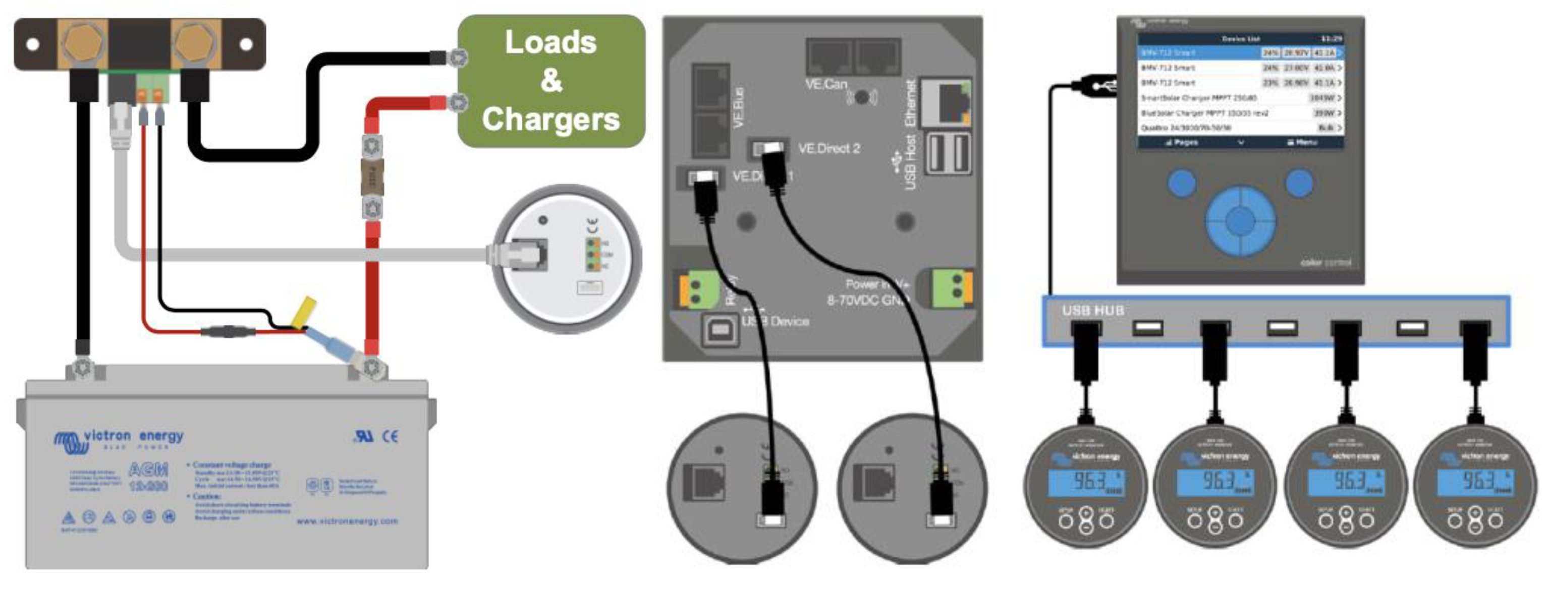
2.1.4. BMV-712 Smart Battery Monitor
External Temperature Sensor
- -
- Battery voltage;
- -
- Voltage of the auxiliary battery;
- -
- Input current (without sign)/output current (with sign -);
- -
- Power drawn (sign -)/power added (unsigned);
- -
- Ampere hours consumed: Ah quantity (with sign -);
- -
- SOC (0–100%);
- -
- Remaining autonomy (h);
- -
- Battery temperature (°C/°F).
2.1.5. Cerbo GX General Control Device
Victron Connect-Remote App
Cerbo GX General Control Device with Temperature Sensors
2.2. Methods
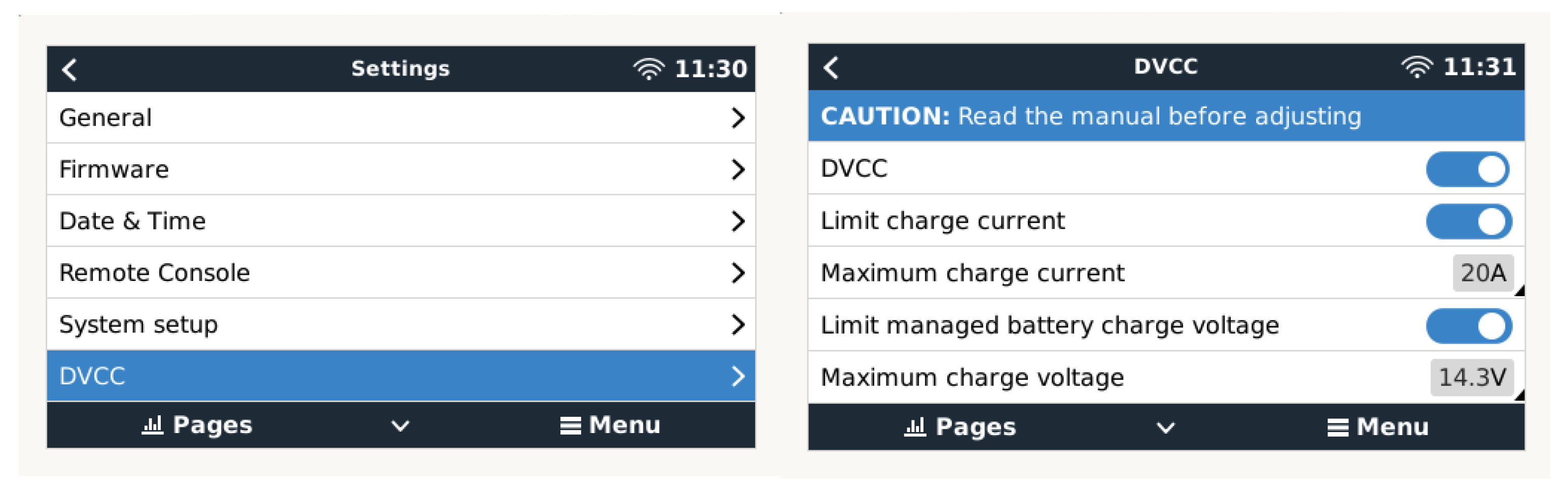
2.2.1. Distributed Voltage and Current Control (DVCC) Functions
- -
- The SVS is enabled when DVCC is enabled. It works with solar chargers connected to a VE.Direct port. The system automatically selects the best available voltage measurement obtained from the BMV-712 battery monitor. To make up for the voltage loss in the battery wires, the battery voltage data are used. This prevents a lower voltage from charging the battery than the exact voltage set on the charger owing to wiring resistance.
- -
- The STS will use the BMV-712 to obtain the battery temperature value for the Cerbo GX controller device to send the obtained temperature measurement to the inverter/charger system and all connected solar chargers. The battery temperature data are used to adjust the charging voltages. At low temperatures, a lead–acid battery generally needs a higher charging voltage, and conversely, a lower charging voltage is required at high temperatures. When using lithium batteries, the charging voltages are the same at all temperatures, except at low temperatures. Below 5 °C, they should not be charged to prevent damage and degradation; therefore, they should be disconnected from the generation source.
- -
- The SCS sends the battery current, measured by the BMV-712 battery monitor connected to the GX device, to all connected solar chargers. The battery current data are used to enable more precise usage of the tail current setting because it helps the solar charger determine when the absorption phase should end and transition to the equalization/float phase. However, it should be noted that gel batteries such as those used in this work are generally not suitable for the equalization phase.
2.2.2. Alarm, Acoustic Signals, and Relay Management
2.2.3. Dynamic Model of System Operation
3. Results
- -
- Battery voltage;
- -
- Battery SOC;
- -
- Battery current;
- -
- Battery and inverter temperature.
3.1. Battery Charging
3.2. Supplementary Charge Conditioned by Current Consumption
- Initial charge: In the first (bulk) phase of charging, all available current from the solar charger is used to charge the battery to the absorption voltage of 14.4 V. In this phase, a gel battery is charged to about 85%.
- Absorption: During this phase, an absorption voltage of 14.4 V is maintained for a variable time that is set by the solar charger algorithm, taking into account the information supplied by the BMS-712 device regarding the initial state of charge of the battery, and can be up to 5 times longer than the duration of the bulk phase. The charging current is gradually reduced until the float current is reached.
- Float: Once the absorption phase is finished, after a time that will depend on the battery charging algorithm selected in the MPPT solar charge controller, the flotation phase is reached. At this moment, the battery is considered 100% charged. In the case of a 12 V battery, the BMV resets to “fully charged” when the following “charging parameters” are met: the voltage exceeds 13.2 V, and simultaneously, the charging (tail) current is lowered to 4.0% of the full battery capacity. In the case of the type of 200 Ah battery used in this work, it is 8 A for 3 min. Once this state of charge is reached, the VictronConnect application executes automatic synchronization, reaching 100% SOC. Synchronization can also be optionally executed by the user using the configuration sequence shown in Figure 19. Once the first synchronization is completed (automatically or manually), the BMV keeps a record of the automatic synchronizations that occur (Figure 19).
3.3. Test Management on High/Low-Temperature Alarm Threshold Values
4. Discussion
5. Conclusions
Supplementary Materials
Author Contributions
Funding
Institutional Review Board Statement
Informed Consent Statement
Data Availability Statement
Conflicts of Interest
Abbreviations
| AGM | Absorbent Glass Mat |
| BMS | Battery management system |
| BMV | Battery Monitoring Victron |
| Cap | Battery’s current capacity |
| C-rate | Discharge velocity |
| COM | Common pin |
| DC+ | DC power supply positive pole |
| DC− | DC power supply negative pole |
| DOD | Depth of discharge |
| DVCC | Distributed voltage and current control |
| ESS | Energy storage system |
| I | Current parameter |
| KOH | Potassium hydroxide |
| LiFePO4 | Lithium iron phosphate |
| MPPT | Maximum power point tracking controller |
| NC | Normally closed pin |
| NiCd | Nickel–cadmium |
| NO | Normally opened pin |
| OCV | Open-circuit voltage |
| PNs | Petri Nets |
| PRV | Pressure relief valve |
| PV | Photovoltaic |
| R | Resistance |
| RC | Resistance capacitor |
| RUL | Battery remaining useful life |
| SCC | Solar charge controller |
| SCS | Shared current sensor |
| SOC | State of charge |
| SOE | State of energy |
| SOH | State of health |
| SOP | State of power |
| STS | Shared temperature sensor |
| S1 | Switch Channel 1 Relay |
| S2 | Switch Channel 2 Relay |
| T | Temperature parameter |
| V | Voltage parameter |
| VRLA | Valve-Regulated Lead–Acid |
| VRM | Victron Remote Monitoring |
References
- Bopp, G.; Gabler, H.; Sauer, D.; Jossen, A.; Mittermeier, J.; Bachler, M.; Sprau, P.; Willer, B.; Wollny, M. A Systematic Effort to Define Evaluation and Performance Parameters and Criteria for Lead Acid batteries in PV Systems. In Proceedings of the 13th European Photovoltaic Solar Energy Conference, Nice, France, 23–27 October 1995; pp. 1763–1769. [Google Scholar]
- Markvart, T. Solar Electricity England; John Wiley & Sons: Hoboken, NJ, USA, 1994. [Google Scholar]
- Duryea, S.; Islam, S.; Lawrance, W. A battery management system for stand alone photovoltaic energy systems. In Proceedings of the Conference Record of the 1999 IEEE Industry Applications Conference, Phoenix, Arizona, USA, 3–7 October 1999; Thirty-Forth IAS Annual Meeting (Cat. No. 99CH36370). Volume 4, pp. 2649–2654. [Google Scholar]
- Lead Acid Battery Working–Lifetime Study. Available online: http://www.power-thru.com/documents/The%20Truth%20About%20Batteries%20-%20POWERTHRU%20White%20Paper.pdf (accessed on 12 July 2019).
- Lee, C.Y.; Peng, H.C.; Lee, S.J.; Hung, I.; Hsieh, C.T.; Chiou, C.S.; Chang, Y.-M.; Huang, Y.P. A flexible three-in-one microsensor for real-time monitoring of internal temperature, voltage and current of lithium batteries. Sensors 2015, 15, 11485–11498. [Google Scholar] [CrossRef] [PubMed]
- Hong, J.; Wang, Z.; Liu, P. Big-Data-Based Thermal Runaway Prognosis of Battery Systems for Electric Vehicles. Energies 2017, 10, 919. [Google Scholar] [CrossRef]
- Jouhara, H.; Khordehgah, N.; Serey, N.; Almahmoud, S.; Lester, S.P.; Machen, D.; Wrobel, L. Applications and thermal management of rechargeable batteries for industrial applications. Energy 2019, 170, 849–861. [Google Scholar] [CrossRef]
- Sidhu, A.; Izadian, A.; Anwar, S. Adaptive nonlinear model-based fault diagnosis of Li-ion batteries. IEEE Trans. Ind. Electron. 2014, 62, 1002–1011. [Google Scholar] [CrossRef]
- García, E.; Quiles, E.; Correcher, A.; Morant, F. Marine NMEA 2000 Smart Sensors for Ship Batteries Supervision and Predictive Fault Diagnosis. Sensors 2019, 19, 4480. [Google Scholar] [CrossRef]
- Available online: https://www.victronenergy.com/upload/documents/BMV-712_Smart/9172-Manual_BMV_and_SmartShunt-pdf-en.pdf (accessed on 15 March 2023).
- Dorn, R.; Schwartz, R.; Steurich, B. Battery Management System. In Lithium-Ion Batteries: Basics and Applications; Springer: Berlin, Heidelberg, 2018; pp. 165–175. [Google Scholar]
- Jiang, Z.; Jia, Q.; Guan, X. On large action space in EV charging scheduling optimization. Sci. China Inform. Sci. 2022, 65, 122201. [Google Scholar] [CrossRef]
- Liu, H.; Wei, Z.; He, W. Thermal issues about Li-ion batteries and recent progress in battery thermal management systems: A review. Energy Convers. Manag. 2017, 150, 304–330. [Google Scholar] [CrossRef]
- Wang, Y.; Zhang, C.; Chen, Z.; Xie, J.; Zhang, X. A novel active equalization method for lithium-ion batteries in electric vehicles. Appl. Energy 2015, 145, 36–42. [Google Scholar] [CrossRef]
- Jia, S.; Ma, B.; Guo, W.; Li, Z.S. A sample entropy based prognostics method for lithium- ion batteries using relevance vector machine. J. Manuf. Syst. 2021, 11, 2169–2189. [Google Scholar] [CrossRef]
- Tran, M.-K.; Fowler, M. Sensor Fault Detection and Isolation for Degrading Lithium-Ion Batteries in Electric Vehicles Using Parameter Estimation with Recursive Least Squares. Batteries 2020, 6, 1. [Google Scholar] [CrossRef]
- Hu, X.; Zhang, K.; Liu, K.; Lin, X.; Dey, S.; Onori, S. Advanced Fault Diagnosis for Lithium-Ion Battery Systems: A Review of Fault Mechanisms, Fault Features, and Diagnosis Procedures. IEEE Ind. Electron. Mag. 2020, 14, 65–91. [Google Scholar] [CrossRef]
- Wang, Y.; Tian, J.; Chen, Z.; Liu, X. Model based insulation fault diagnosis for lithium-ion battery pack in electric vehicles. Measurement 2019, 131, 443–451. [Google Scholar] [CrossRef]
- Wang, Y.; Chen, Z. A framework for state-of-charge and remaining discharge time prediction using unscented particle filter. Appl. Energy 2020, 260, 114324. [Google Scholar] [CrossRef]
- Wang, Y.; Zhang, C.; Chen, Z. A method for joint estimation of state-of-charge and available energy of LiFePO4 batteries. Appl. Energy 2014, 135, 81–87. [Google Scholar] [CrossRef]
- He, H.; Zhang, Y.; Xiong, R.; Wang, C. A novel Gaussian model based battery state estimation approach: State-of-energy. Appl. Energy 2015, 151, 41–48. [Google Scholar] [CrossRef]
- Wang, Y.; Pan, R.; Liu, C.; Chen, Z.; Ling, Q. Power capability evaluation for lithium iron phosphate batteries based on multi-parameter constraints estimation. J. Power Sources 2018, 374, 12–23. [Google Scholar] [CrossRef]
- Dong, G.; Han, W.; Wang, Y. Dynamic Bayesian network based lithium-ion battery health prognosis for electric vehicles. IEEE Trans. Ind. Electron. 2020, 68, 10949–10958. [Google Scholar] [CrossRef]
- Wang, Y.; Xu, R.; Zhou, C.; Kang, X.; Chen, Z. Digital twin and cloud-side-end collaboration for intelligent battery management system. J. Manuf. Syst. 2022, 62, 124–134. [Google Scholar] [CrossRef]
- Gabbar, H.A.; Othman, A.M.; Abdussami, M.R. Review of Battery Management Systems (BMS) Development and Industrial Standards. Technologies 2021, 9, 28. [Google Scholar] [CrossRef]
- Arnieri, E.; Boccia, L.; Amoroso, F.; Amendola, G.; Cappuccino, G. Improved Efficiency Management Strategy for Battery-Based Energy Storage Systems. Electronics 2019, 8, 1459. [Google Scholar] [CrossRef]
- Sumsurooah, S.; He, Y.; Torchio, M.; Kouramas, K.; Guida, B.; Cuomo, F.; Atkin, J.; Bozhko, S.; Renzetti, A.; Russo, A.; et al. ENIGMA—A Centralised Supervisory Controller for Enhanced Onboard Electrical Energy Management with Model in the Loop Demonstration. Energies 2021, 14, 5518. [Google Scholar] [CrossRef]
- Aiello, O. Electromagnetic Susceptibility of Battery Management Systems’ ICs for Electric Vehicles: Experimental Study. Electronics 2020, 9, 510. [Google Scholar] [CrossRef]
- PRIMES: An Intelligent Power Regulation Using Innovative Modules for Energy Supervision. Available online: https://cordis.europa.eu/article/id/173624-smart-control-of-aircraft-electrical-loads (accessed on 11 March 2023).
- More Open Electrical Technologies (MOET). Available online: https://cordis.europa.eu/project/id/30861 (accessed on 11 March 2023).
- EPOCAL: An Electrical POwer Center for Aeronautical Loads. Available online: https://cordis.europa.eu/project/id/323408 (accessed on 11 March 2023).
- Canciello, G.; Cavallo, A.; Schiavo, A.L.; Russo, A. Multi-objective adaptive sliding manifold control for More Electric Aircraft. ISA Trans. 2020, 107, 316–328, ISSN 0019-0578. [Google Scholar] [CrossRef] [PubMed]
- Ramkumar, M.S.; Reddy, C.S.R.; Ramakrishnan, A.; Raja, K.; Pushpa, S.; Jose, S.; Jayakumar, M. Review on Li-Ion Battery with Battery Management System in Electrical Vehicle. Adv. Mater. Sci.Eng. 2022, 2022, 3379574. [Google Scholar] [CrossRef]
- Lipu, M.S.H.; Hannan, M.A.; Karim, T.F.; Hussain, A.; Saad, M.H.M.; Ayob, A.; Miah, M.S.; Indra Mahlia, T.M. Intelligent algorithms and control strategies for battery management system in electric vehicles: Progress, challenges and future outlook. J. Clean.Prod. 2021, 292, 126044, ISSN 0959-6526. [Google Scholar] [CrossRef]
- Casals, L.C.; García, B.A.; Benítez, M.M.G. Aging model for re-used electric vehicle batteries in second life stationary applications. In Project Management and Engineering Research; Springer: Cham, Switzerland, 2017; pp. 139–151. [Google Scholar]
- Salameh, Z.M.; Casacca, M.A.; Lynch, W.A. A mathematical model for lead-acid batteries. IEEE Trans. Energy Convers. 1992, 7, 93–98. [Google Scholar] [CrossRef]
- Copetti, J.B.; Lorenzo, E.; Chenlo, F. A general battery model for PV system simulation. Prog. Photovolt. Res. Appl. 1993, 1, 283–292. [Google Scholar] [CrossRef]
- Ceraolo, M. New dynamical models of lead-acid batteries. IEEE Trans. Power Syst. 2000, 15, 1184–1190. [Google Scholar] [CrossRef] [PubMed]
- Chen, M.; Rincon-Mora, G.A. Accurate electrical battery model capable of predicting runtime and IV performance. IEEE Trans. Energy Convers. 2006, 21, 504–511. [Google Scholar] [CrossRef]
- Gomadam, P.M.; Weidner, J.W.; Dougal, R.A.; White, R.E. Mathematical modeling of lithium-ion and nickel battery systems. J. Power Sources 2002, 110, 267–284. [Google Scholar] [CrossRef]
- Zhang, J.; Lee, J. A review on prognostics and health monitoring of Li-ion battery. J. Power Sources 2011, 196, 6007–6014. [Google Scholar] [CrossRef]
- Cho, S.; Jeong, H.; Han, C.; Jin, S.; Lim, J.H.; Oh, J. State-of-charge estimation for lithium-ion batteries under various operating conditions using an equivalent circuit model. Comput. Chem. Eng. 2012, 41, 1–9. [Google Scholar] [CrossRef]
- Xu, J.; Wang, J.; Li, S.; Cao, B. A method to simultaneously detect the current sensor fault and estimate the state of energy for batteries in electric vehicles. Sensors 2016, 16, 1328. [Google Scholar] [CrossRef] [PubMed]
- Osaka, T.; Momma, T.; Mukoyama, D.; Nara, H. Proposal of novel equivalent circuit for electrochemical impedance analysis of commercially available lithium ion battery. J. Power Sources 2012, 205, 483–486. [Google Scholar] [CrossRef]
- Liu, W.; Delacourt, C.; Forgez, C.; Pelissier, S. Study of graphite/NCA Li-ion Cell Degradation During Accelerated Aging Tests—Data Analysis of the SimStock Project. In Proceedings of the 2011 IEEE Vehicle Power and Propulsion Conference, Chicago, IL, USA, 6–9 September 2011; pp. 1–6. [Google Scholar]
- Guenther, C.; Barillas, J.K.; Stumpp, S.; Danzer, M.A. Adynamic battery model for simulation of battery-to-grid applications. In Proceedings of the 2012 3rd IEEE PES Innovative Smart Grid Technologies Europe (ISGT Europe), Berlin, Germany, 14–17 October 2012; pp. 1–7. [Google Scholar]
- Worwood, D.; Kellner, Q.; Wojtala, M.; Widanage, W.D.; McGlen, R.; Greenwood, D.; Marco, J. A new approach to the internal thermal management of cylindrical battery cells for automotive applications. J. Power Sources 2017, 346, 151–166. [Google Scholar] [CrossRef]
- Lai, T.C.; Tsang, K.F.; Liu, Y.; Lai, L.L. A Temperature Prediction Method of Valve-regulated Lead-acid Battery. In Proceedings of the 2019 IEEE 28th International Symposium on Industrial Electronics (ISIE), Vancouver, BC, Canada, 12–14 June 2019; pp. 2467–2470. [Google Scholar]
- Barré, A.; Deguilhem, B.; Grolleau, S.; Gérard, M.; Suard, F.; Riu, D. A review on lithium-ion battery ageing mechanisms and estimations for automotive applications. J. Power Sources 2013, 241, 680–689. [Google Scholar] [CrossRef]
- Eddahech, A. Modelisation duVieillissement et Determination de l’Etat de Sante de Batteries Lithium-Ion pour Application Vehicule Electrique et Hybride. Available online: https://tel.archives-ouvertes.fr/tel-00957678 (accessed on 12 July 2019).
- Vetter, J.; Nov, P.; Wagner, M.R.R.; Veit, C.; Novák, P.; Möller, K.-C.; Hammouche, A. Ageing mechanisms in lithium-ion batteries. J. Power Sources 2005, 147, 269–281. [Google Scholar] [CrossRef]
- Laidler, K.J. The development of the Arrhenius equation. J. Chem. Educ. 1984, 61, 494. [Google Scholar] [CrossRef]
- Schmalstieg, J.; Käbitz, S.; Ecker, M.; Sauer, D.U. A holistic aging model for Li(NiMnCo)O2 based 18650 lithium-ion batteries. J. Power Sources 2014, 257, 325–334. [Google Scholar] [CrossRef]
- Delaille, A.; Grolleau, S.; Duclaud, F. SIMCAL Project: Calendar aging results obtained on a panel of 6 commercial Li-ion cells. In Proceedings of the Electrochemical Energy Summit de l’Electrochemical Society, San Francisco, CA, USA, 27–28 October 2013; Volume 101. [Google Scholar]
- Guena, T.; Leblanc, P. How Depth of Discharge A ects the Cycle Life of Lithium-Metal-Polymer Batteries. In Proceedings of the INTELEC 06—Twenty-Eighth International Telecommunications Energy Conference, Providence, RI, USA, 10–14 September 2006; pp. 1–8. [Google Scholar]
- Sarasketa-Zabala, E.; Laresgoiti, I.; Alava, I.; Rivas, M.; Villarreal, I.; Blanco, F. Validation of the methodology for lithium-ion batteries lifetime prognosis. In Proceedings of the EVS27 Electric Vehicle Symposium 2013, Barcelona, Spain, 17–20 November 2013; pp. 1–12. [Google Scholar]
- Lam, L. A Practical Circuit based Model for State of Health Estimation of Li ion Battery Cells in Electric Vehicles. Master’s Thesis, University of Technology Delft, Delft, Switzerland, 2011. [Google Scholar]
- Nieho, P.; Kraemer, E.; Winter, M. Parametrisation of the influence of di erent cycling conditions on the capacity fade and the internal resistance increase for lithium nickel manganese cobalt oxide/graphite cells. J. Electroanal. Chem. 2013, 707, 110–116. [Google Scholar]
- Goebel, K.; Saha, B.; Saxena, A.; Celaya, J.R.; Christophersen, J.P. Prognostics in battery health management. IEEE Instrum. Meas. Mag. 2008, 11, 33–40. [Google Scholar] [CrossRef]
- Nuhic, A.; Terzimehic, T.; Soczka-Guth, T.; Buchholz, M.; Dietmayer, K. Health diagnosis and remaining useful life prognostics of lithium-ion batteries using data-driven methods. J. Power Sources 2013, 239, 680–688. [Google Scholar] [CrossRef]
- Zou, Y.; Hu, X.; Ma, H.; Li, S.E. Combined State of Charge and State of Health estimation over lithium-ion battery cell cycle lifespan for electric vehicles. J. Power Sources 2015, 273, 793–803. [Google Scholar] [CrossRef]
- Dai, H.; Wei, X.; Sun, Z. A new SOH prediction concept for the power lithium-ion battery used on HEVs. In Proceedings of the 5th IEEE Vehicle Power and Propulsion Conference, VPPC 09, Dearborn, MI, USA, 7–10 September 2009; pp. 1649–1653. [Google Scholar]
- Zainuri, A.; Wibawa, U.; Rusli, M.; Hasanah, R.N.; Harahap, R.A. VRLA battery state of health estimation based on charging time. Telkomnika 2019, 17, 1577–1583. [Google Scholar] [CrossRef]
- NASA-STD-8070.5; Trend Analysis Technique. NASA: Washington, DC, USA, 1988.
- May, G.J.; Davidson, A.; Monahov, B. Lead batteries for utility energy storage: A review. J. Energy Storage 2018, 15, 145–157. [Google Scholar] [CrossRef]
- Megger Batery Testing Guide. art.nr. ZP-AD01E Doc. AD0009AE 2009. Available online: https://us.megger.com/support/technical-library?searchtext=&searchmode=anyword&application2=0&type=6;&application=0&order=0 (accessed on 10 October 2019).
- McCluer, S. Battery Technology for Data Centers and Network Rooms: Lead-Acid Battery Options; APC White Paper; Schneider Electric: Rueil-Malmaison, France, 2011; Volume 30. [Google Scholar]
- Technical Manual for Chairman Series Batteries; Concorde Battery Corporation: West Covina, CA, USA, 2017.
- Catherino, H.A. Complexity in battery systems: Thermal runaway in VRLA batteries. J. Power Sources 2006, 158, 977–986. [Google Scholar] [CrossRef]
- Culpin, B. Thermal runaway in valve-regulated lead-acid cells and the e ect of separator structure. J. Power Sources 2004, 133, 79–86. [Google Scholar] [CrossRef]
- Ho, C.M.; Steves, K. Newinsights into thermal runaway of valve regulated lead-acid batteries. In Proceedings of the International Stationary Battery Conference, Battcon, Miami Beach, FL, USA; Available online: https://www.sbsbattery.com/PDFs/VRLAThermRunawayStorageBatterySystems.pdf (accessed on 10 October 2019).
- McCluer, S. Battery Technology for Data Centers and Network Rooms: VRLA Reliability and Safety; Schneider Electric: Rueil-Malmaison, France, 2012. [Google Scholar]
- Feder, D.O.; Hlavac, M.J. Analysis and interpretation of conductance measurements used to assess the state-of-health of valve regulated lead acid batteries. In Proceedings of the Intelec 94, Vancouver, BC, Canada, 30 October–3 November 1994; pp. 282–291. [Google Scholar]
- Cotton, C.B.; Sheppard, D.; Lim, R.; Cotton, S.D.; Jump, M. System and Method for Remote Monitoring of Battery Condition. U.S. Patent 7,768,238, 18 August 2009. [Google Scholar]
- Deshpande, S.; Shaffer, D.; Szymborski, J.; Barling, L.; Hawkins, J. Intelligent monitoring system satisfies customer needs for continuous monitoring and assurance on VRLA batteries. In Proceedings of the 21st International Telecommunications Energy Conference. INTELEC’99, Copenhagen, Denmark, 9 June 1999; p. 557. [Google Scholar]
- Kim, T.; Makwana, D.; Adhikaree, A.; Vagdoda, J.; Lee, Y. Cloud-Based Battery Condition Monitoring and Fault Diagnosis Platform for Large-Scale Lithium-Ion Battery Energy Storage Systems. Energies 2018, 11, 125. [Google Scholar] [CrossRef]
- Li, W.; Rentemeister, M.; Badeda, J.; Jöst, D.; Schulte, D.; Sauer, D.U. Digital twin for battery systems: Cloud battery management system with online state-of-charge and state-of-health estimation. J. Energy Storage 2020, 30, 101557. [Google Scholar] [CrossRef]
- Yang, S.; Zhang, Z.; Cao, R.; Wang, M.; Cheng, H.; Zhang, L.; Jiang, Y.; Li, Y.; Chen, B.; Ling, H.; et al. Implementation for a cloud battery management system based on the CHAIN framework. Energy AI 2021, 5, 100088. [Google Scholar] [CrossRef]
- Tran, M.K.; Panchal, S.; Khang, T.D.; Panchal, K.; Fraser, R.; Fowler, M. Concept review of a cloud-based smart battery management system for lithium-ion batteries: Feasibility, logistics, and functionality. Batteries 2022, 8, 19. [Google Scholar] [CrossRef] [PubMed]
- García, E.; Quiles, E.; Correcher, A.; Morant, F. Predictive Diagnosis Based on Predictor Symptoms for Isolated Photovoltaic Systems Using MPPT Charge Regulators. Sensors 2022, 22, 7819. [Google Scholar] [CrossRef] [PubMed]
- Rusch, W.; Vassallo, K.; Hart, G. Understanding the Real Differences Between GEL and AGM Batteries-You Can’t Change Physics. 2007. Available online: https://www.baebatteriesusa.com/wp-content/uploads/2019/03/Understanding-The-Real-Differences-Between-Gel-AGM-Batteries-Rusch-2007.pdf (accessed on 15 March 2023).
- Liu, K.; Li, K.; Peng, Q.; Zhang, C. A brief review on key technologies in the battery management system of electric vehicles. Front. Mech. Eng. 2019, 14, 47–64. [Google Scholar] [CrossRef]


| Actuation Management | Alarm Treatment |
|---|---|
|
|
|
|
|
|
|
|
|
|
|
|
|
|
|
|
|
|
|
|
| Timestamp | Gateway [0] | Gateway [0] | Gateway [0] | Battery Monitor [278] | Battery Monitor [278] | Battery Monitor [278] | Battery Monitor [278] | Battery Monitor [278] |
|---|---|---|---|---|---|---|---|---|
| UTC (+00:00) | Relay 1 State | CCGX Relay 2 State | Generator Run Reason | Voltage | Current | Battery Temperature | State of Charge | Low Voltage Alarm |
| V | A | C | % | |||||
| 2023-02-17 07:17:45 | Closed | Open | Battery voltage | 12.18 | −0.7 | 11 | 88.8 | Alarm |
| 2023-02-17 07:18:45 | Closed | Open | Battery voltage | 12.2 | −0.2 | 11 | 88.8 | Alarm |
| 2023-02-17 07:19:45 | Closed | Open | Battery voltage | 12.19 | −0.2 | 11 | 88.8 | Alarm |
| 2023-02-17 07:20:45 | Closed | Open | Battery voltage | 12.2 | −0.3 | 11 | 88.8 | Alarm |
| 2023-02-17 07:21:46 | Closed | Open | Battery voltage | 12.2 | −0.3 | 11 | 88.8 | Alarm |
| 2023-02-17 07:22:45 | Closed | Open | Battery voltage | 12.21 | −0.2 | 11 | 88.8 | Alarm |
| 2023-02-17 07:23:45 | Closed | Open | Battery voltage | 12.22 | −0.2 | 11 | 88.8 | Alarm |
| 2023-02-17 07:24:45 | Closed | Open | Battery voltage | 12.2 | 0.5 | 11 | 88.8 | Alarm |
| 2023-02-17 07:25:46 | Closed | Open | Battery voltage | 12.24 | 0.5 | 11 | 88.8 | Alarm |
| 2023-02-17 07:26:45 | Closed | Open | Battery voltage | 12.28 | 0.8 | 11 | 88.8 | Alarm |
| 2023-02-17 07:27:45 | Closed | Open | Battery voltage | 12.29 | 0.7 | 11 | 88.8 | Alarm |
| 2023-02-17 07:28:45 | Closed | Open | Battery voltage | 12.32 | 1 | 10 | 88.8 | Alarm |
| 2023-02-17 07:29:45 | Closed | Open | Battery voltage | 12.18 | −3 | 10 | 88.8 | Alarm |
| 2023-02-17 07:30:46 | Closed | Open | Battery voltage | 12.3 | 1.1 | 10 | 88.8 | Alarm |
| 2023-02-17 07:31:45 | Closed | Open | Battery voltage | 12.34 | 1.2 | 10 | 88.8 | Alarm |
| 2023-02-17 07:32:45 | Closed | Open | Battery voltage | 12.35 | 1.2 | 10 | 88.8 | Alarm |
| 2023-02-17 07:33:45 | Closed | Open | Battery voltage | 12.37 | 1.5 | 10 | 88.8 | Alarm |
| 2023-02-17 07:34:45 | Closed | Open | Battery voltage | 12.39 | 1.5 | 10 | 88.8 | Alarm |
| 2023-02-17 07:35:46 | Closed | Open | Battery voltage | 12.35 | 1.5 | 10 | 88.8 | Alarm |
| 2023-02-17 07:36:45 | Closed | Open | Battery voltage | 12.39 | 1.3 | 11 | 88.8 | Alarm |
| 2023-02-17 07:36:54 | Closed | Open | Battery voltage | 12.4 | 1.8 | 10 | 88.8 | No alarm |
| 2023-02-17 07:37:45 | Closed | Open | Battery voltage | 12.42 | 1.7 | 10 | 88.8 | No alarm |
| 2023-02-17 07:38:45 | Closed | Open | Battery voltage | 12.45 | 1.9 | 11 | 88.8 | No alarm |
| 2023-02-17 07:39:46 | Closed | Open | Battery voltage | 12.48 | 1.9 | 10 | 88.8 | No alarm |
| 2023-02-17 07:40:45 | Closed | Open | Battery voltage | 12.34 | −2.2 | 10 | 88.8 | No alarm |
| 2023-02-17 07:41:45 | Closed | Open | Battery voltage | 12.48 | 2.4 | 10 | 88.8 | No alarm |
| 2023-02-17 07:42:45 | Closed | Open | Battery voltage | 12.51 | 2.2 | 10 | 88.9 | No alarm |
| 2023-02-17 07:43:45 | Closed | Open | Battery voltage | 12.55 | 2.6 | 10 | 88.9 | No alarm |
| 2023-02-17 07:44:45 | Closed | Open | Battery voltage | 12.57 | 2.6 | 11 | 88.9 | No alarm |
| 2023-02-17 07:45:45 | Closed | Open | Battery voltage | 12.59 | 2.6 | 10 | 88.9 | No alarm |
| 2023-02-17 07:46:45 | Closed | Open | Battery voltage | 12.54 | 2.4 | 11 | 88.9 | No alarm |
| 2023-02-17 07:47:45 | Closed | Open | Battery voltage | 12.59 | 2.7 | 11 | 88.9 | No alarm |
| 2023-02-17 07:48:45 | Closed | Open | Battery voltage | 12.62 | 2.8 | 11 | 88.9 | No alarm |
| 2023-02-17 07:49:46 | Closed | Open | Battery voltage | 12.64 | 2.9 | 11 | 89 | No alarm |
| 2023-02-17 07:50:45 | Closed | Open | Battery voltage | 12.65 | 3.1 | 11 | 89 | No alarm |
| 2023-02-17 07:51:45 | Closed | Open | Battery voltage | 12.52 | −0.9 | 11 | 89 | No alarm |
| 2023-02-17 07:52:45 | Closed | Open | Battery voltage | 12.64 | 3.3 | 11 | 89 | No alarm |
| Timestamp | Gateway [0] | Gateway [0] | Gateway [0] | Battery Monitor [278] | Battery Monitor [278] | Battery Monitor [278] | Battery Monitor [278] | Battery Monitor [278] |
|---|---|---|---|---|---|---|---|---|
| UTC (+00:00) | Relay 1 State | CCGX Relay 2 State | Generator Run Reason | Voltage | Current | Battery Temperature | State of Charge | Low Voltage Alarm |
| V | A | C | % | |||||
| 2023-02-17 10:07:45 | Closed | Open | Battery voltage | 14.18 | 14.7 | 14 | 96.4 | No alarm |
| 2023-02-17 10:08:46 | Closed | Open | Battery voltage | 14.01 | 14.6 | 14 | 96.5 | No alarm |
| 2023-02-17 10:09:45 | Closed | Open | Battery voltage | 14.21 | 14.6 | 14 | 96.6 | No alarm |
| 2023-02-17 10:10:45 | Closed | Open | Battery voltage | 14.22 | 14.6 | 14 | 96.7 | No alarm |
| 2023-02-17 10:11:45 | Closed | Open | Battery voltage | 14.28 | 14.6 | 14 | 96.8 | No alarm |
| 2023-02-17 10:12:11 | Open | Open | Stopped | 14.31 | 14.6 | 14 | 96.8 | No alarm |
| 2023-02-17 10:12:12 | Open | Open | Stopped | 14.31 | 14.6 | 14 | 96.8 | No alarm |
| 2023-02-17 10:12:46 | Open | Open | Stopped | 13.03 | −1.4 | 14 | 96.8 | No alarm |
| 2023-02-17 10:13:15 | Closed | Open | Battery current | 12.86 | −5.9 | 14 | 96.8 | No alarm |
| 2023-02-17 10:13:16 | Closed | Open | Battery current | 12.86 | −5.9 | 14 | 96.8 | No alarm |
| 2023-02-17 10:13:45 | Closed | Open | Battery current | 13.64 | 14.6 | 14 | 96.8 | No alarm |
| 2023-02-17 10:13:47 | Closed | Open | Stopped | 13.53 | 13.1 | 14 | 96.8 | No alarm |
| 2023-02-17 10:13:48 | Open | Open | Stopped | 13.38 | 11.7 | 14 | 96.8 | No alarm |
| 2023-02-17 10:14:45 | Open | Open | Stopped | 12.88 | −1.5 | 14 | 96.8 | No alarm |
| 2023-02-17 10:15:45 | Open | Open | Stopped | 12.84 | −1.4 | 14 | 96.8 | No alarm |
| 2023-02-17 10:16:45 | Open | Open | Stopped | 12.82 | −1.4 | 14 | 96.8 | No alarm |
| 2023-02-17 10:17:45 | Open | Open | Stopped | 12.81 | −1.4 | 14 | 96.8 | No alarm |
| 2023-02-17 10:18:07 | Closed | Open | Battery current | 12.73 | −5.9 | 14 | 96.8 | No alarm |
| 2023-02-17 10:18:08 | Closed | Open | Battery current | 12.72 | −6 | 14 | 96.8 | No alarm |
| 2023-02-17 10:18:09 | Closed | Open | Battery current | 12.72 | −6 | 14 | 96.8 | No alarm |
| 2023-02-17 10:18:32 | Open | Open | Stopped | 13.55 | 14.5 | 14 | 96.8 | No alarm |
| 2023-02-17 10:18:33 | Open | Open | Stopped | 13.42 | 10.4 | 14 | 96.8 | No alarm |
| 2023-02-17 10:18:45 | Open | Open | Stopped | 12.88 | −1.4 | 14 | 96.8 | No alarm |
| 2023-02-17 10:19:45 | Open | Open | Stopped | 12.8 | −1.5 | 14 | 96.8 | No alarm |
| 2023-02-17 10:20:46 | Open | Open | Stopped | 12.78 | −1.4 | 14 | 100 | No alarm |
| 2023-02-17 10:21:45 | Open | Open | Stopped | 12.77 | −1.5 | 14 | 100 | No alarm |
| 2023-02-17 10:22:45 | Open | Open | Stopped | 12.76 | −1.4 | 14 | 100 | No alarm |
| 2023-02-17 10:22:54 | Closed | Open | Battery current | 12.69 | −5.9 | 14 | 100 | No alarm |
| 2023-02-17 10:22:55 | Closed | Open | Battery current | 12.68 | −6 | 14 | 100 | No alarm |
| 2023-02-17 10:23:18 | Closed | Open | Stopped | 13.41 | 13.3 | 14 | 100 | No alarm |
| 2023-02-17 10:23:19 | Open | Open | Stopped | 13.32 | 12.9 | 14 | 100 | No alarm |
| 2023-02-17 10:23:45 | Open | Open | Stopped | 12.81 | −1.4 | 14 | 100 | No alarm |
| 2023-02-17 10:24:45 | Open | Open | Stopped | 12.77 | −1.4 | 14 | 100 | No alarm |
| 2023-02-17 10:25:45 | Open | Open | Stopped | 12.75 | −1.4 | 14 | 100 | No alarm |
| 2023-02-17 10:26:45 | Open | Open | Stopped | 12.75 | −1.5 | 14 | 100 | No alarm |
| 2023-02-17 10:27:43 | Closed | Open | Battery current | 12.66 | −6 | 14 | 100 | No alarm |
| 2023-02-17 10:27:44 | Closed | Open | Battery current | 12.66 | −6.1 | 14 | 100 | No alarm |
| 2023-02-17 10:27:45 | Closed | Open | Battery current | 12.66 | −6.1 | 14 | 100 | No alarm |
| 2023-02-17 10:28:08 | Open | Open | Stopped | 13.62 | 14.5 | 14 | 100 | No alarm |
| 2023-02-17 10:28:09 | Open | Open | Stopped | 13.49 | 12.9 | 14 | 100 | No alarm |
| 2023-02-17 10:28:46 | Open | Open | Stopped | 12.78 | −1.4 | 14 | 100 | No alarm |
| 2023-02-17 10:29:45 | Open | Open | Stopped | 12.74 | −1.4 | 14 | 100 | No alarm |
| Timestamp | Battery Monitor [278] | Battery Monitor [278] | Battery Monitor [278] | Battery Monitor [278] |
|---|---|---|---|---|
| UTC (+00:00) | Battery Temperature | Low Voltage Alarm | High Battery Temperature Alarm | Relay Status |
| C | ||||
| 2023-02-18 19:16:47 | 27 | No alarm | No alarm | Open |
| 2023-02-18 19:17:47 | 23 | No alarm | No alarm | Open |
| 2023-02-18 19:18:47 | 22 | No alarm | No alarm | Open |
| 2023-02-18 19:19:47 | 21 | No alarm | No alarm | Open |
| 2023-02-18 19:20:47 | 22 | No alarm | No alarm | Open |
| 2023-02-18 19:21:48 | 23 | No alarm | No alarm | Open |
| 2023-02-18 19:22:47 | 26 | No alarm | No alarm | Open |
| 2023-02-18 19:23:47 | 32 | No alarm | No alarm | Open |
| 2023-02-18 19:24:47 | 45 | No alarm | Alarm | Closed |
| 2023-02-18 19:24:58 | 45 | No alarm | Alarm | Closed |
| 2023-02-18 19:24:59 | 45 | No alarm | Alarm | Closed |
| 2023-02-18 19:25:47 | 44 | No alarm | Alarm | Closed |
| 2023-02-18 19:26:47 | 39 | No alarm | Alarm | Closed |
| 2023-02-18 19:27:12 | 38 | No alarm | No alarm | Open |
| 2023-02-18 19:27:47 | 36 | No alarm | No alarm | Open |
| 2023-02-18 19:28:48 | 32 | No alarm | No alarm | Open |
| 2023-02-18 19:29:47 | 29 | No alarm | No alarm | Open |
| 2023-02-18 19:29:53 | 29 | No alarm | No alarm | Open |
| 2023-02-18 19:29:56 | 29 | No alarm | No alarm | Open |
| 2023-02-18 19:29:58 | 27 | No alarm | No alarm | Open |
| 2023-02-18 19:30:47 | 26 | No alarm | No alarm | Open |
| 2023-02-18 19:31:47 | 24 | No alarm | No alarm | Open |
| 2023-02-18 19:32:47 | 23 | No alarm | No alarm | Open |
| 2023-02-18 19:33:47 | 22 | No alarm | No alarm | Open |
| 2023-02-18 19:34:47 | 22 | No alarm | No alarm | Open |
| 2023-02-18 19:35:47 | 21 | No alarm | No alarm | Open |
| 2023-02-18 19:36:47 | 21 | No alarm | No alarm | Open |
| 2023-02-18 19:37:47 | 20 | No alarm | No alarm | Open |
| 2023-02-18 19:38:47 | 20 | No alarm | No alarm | Open |
| 2023-02-18 19:39:47 | 20 | No alarm | No alarm | Open |
| 2023-02-18 19:40:47 | 20 | No alarm | No alarm | Open |
| 2023-02-18 19:41:47 | 19 | No alarm | No alarm | Open |
| 2023-02-18 19:42:47 | 19 | No alarm | No alarm | Open |
| 2023-02-18 19:43:47 | 19 | No alarm | No alarm | Open |
| 2023-02-18 19:44:47 | 19 | No alarm | No alarm | Open |
| 2023-02-18 19:45:47 | 19 | No alarm | No alarm | Open |
| 2023-02-18 19:46:47 | 18 | No alarm | No alarm | Open |
| Timestamp | Gateway [0] | Gateway [0] | Temperature Sensor [24] | Solar Charger [277] | Solar Charger [278] | Solar Charger [288] | Solar Charger [289] | System Overview [0] | Temperature Sensor [25] |
|---|---|---|---|---|---|---|---|---|---|
| UTC (+00:00) | Relay 1 State | Relay 2 State | Temperature | MPPT State | MPPT State | MPPT State | MPPT State | PV - DC-Coupled | Temperature |
| C | W | C | |||||||
| 2023-02-19 10:05:48 | Closed | Open | 18 | Voltage or current limited | Voltage or current limited | Voltage or current limited | Voltage or current limited | 29 | 15 |
| 2023-02-19 10:06:02 | Closed | Open | 18 | Voltage or current limited | Voltage or current limited | Voltage or current limited | Voltage or current limited | 29 | 15 |
| 2023-02-19 10:06:49 | Closed | Open | 18 | MPPT active | Voltage or current limited | Voltage or current limited | Voltage or current limited | 135 | 15 |
| 2023-02-19 10:07:48 | Closed | Open | 18 | MPPT active | Voltage or current limited | Voltage or current limited | Voltage or current limited | 127 | 15 |
| 2023-02-19 10:08:48 | Closed | Open | 18 | MPPT active | Voltage or current limited | Voltage or current limited | Voltage or current limited | 117 | 15 |
| 2023-02-19 10:09:48 | Closed | Open | 20 | MPPT active | Voltage or current limited | Voltage or current limited | Voltage or current limited | 121 | 15 |
| 2023-02-19 10:10:48 | Closed | Open | 21 | MPPT active | Voltage or current limited | Voltage or current limited | Voltage or current limited | 113 | 15 |
| 2023-02-19 10:11:49 | Closed | Open | 20 | MPPT active | Voltage or current limited | Voltage or current limited | Voltage or current limited | 112 | 15 |
| 2023-02-19 10:12:48 | Closed | Open | 20 | MPPT active | Voltage or current limited | Voltage or current limited | Voltage or current limited | 109 | 15 |
| 2023-02-19 10:13:48 | Closed | Open | 20 | MPPT active | Voltage or current limited | Voltage or current limited | Voltage or current limited | 147 | 15 |
| 2023-02-19 10:14:48 | Closed | Open | 19 | MPPT active | Voltage or current limited | Voltage or current limited | Voltage or current limited | 108 | 15 |
| 2023-02-19 10:15:48 | Closed | Open | 19 | MPPT active | Voltage or current limited | Voltage or current limited | Voltage or current limited | 106 | 15 |
| 2023-02-19 10:16:48 | Closed | Open | 19 | MPPT active | Voltage or current limited | Voltage or current limited | Voltage or current limited | 102 | 15 |
| 2023-02-19 10:17:48 | Closed | Open | 19 | MPPT active | Voltage or current limited | Voltage or current limited | Voltage or current limited | 105 | 15 |
| 2023-02-19 10:18:48 | Closed | Open | 19 | MPPT active | Voltage or current limited | Voltage or current limited | Voltage or current limited | 109 | 15 |
| 2023-02-19 10:19:48 | Closed | Open | 19 | MPPT active | Voltage or current limited | Voltage or current limited | Voltage or current limited | 104 | 15 |
| 2023-02-19 10:20:48 | Closed | Open | 19 | MPPT active | Voltage or current limited | Voltage or current limited | Voltage or current limited | 100 | 15 |
| 2023-02-19 10:21:49 | Closed | Open | 20 | MPPT active | Voltage or current limited | Voltage or current limited | Voltage or current limited | 101 | 15 |
| 2023-02-19 10:22:48 | Closed | Open | 21 | MPPT active | Voltage or current limited | Voltage or current limited | Voltage or current limited | 150 | 15 |
| 2023-02-19 10:23:48 | Closed | Open | 23 | MPPT active | Voltage or current limited | Voltage or current limited | Voltage or current limited | 106 | 15 |
| 2023-02-19 10:24:48 | Closed | Open | 25 | MPPT active | Voltage or current limited | Voltage or current limited | Voltage or current limited | 100 | 15 |
| 2023-02-19 10:25:49 | Closed | Open | 27 | MPPT active | Voltage or current limited | Voltage or current limited | Voltage or current limited | 96 | 15 |
| 2023-02-19 10:26:48 | Closed | Open | 29 | MPPT active | Voltage or current limited | Voltage or current limited | Voltage or current limited | 96 | 15 |
| 2023-02-19 10:27:48 | Closed | Open | 30 | MPPT active | Voltage or current limited | Voltage or current limited | Voltage or current limited | 100 | 15 |
| 2023-02-19 10:28:48 | Closed | Open | 30 | MPPT active | Voltage or current limited | Voltage or current limited | Voltage or current limited | 97 | 15 |
| 2023-02-19 10:29:48 | Closed | Open | 29 | MPPT active | Voltage or current limited | Voltage or current limited | Voltage or current limited | 96 | 15 |
| 2023-02-19 10:30:48 | Closed | Open | 30 | MPPT active | Voltage or current limited | Voltage or current limited | Voltage or current limited | 93 | 15 |
| 2023-02-19 10:31:48 | Closed | Open | 39 | MPPT active | Voltage or current limited | Voltage or current limited | Voltage or current limited | 139 | 15 |
| 2023-02-19 10:31:54 | Closed | Closed | 40 | MPPT active | Voltage or current limited | Voltage or current limited | Voltage or current limited | 138 | 15 |
| 2023-02-19 10:32:48 | Closed | Closed | 44 | Off | Off | Off | Off | 0 | 15 |
| 2023-02-19 10:33:48 | Closed | Closed | 47 | Off | Off | Off | Off | 0 | 15 |
| 2023-02-19 10:34:49 | Closed | Closed | 42 | Off | Off | Off | Off | 0 | 15 |
| 2023-02-19 10:35:43 | Closed | Open | 38 | Off | Off | Off | Off | 0 | 15 |
| 2023-02-19 10:35:48 | Closed | Open | 38 | Voltage or current limited | Voltage or current limited | Voltage or current limited | Voltage or current limited | 61 | 15 |
| 2023-02-19 10:36:46 | Closed | Open | 35 | Voltage or current limited | Voltage or current limited | Voltage or current limited | Voltage or current limited | 139 | 15 |
| 2023-02-19 10:36:48 | Closed | Open | 35 | Voltage or current limited | Voltage or current limited | Voltage or current limited | Voltage or current limited | 138 | 15 |
| 2023-02-19 10:37:48 | Closed | Open | 32 | Voltage or current limited | Voltage or current limited | Voltage or current limited | Voltage or current limited | 131 | 15 |
| 2023-02-19 10:38:49 | Closed | Open | 30 | Voltage or current limited | Voltage or current limited | Voltage or current limited | Voltage or current limited | 128 | 20 |
| 2023-02-19 10:39:48 | Closed | Open | 28 | Voltage or current limited | Voltage or current limited | Voltage or current limited | Voltage or current limited | 128 | 25 |
| 2023-02-19 10:40:48 | Closed | Open | 25 | Voltage or current limited | Voltage or current limited | Voltage or current limited | Voltage or current limited | 186 | 25 |
| 2023-02-19 10:41:48 | Closed | Open | 24 | Voltage or current limited | Voltage or current limited | Voltage or current limited | Voltage or current limited | 126 | 25 |
| 2023-02-19 10:42:48 | Closed | Open | 22 | Voltage or current limited | Voltage or current limited | Voltage or current limited | Voltage or current limited | 125 | 24 |
| 2023-02-19 10:43:48 | Closed | Open | 21 | Voltage or current limited | Voltage or current limited | Voltage or current limited | Voltage or current limited | 123 | 23 |
| 2023-02-19 10:44:49 | Closed | Open | 20 | Voltage or current limited | Voltage or current limited | Voltage or current limited | Voltage or current limited | 122 | 21 |
| 2023-02-19 10:45:48 | Closed | Open | 19 | Voltage or current limited | Voltage or current limited | Voltage or current limited | Voltage or current limited | 122 | 19 |
| 2023-02-19 10:46:48 | Closed | Open | 19 | Voltage or current limited | Voltage or current limited | Voltage or current limited | Voltage or current limited | 119 | 19 |
| 2023-02-19 10:47:48 | Closed | Open | 18 | Voltage or current limited | Voltage or current limited | Voltage or current limited | Voltage or current limited | 118 | 19 |
| 2023-02-19 10:48:48 | Closed | Open | 18 | Voltage or current limited | Voltage or current limited | Voltage or current limited | Voltage or current limited | 118 | 19 |
| 2023-02-19 10:49:48 | Closed | Open | 18 | Voltage or current limited | Voltage or current limited | Voltage or current limited | Voltage or current limited | 112 | 19 |
| 2023-02-19 10:50:49 | Closed | Open | 18 | Voltage or current limited | Voltage or current limited | Voltage or current limited | Voltage or current limited | 112 | 19 |
| Timestamp | Gateway [0] | Gateway [0] | Temperature Sensor [25] | Solar Charger [277] | Solar Charger [278] | Solar Charger [288] | Solar Charger [289] | System Overview [0] | Temperature Sensor [24] |
|---|---|---|---|---|---|---|---|---|---|
| UTC (+00:00) | Relay 1 State | Relay 2 State | Temperature | MPPT State | MPPT State | MPPT State | MPPT State | PV - DC-Coupled | Temperature |
| C | W | C | |||||||
| 2023-02-19 10:53:48 | Closed | Open | 21 | Voltage or current limited | Voltage or current limited | Voltage or current limited | Voltage or current limited | 168 | 17 |
| 2023-02-19 10:54:48 | Closed | Open | 22 | Voltage or current limited | Voltage or current limited | Voltage or current limited | Voltage or current limited | 110 | 17 |
| 2023-02-19 10:55:49 | Closed | Open | 23 | Voltage or current limited | Voltage or current limited | Voltage or current limited | Voltage or current limited | 112 | 17 |
| 2023-02-19 10:56:48 | Closed | Open | 24 | Voltage or current limited | Voltage or current limited | Voltage or current limited | Voltage or current limited | 109 | 17 |
| 2023-02-19 10:57:48 | Closed | Open | 25 | Voltage or current limited | Voltage or current limited | Voltage or current limited | Voltage or current limited | 106 | 16 |
| 2023-02-19 10:58:48 | Closed | Open | 27 | Voltage or current limited | Voltage or current limited | Voltage or current limited | Voltage or current limited | 106 | 16 |
| 2023-02-19 10:59:48 | Closed | Open | 29 | Voltage or current limited | Voltage or current limited | Voltage or current limited | Voltage or current limited | 106 | 16 |
| 2023-02-19 11:00:49 | Closed | Open | 31 | Voltage or current limited | Voltage or current limited | Voltage or current limited | Voltage or current limited | 105 | 16 |
| 2023-02-19 11:01:48 | Closed | Open | 32 | Voltage or current limited | Voltage or current limited | Voltage or current limited | Voltage or current limited | 103 | 16 |
| 2023-02-19 11:02:39 | Closed | Open | 33 | Voltage or current limited | Voltage or current limited | Voltage or current limited | Voltage or current limited | 154 | 16 |
| 2023-02-19 11:02:48 | Closed | Open | 33 | Voltage or current limited | Voltage or current limited | MPPT active | MPPT active | 119 | 16 |
| 2023-02-19 11:03:03 | Closed | Open | 34 | Voltage or current limited | Voltage or current limited | Voltage or current limited | Voltage or current limited | 105 | 16 |
| 2023-02-19 11:03:10 | Closed | Open | 34 | Voltage or current limited | Voltage or current limited | Voltage or current limited | Voltage or current limited | 88 | 16 |
| 2023-02-19 11:03:48 | Closed | Open | 34 | Voltage or current limited | Voltage or current limited | MPPT active | MPPT active | 76 | 16 |
| 2023-02-19 11:04:48 | Closed | Open | 35 | Voltage or current limited | Voltage or current limited | MPPT active | MPPT active | 81 | 16 |
| 2023-02-19 11:05:17 | Closed | Open | 36 | Voltage or current limited | Voltage or current limited | Voltage or current limited | Voltage or current limited | 103 | 16 |
| 2023-02-19 11:05:48 | Closed | Open | 36 | Voltage or current limited | Voltage or current limited | Voltage or current limited | Voltage or current limited | 100 | 16 |
| 2023-02-19 11:06:48 | Closed | Open | 37 | Voltage or current limited | Voltage or current limited | Voltage or current limited | Voltage or current limited | 157 | 16 |
| 2023-02-19 11:07:48 | Closed | Open | 37 | Voltage or current limited | Voltage or current limited | Voltage or current limited | Voltage or current limited | 99 | 16 |
| 2023-02-19 11:08:45 | Closed | Open | 37 | Voltage or current limited | Voltage or current limited | Voltage or current limited | Voltage or current limited | 84 | 16 |
| 2023-02-19 11:08:48 | Closed | Open | 37 | Voltage or current limited | Voltage or current limited | MPPT active | MPPT active | 79 | 16 |
| 2023-02-19 11:09:49 | Closed | Open | 38 | Voltage or current limited | Voltage or current limited | Voltage or current limited | Voltage or current limited | 99 | 16 |
| 2023-02-19 11:09:52 | Closed | Open | 38 | Voltage or current limited | Voltage or current limited | Voltage or current limited | Voltage or current limited | 99 | 16 |
| 2023-02-19 11:10:31 | Closed | Open | 38 | Voltage or current limited | Voltage or current limited | Voltage or current limited | Voltage or current limited | 87 | 16 |
| 2023-02-19 11:10:48 | Closed | Open | 38 | Voltage or current limited | Voltage or current limited | MPPT active | MPPT active | 67 | 16 |
| 2023-02-19 11:11:45 | Closed | Open | 39 | Voltage or current limited | Voltage or current limited | Voltage or current limited | Voltage or current limited | 96 | 16 |
| 2023-02-19 11:11:48 | Closed | Open | 39 | Voltage or current limited | Voltage or current limited | Voltage or current limited | Voltage or current limited | 97 | 16 |
| 2023-02-19 11:11:50 | Closed | Closed | 40 | Voltage or current limited | Voltage or current limited | Voltage or current limited | Voltage or current limited | 96 | 16 |
| 2023-02-19 11:11:52 | Closed | Closed | 40 | Off | Off | Voltage or current limited | Voltage or current limited | 0 | 16 |
| 2023-02-19 11:12:48 | Closed | Closed | 41 | Off | Off | Off | Off | 0 | 16 |
| 2023-02-19 11:13:48 | Closed | Closed | 41 | Off | Off | Off | Off | 0 | 16 |
| 2023-02-19 11:14:48 | Closed | Closed | 42 | Off | Off | Off | Off | 0 | 16 |
| 2023-02-19 11:15:48 | Closed | Closed | 42 | Off | Off | Off | Off | 0 | 16 |
| 2023-02-19 11:16:48 | Closed | Closed | 39 | Off | Off | Off | Off | 0 | 16 |
| 2023-02-19 11:16:56 | Closed | Open | 38 | Off | Off | Off | Off | 0 | 16 |
| 2023-02-19 11:17:41 | Closed | Open | 36 | Voltage or current limited | Voltage or current limited | Voltage or current limited | Voltage or current limited | 116 | 16 |
| 2023-02-19 11:17:48 | Closed | Open | 35 | Voltage or current limited | Voltage or current limited | Voltage or current limited | Voltage or current limited | 110 | 16 |
| 2023-02-19 11:18:48 | Closed | Open | 33 | Voltage or current limited | Voltage or current limited | Voltage or current limited | Voltage or current limited | 100 | 16 |
| 2023-02-19 11:19:48 | Closed | Open | 31 | Voltage or current limited | Voltage or current limited | Voltage or current limited | Voltage or current limited | 156 | 16 |
| 2023-02-19 11:20:48 | Closed | Open | 29 | Voltage or current limited | Voltage or current limited | Voltage or current limited | Voltage or current limited | 91 | 16 |
| 2023-02-19 11:21:25 | Closed | Open | 28 | Voltage or current limited | Voltage or current limited | Voltage or current limited | Voltage or current limited | 51 | 16 |
| 2023-02-19 11:21:34 | Closed | Open | 28 | Voltage or current limited | Voltage or current limited | Voltage or current limited | Voltage or current limited | 29 | 16 |
| 2023-02-19 11:21:48 | Closed | Open | 27 | Voltage or current limited | Voltage or current limited | Voltage or current limited | Voltage or current limited | 28 | 16 |
| 2023-02-19 11:22:23 | Closed | Open | 28 | Voltage or current limited | Voltage or current limited | Voltage or current limited | Voltage or current limited | 29 | 16 |
| 2023-02-19 11:22:33 | Closed | Open | 29 | Voltage or current limited | Voltage or current limited | Voltage or current limited | Voltage or current limited | 31 | 16 |
| 2023-02-19 11:22:48 | Closed | Open | 28 | Voltage or current limited | Voltage or current limited | Voltage or current limited | Voltage or current limited | 30 | 16 |
| 2023-02-19 11:23:34 | Closed | Open | 26 | Voltage or current limited | Voltage or current limited | Voltage or current limited | Voltage or current limited | 30 | 21 |
| 2023-02-19 11:23:43 | Closed | Open | 26 | Voltage or current limited | Voltage or current limited | Voltage or current limited | Voltage or current limited | 30 | 22 |
| 2023-02-19 11:23:45 | Closed | Open | 26 | Voltage or current limited | Voltage or current limited | Voltage or current limited | Voltage or current limited | 70 | 23 |
| 2023-02-19 11:23:48 | Closed | Open | 26 | Voltage or current limited | Voltage or current limited | Voltage or current limited | MPPT active | 86 | 23 |
| 2023-02-19 11:24:48 | Closed | Open | 24 | Voltage or current limited | Voltage or current limited | Voltage or current limited | Voltage or current limited | 81 | 25 |
| 2023-02-19 11:25:48 | Closed | Open | 22 | Voltage or current limited | Voltage or current limited | Voltage or current limited | MPPT active | 79 | 24 |
| 2023-02-19 11:26:48 | Closed | Open | 21 | Voltage or current limited | Voltage or current limited | Voltage or current limited | MPPT active | 78 | 22 |
| 2023-02-19 11:27:49 | Closed | Open | 20 | Voltage or current limited | Voltage or current limited | Voltage or current limited | MPPT active | 80 | 21 |
| 2023-02-19 11:28:48 | Closed | Open | 19 | Voltage or current limited | Voltage or current limited | Voltage or current limited | MPPT active | 81 | 20 |
| 2023-02-19 11:29:48 | Closed | Open | 19 | Voltage or current limited | Voltage or current limited | Voltage or current limited | MPPT active | 80 | 20 |
| 2023-02-19 11:30:48 | Closed | Open | 18 | Voltage or current limited | Voltage or current limited | Voltage or current limited | MPPT active | 80 | 19 |
| 2023-02-19 11:31:48 | Closed | Open | 18 | Voltage or current limited | Voltage or current limited | Voltage or current limited | MPPT active | 82 | 19 |
| 2023-02-19 11:32:48 | Closed | Open | 18 | Voltage or current limited | Voltage or current limited | Voltage or current limited | MPPT active | 121 | 19 |
| 2023-02-19 11:33:48 | Closed | Open | 17 | Voltage or current limited | Voltage or current limited | Voltage or current limited | MPPT active | 75 | 19 |
| 2023-02-19 11:34:48 | Closed | Open | 17 | Voltage or current limited | Voltage or current limited | Voltage or current limited | MPPT active | 68 | 18 |
| 2023-02-19 11:35:48 | Closed | Open | 17 | Voltage or current limited | Voltage or current limited | Voltage or current limited | MPPT active | 78 | 18 |
| 2023-02-19 11:36:49 | Closed | Open | 17 | Voltage or current limited | Voltage or current limited | Voltage or current limited | MPPT active | 77 | 18 |
| 2023-02-19 11:37:48 | Closed | Open | 17 | Voltage or current limited | Voltage or current limited | Voltage or current limited | MPPT active | 71 | 18 |
| Timestamp | Gateway [0] | Gateway [0] | Temperature Sensor [24] | Solar Charger [277] | Solar Charger [278] | Solar Charger [288] | Solar Charger [289] | Temperature Sensor [25] |
|---|---|---|---|---|---|---|---|---|
| UTC (+00:00) | Relay 1 State | CCGX Relay 2 State | Temperature | MPPT State | MPPT State | MPPT State | MPPT State | Temperature |
| C | C | |||||||
| 2023-02-24 08:16:56 | Closed | Open | 13 | MPPT active | MPPT active | MPPT active | MPPT active | 12 |
| 2023-02-24 08:17:55 | Closed | Open | 13 | MPPT active | MPPT active | MPPT active | MPPT active | 12 |
| 2023-02-24 08:18:55 | Closed | Open | 9 | MPPT active | MPPT active | MPPT active | MPPT active | 13 |
| 2023-02-24 08:19:55 | Closed | Open | 6 | MPPT active | MPPT active | MPPT active | MPPT active | 13 |
| 2023-02-24 08:20:55 | Closed | Open | 4 | MPPT active | MPPT active | MPPT active | MPPT active | 13 |
| 2023-02-24 08:21:55 | Closed | Open | 3 | MPPT active | MPPT active | MPPT active | MPPT active | 13 |
| 2023-02-24 08:22:56 | Closed | Open | 2 | MPPT active | MPPT active | MPPT active | MPPT active | 13 |
| 2023-02-24 08:23:55 | Closed | Open | 2 | MPPT active | MPPT active | MPPT active | MPPT active | 13 |
| 2023-02-24 08:24:55 | Closed | Open | 3 | MPPT active | MPPT active | MPPT active | MPPT active | 13 |
| 2023-02-24 08:25:55 | Closed | Open | 2 | MPPT active | MPPT active | MPPT active | MPPT active | 13 |
| 2023-02-24 08:26:56 | Closed | Open | 1 | MPPT active | MPPT active | MPPT active | MPPT active | 13 |
| 2023-02-24 08:27:31 | Closed | Closed | 0 | MPPT active | MPPT active | MPPT active | MPPT active | 13 |
| 2023-02-24 08:27:55 | Closed | Closed | 0 | Off | Off | Off | Off | 13 |
| 2023-02-24 08:28:55 | Closed | Closed | 0 | Off | Off | Off | Off | 13 |
| 2023-02-24 08:29:55 | Closed | Closed | 0 | Off | Off | Off | Off | 13 |
| 2023-02-24 08:30:55 | Closed | Closed | 0 | Off | Off | Off | Off | 13 |
| 2023-02-24 08:31:56 | Closed | Closed | 0 | Off | Off | Off | Off | 13 |
| 2023-02-24 08:32:37 | Closed | Open | 2 | Off | Off | Off | Off | 13 |
| 2023-02-24 08:32:55 | Closed | Open | 2 | MPPT active | MPPT active | MPPT active | MPPT active | 13 |
| 2023-02-24 08:33:55 | Closed | Open | 4 | MPPT active | MPPT active | MPPT active | MPPT active | 13 |
| 2023-02-24 08:34:55 | Closed | Open | 5 | MPPT active | MPPT active | MPPT active | MPPT active | 13 |
| 2023-02-24 08:35:55 | Closed | Open | 6 | MPPT active | MPPT active | MPPT active | MPPT active | 13 |
| 2023-02-24 08:36:55 | Closed | Open | 7 | MPPT active | MPPT active | MPPT active | MPPT active | 13 |
| 2023-02-24 08:37:56 | Closed | Open | 8 | MPPT active | MPPT active | MPPT active | MPPT active | 13 |
| 2023-02-24 08:38:55 | Closed | Open | 8 | MPPT active | MPPT active | MPPT active | MPPT active | 13 |
| 2023-02-24 08:39:55 | Closed | Open | 9 | MPPT active | MPPT active | MPPT active | MPPT active | 13 |
| 2023-02-24 08:40:55 | Closed | Open | 9 | MPPT active | MPPT active | MPPT active | MPPT active | 13 |
| 2023-02-24 08:41:55 | Closed | Open | 9 | MPPT active | MPPT active | MPPT active | MPPT active | 13 |
| 2023-02-24 08:42:55 | Closed | Open | 10 | MPPT active | MPPT active | MPPT active | MPPT active | 13 |
| 2023-02-24 08:43:55 | Closed | Open | 10 | MPPT active | MPPT active | MPPT active | MPPT active | 13 |
| 2023-02-24 08:44:55 | Closed | Open | 10 | MPPT active | MPPT active | MPPT active | MPPT active | 13 |
| 2023-02-24 08:45:55 | Closed | Open | 10 | MPPT active | MPPT active | MPPT active | MPPT active | 13 |
| 2023-02-24 08:46:55 | Closed | Open | 10 | MPPT active | MPPT active | MPPT active | MPPT active | 13 |
| 2023-02-24 08:47:55 | Closed | Open | 10 | MPPT active | MPPT active | MPPT active | MPPT active | 13 |
| 2023-02-24 08:48:55 | Closed | Open | 11 | MPPT active | MPPT active | MPPT active | MPPT active | 13 |
| 2023-02-24 08:49:56 | Closed | Open | 11 | MPPT active | MPPT active | MPPT active | MPPT active | 13 |
| 2023-02-24 08:50:55 | Closed | Open | 11 | MPPT active | MPPT active | MPPT active | MPPT active | 13 |
| 2023-02-24 08:51:55 | Closed | Open | 11 | MPPT active | MPPT active | MPPT active | MPPT active | 13 |
| 2023-02-24 08:52:55 | Closed | Open | 11 | MPPT active | MPPT active | MPPT active | MPPT active | 13 |
| 2023-02-24 08:53:55 | Closed | Open | 11 | MPPT active | MPPT active | MPPT active | MPPT active | 13 |
| 2023-02-24 08:54:55 | Closed | Open | 11 | MPPT active | MPPT active | MPPT active | MPPT active | 14 |
| 2023-02-24 08:55:55 | Closed | Open | 11 | MPPT active | MPPT active | MPPT active | MPPT active | 14 |
| 2023-02-24 08:56:55 | Closed | Open | 11 | MPPT active | MPPT active | MPPT active | MPPT active | 14 |
| 2023-02-24 08:57:47 | Closed | Open | 12 | MPPT active | MPPT active | MPPT active | MPPT active | 14 |
| Timestamp | Gateway [0] | Gateway [0] | Temperature Sensor [25] | Solar Charger [277] | Solar Charger [278] | Solar Charger [288] | Solar Charger [289] | Temperature Sensor [24] |
|---|---|---|---|---|---|---|---|---|
| UTC (+00:00) | Relay 1 State | Relay 2 State | Temperature | MPPT State | MPPT State | MPPT State | MPPT State | Temperature |
| C | C | |||||||
| 2023-02-24 07:26:56 | Closed | Open | 13 | MPPT active | MPPT active | MPPT active | MPPT active | 13 |
| 2023-02-24 07:27:55 | Closed | Open | 13 | MPPT active | MPPT active | MPPT active | MPPT active | 13 |
| 2023-02-24 07:28:55 | Closed | Open | 13 | MPPT active | MPPT active | MPPT active | MPPT active | 13 |
| 2023-02-24 07:29:55 | Closed | Open | 13 | MPPT active | MPPT active | MPPT active | MPPT active | 13 |
| 2023-02-24 07:30:55 | Closed | Open | 13 | MPPT active | Voltage or current limited | MPPT active | MPPT active | 13 |
| 2023-02-24 07:31:56 | Closed | Open | 11 | MPPT active | Off | MPPT active | MPPT active | 13 |
| 2023-02-24 07:32:55 | Closed | Open | 9 | MPPT active | MPPT active | MPPT active | MPPT active | 13 |
| 2023-02-24 07:33:55 | Closed | Open | 7 | MPPT active | MPPT active | MPPT active | MPPT active | 13 |
| 2023-02-24 07:34:55 | Closed | Open | 5 | MPPT active | MPPT active | MPPT active | MPPT active | 13 |
| 2023-02-24 07:35:55 | Closed | Open | 4 | MPPT active | MPPT active | MPPT active | MPPT active | 13 |
| 2023-02-24 07:36:55 | Closed | Open | 3 | MPPT active | MPPT active | MPPT active | MPPT active | 13 |
| 2023-02-24 07:37:56 | Closed | Open | 3 | MPPT active | MPPT active | MPPT active | MPPT active | 13 |
| 2023-02-24 07:38:55 | Closed | Open | 2 | MPPT active | MPPT active | MPPT active | MPPT active | 13 |
| 2023-02-24 07:39:55 | Closed | Open | 2 | MPPT active | Voltage or current limited | MPPT active | MPPT active | 13 |
| 2023-02-24 07:40:55 | Closed | Open | 2 | MPPT active | Off | MPPT active | MPPT active | 13 |
| 2023-02-24 07:41:55 | Closed | Open | 2 | MPPT active | MPPT active | MPPT active | MPPT active | 13 |
| 2023-02-24 07:42:55 | Closed | Open | 3 | MPPT active | MPPT active | MPPT active | MPPT active | 13 |
| 2023-02-24 07:43:56 | Closed | Open | 2 | MPPT active | MPPT active | MPPT active | MPPT active | 13 |
| 2023-02-24 07:44:41 | Closed | Closed | 0 | MPPT active | MPPT active | MPPT active | MPPT active | 13 |
| 2023-02-24 07:44:55 | Closed | Closed | 0 | Off | Off | Off | Off | 13 |
| 2023-02-24 07:45:55 | Closed | Closed | 0 | Off | Off | Off | Off | 13 |
| 2023-02-24 07:46:55 | Closed | Closed | −1 | Off | Off | Off | Off | 13 |
| 2023-02-24 07:47:55 | Closed | Closed | −1 | Off | Off | Off | Off | 13 |
| 2023-02-24 07:48:55 | Closed | Closed | −1 | Off | Off | Off | Off | 13 |
| 2023-02-24 07:49:55 | Closed | Closed | 0 | Off | Off | Off | Off | 13 |
| 2023-02-24 07:50:55 | Closed | Closed | 0 | Off | Off | Off | Off | 13 |
| 2023-02-24 07:51:55 | Closed | Closed | 0 | Off | Off | Off | Off | 13 |
| 2023-02-24 07:52:55 | Closed | Closed | 0 | Off | Off | Off | Off | 13 |
| 2023-02-24 07:53:55 | Closed | Closed | 0 | Off | Off | Off | Off | 13 |
| 2023-02-24 07:54:55 | Closed | Closed | 1 | Off | Off | Off | Off | 13 |
| 2023-02-24 07:55:56 | Closed | Closed | 1 | Off | Off | Off | Off | 13 |
| 2023-02-24 07:56:18 | Closed | Open | 2 | Off | Off | Off | Off | 13 |
| 2023-02-24 07:56:55 | Closed | Open | 2 | MPPT active | MPPT active | MPPT active | MPPT active | 13 |
| 2023-02-24 07:57:55 | Closed | Open | 2 | MPPT active | MPPT active | MPPT active | MPPT active | 13 |
| 2023-02-24 07:58:55 | Closed | Open | 3 | MPPT active | MPPT active | MPPT active | MPPT active | 13 |
| 2023-02-24 07:59:55 | Closed | Open | 3 | MPPT active | MPPT active | MPPT active | MPPT active | 13 |
| 2023-02-24 08:00:56 | Closed | Open | 4 | MPPT active | MPPT active | MPPT active | MPPT active | 13 |
| 2023-02-24 08:01:55 | Closed | Open | 4 | MPPT active | MPPT active | MPPT active | MPPT active | 13 |
| 2023-02-24 08:02:55 | Closed | Open | 4 | MPPT active | MPPT active | MPPT active | MPPT active | 13 |
| 2023-02-24 08:03:55 | Closed | Open | 5 | MPPT active | MPPT active | MPPT active | MPPT active | 13 |
| 2023-02-24 08:04:55 | Closed | Open | 7 | MPPT active | MPPT active | MPPT active | MPPT active | 13 |
| 2023-02-24 08:05:55 | Closed | Open | 7 | MPPT active | MPPT active | MPPT active | MPPT active | 13 |
| 2023-02-24 08:06:56 | Closed | Open | 8 | MPPT active | MPPT active | MPPT active | MPPT active | 13 |
| 2023-02-24 08:07:55 | Closed | Open | 9 | MPPT active | MPPT active | MPPT active | MPPT active | 13 |
Disclaimer/Publisher’s Note: The statements, opinions and data contained in all publications are solely those of the individual author(s) and contributor(s) and not of MDPI and/or the editor(s). MDPI and/or the editor(s) disclaim responsibility for any injury to people or property resulting from any ideas, methods, instructions or products referred to in the content. |
© 2023 by the authors. Licensee MDPI, Basel, Switzerland. This article is an open access article distributed under the terms and conditions of the Creative Commons Attribution (CC BY) license (https://creativecommons.org/licenses/by/4.0/).
Share and Cite
García, E.; Quiles, E.; Correcher, A. Distributed Intelligent Battery Management System Using a Real-World Cloud Computing System. Sensors 2023, 23, 3417. https://doi.org/10.3390/s23073417
García E, Quiles E, Correcher A. Distributed Intelligent Battery Management System Using a Real-World Cloud Computing System. Sensors. 2023; 23(7):3417. https://doi.org/10.3390/s23073417
Chicago/Turabian StyleGarcía, Emilio, Eduardo Quiles, and Antonio Correcher. 2023. "Distributed Intelligent Battery Management System Using a Real-World Cloud Computing System" Sensors 23, no. 7: 3417. https://doi.org/10.3390/s23073417
APA StyleGarcía, E., Quiles, E., & Correcher, A. (2023). Distributed Intelligent Battery Management System Using a Real-World Cloud Computing System. Sensors, 23(7), 3417. https://doi.org/10.3390/s23073417