
Advances in Humidity Nanosensors and Their Application: Review


Abstract
1. Introduction
2. Materials and Methods for Nanosensor Synthesis
2.1. Solution Method
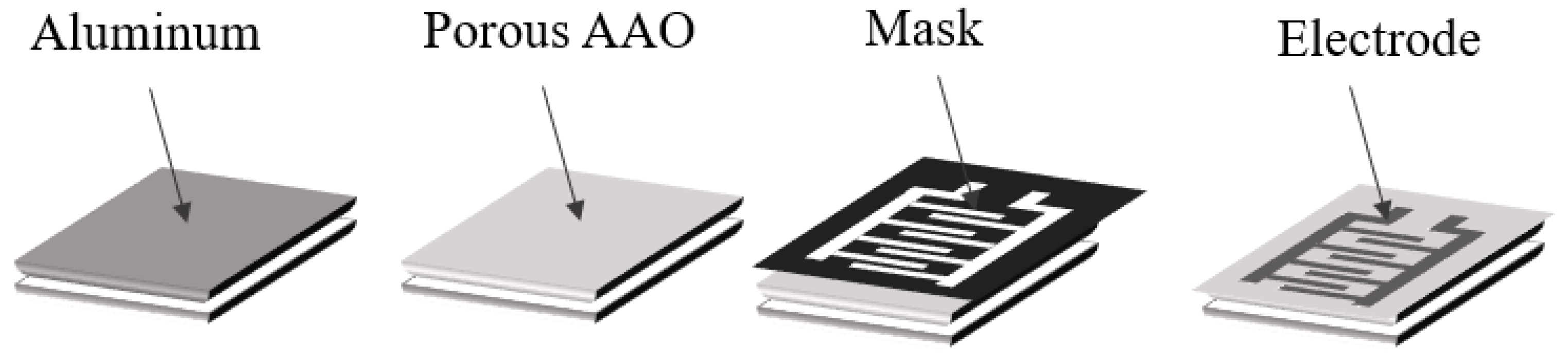
2.2. Anodization
2.3. PVD
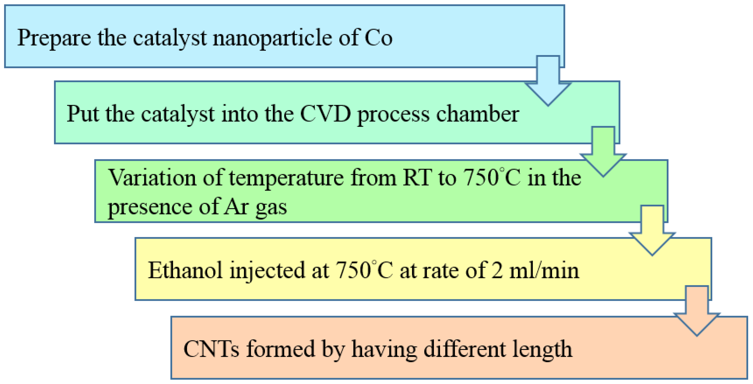
2.4. CVD
3. Humidity Nanosensors
3.1. Ceramic
3.2. Polymers
3.3. Semiconductor
3.4. Carbon-Based
3.5. TENG for Humidity Sensors
3.6. MXene-Based Humidity Sensor
3.7. Summary and Future Applications of Humidity Nanosensors
4. Conclusions
Author Contributions
Funding
Data Availability Statement
Acknowledgments
Conflicts of Interest
References
- Li, Z.; Wang, J.; Xu, Y.; Shen, M.; Duan, C.; Dai, L.; Ni, Y. Green and sustainable cellulose-derived humidity sensors: A review. Carbohydr. Polym. 2021, 270, 118385. [Google Scholar] [CrossRef] [PubMed]
- Anisimov, Y.A.; Evitts, R.W.; Cree, D.E.; Wilson, L.D. Polyaniline/Biopolymer Composite Systems for Humidity Sensor Applications: A Review. Polymers 2021, 13, 2722. [Google Scholar] [CrossRef] [PubMed]
- Barmpakos, D.; Kaltsas, G. A review on humidity, temperature and strain printed sensors—Current trends and future per-spectives. Sensors 2021, 21, 739. [Google Scholar] [CrossRef] [PubMed]
- Duan, Z.; Jiang, Y.; Tai, H. Recent advances in humidity sensors for human body related humidity detection. J. Mater. Chem. C 2021, 9, 14963–14980. [Google Scholar] [CrossRef]
- Mishra, S.; Singh, A.K. Optical sensors for water and humidity and their further applications. Coord. Chem. Rev. 2021, 445, 214063. [Google Scholar] [CrossRef]
- Nakajima, T.; Fujio, Y.; Sugahara, T.; Tsuchiya, T. Flexible Ceramic Film Sensors for Free-Form Devices. Sensors 2022, 22, 1996. [Google Scholar] [CrossRef] [PubMed]
- Blank, T.A.; Eksperiandova, L.P.; Belikov, K.N. Recent trends of ceramic humidity sensors development: A review. Sens. Actuat. B Chem. 2016, 228, 416–442. [Google Scholar] [CrossRef]
- Foucaud, M.; Renka, S.; Klaser, T.; Popović, J.; Skoko, Ž.; Mošner, P.; Noudelkal, L.; Šantić, A. Sodium-Ion Conductivity and Humidity-Sensing Properties of Na2O-MoO3-P2O5 Glass-Ceramics. Nanomaterials 2022, 12, 240. [Google Scholar] [CrossRef]
- Kalyakin, A.S.; Danilov, N.A.; Volkov, A.N. Determining humidity of nitrogen and air atmospheres by means of a protonic ceramic sensor. J. Electroanal. Chem. 2021, 895, 115523. [Google Scholar] [CrossRef]
- Tripathy, A.; Sharma, P.; Pramanik, S.; Silva, F.S.; Bin Abu Osman, N.A. Armalcolite Nanocomposite: A New Paradigm for Flexible Capacitive Humidity Sensor. IEEE Sens. J. 2021, 21, 14685–14692. [Google Scholar] [CrossRef]
- Delipinar, T.; Shafique, A.; Gohar, M.S.; Yapici, M.K. Fabrication and Materials Integration of Flexible Humidity Sensors for Emerging Applications. ACS Omega 2021, 6, 8744–8753. [Google Scholar] [CrossRef] [PubMed]
- Zhao, Y.; Tong, R.-J.; Chen, M.-Q.; Xia, F. Relative humidity sensor based on hollow core fiber filled with GQDs-PVA. Sens. Actuators B Chem. 2018, 284, 96–102. [Google Scholar] [CrossRef]
- Lazarova, K.; Bozhilova, S.; Christova, D.; Babeva, T. Poly(vinyl alcohol)-based thin films for optical humidity sensing. J. Phys. Conf. Ser. 2020, 1492, 012040. [Google Scholar] [CrossRef]
- Lazarova, K.; Bozhilova, S.; Ivanova, S.; Christova, D.; Babeva, T. The Influence of Annealing on Optical and Humidity Sensing Properties of Poly(Vinyl Alcohol-Co-Vinyl Acetal) Thin Films. Proceedings 2019, 42, 16. [Google Scholar] [CrossRef]
- Lazarova, K.; Bozhilova, S.; Novakov, C.; Christova, D.; Babeva, T. Amphiphilic Poly(vinyl Alcohol) Copolymers Designed for Optical Sensor Applications—Synthesis and Properties. Coatings 2020, 10, 460. [Google Scholar] [CrossRef]
- Zhang, J.; DiChiara, A.B.; Novosselov, I.V.; Gao, D.; Chung, J.H. Polyacrylic acid coated carbon nanotube–paper composites for humidity and moisture sensing. J. Mater. Chem. C 2019, 7, 5374–5380. [Google Scholar] [CrossRef]
- Eyebe, G.F.V.A.; Bideau, B.; Loranger, É.; Domingue, F. TEMPO-oxidized cellulose nanofibre (TOCN) films and composites with PVOH as sensitive dielectrics for microwave humidity sensing. Sens. Actuators B Chem. 2019, 291, 385–393. [Google Scholar] [CrossRef]
- Jeong, Y.; Hong, S.; Jung, G.; Shin, W.; Park, J.; Kim, D.; Choi, Y.S.; Bae, J.-H.; Hong, B.H.; Lee, J.-H. Highly stable Si MOSFET-type humidity sensor with ink-jet printed graphene quantum dots sensing layer. Sens. Actuators B Chem. 2021, 343, 130134. [Google Scholar] [CrossRef]
- Yan, M.; Wu, Y.; Hua, Z.; Lu, N.; Sun, W.; Zhang, J.; Fan, S. Humidity compensation based on power-law response for MOS sensors to VOCs. Sens. Actuators B Chem. 2021, 334, 129601. [Google Scholar] [CrossRef]
- Wozniak, L.; Kalinowski, P.; Jasinski, G.; Jasinski, P. FFT analysis of temperature modulated semiconductor gas sensor re-sponse for the prediction of ammonia concentration under humidity interference. Microelectron. Reliab. 2018, 84, 163–169. [Google Scholar] [CrossRef]
- Qi, Q.; Wang, Q.; Liu, N.; Zheng, X.; Ding, X.; Liang, Z.; Wang, Q.; Zhang, G. A Flexible Humidity Sensor Based on Co3O4 Nanoneedles with High Sensitivity and Quick Response. J. Nanoelectron. Optoelectron. 2020, 15, 870–874. [Google Scholar] [CrossRef]
- Farzaneh, A.; Mohammadzadeh, A.; Esrafili, M.D.; Mermer, O. Experimental and theoretical study of TiO2 based nanostructured semiconducting humidity sensor. Ceram. Int. 2019, 45, 8362–8369. [Google Scholar] [CrossRef]
- Wu, Y.; Huang, Q.; Nie, J.; Liang, J.; Joshi, N.; Hayasaka, T.; Zhao, S.; Zhang, M.; Wang, X.; Lin, L. All-Carbon Based Flexible Humidity Sensor. J. Nanosci. Nanotechnol. 2019, 19, 5310–5316. [Google Scholar] [CrossRef] [PubMed]
- Zhou, L.; Wang, M.; Liu, Z.; Guan, J.; Li, T.; Zhang, D. High-performance humidity sensor based on graphitic carbon nitride/polyethylene oxide and construction of sensor array for non-contact humidity detection. Sens. Actuators B Chem. 2021, 344, 130219. [Google Scholar] [CrossRef]
- Ge, W.; Pei, L.; Liu, Y.; Baktur, R. Carbon-nanotube-loaded planar gas and humidity sensor. Microw. Opt. Technol. Lett. 2020, 62, 3857–3863. [Google Scholar] [CrossRef]
- Kim, J.; Cho, J.H.; Lee, H.M.; Hong, S.M. Capacitive Humidity Sensor Based on Carbon Black/Polyimide Composites. Sensors 2021, 21, 1974. [Google Scholar] [CrossRef] [PubMed]
- Epeloa, J.; Repetto, C.E.; Gomez, B.J.A.J.; Nachez, J.L.; Dobry, A. Resistivity humidity sensors based on hydrogenated amorphous carbon films. Mater. Res. Express 2018, 6, 025604. [Google Scholar] [CrossRef]
- Ma, Q.F.; Tou, Z.Q.; Ni, K.; Lim, Y.Y.; Lin, Y.F.; Wang, Y.R.; Zhou, M.H.; Shi, F.F.; Luo, N.; Xin, Y.D.; et al. Carbon-nanotube/Polyvinyl alcohol coated thin core fiber sensor for humidity measurement. Sens. Actuators B Chem. 2018, 257, 800–806. [Google Scholar] [CrossRef]
- Yang, M.-Y.; Huang, M.-L.; Li, Y.-Z.; Feng, Z.-S.; Huang, Y.; Chen, H.-J.; Xu, Z.-Q.; Liu, H.-G.; Wang, Y. Printing assembly of flexible devices with oxidation stable MXene for high performance humidity sensing applications. Sens. Actuators B Chem. 2022, 364, 131867. [Google Scholar] [CrossRef]
- Xing, H.; Li, X.; Lu, Y.; Wu, Y.; He, Y.; Chen, Q.; Liu, Q.; Han, R.P. MXene/MWCNT electronic fabric with enhanced mechanical robustness on humidity sensing for real-time respiration monitoring. Sens. Actuators B Chem. 2022, 361, 131704. [Google Scholar] [CrossRef]
- Ezzat, H.A.; Hegazy, M.A.; Nada, N.A.; Osman, O.; Ibrahim, M.A. Application of natural polymers enhanced with ZnO and CuO as humidity sensor. NRIAG J. Astron. Geophys. 2020, 9, 586–597. [Google Scholar] [CrossRef]
- Tai, H.; Duan, Z.; Wang, Y.; Wang, S.; Jiang, Y. based sensors for gas, humidity, and strain detections: A review. ACS Appl. Mater. Interfaces 2020, 12, 31037–31053. [Google Scholar] [CrossRef]
- Alberti, G.; Zanoni, C.; Losi, V.; Magnaghi, L.; Biesuz, R. Current Trends in Polymer Based Sensors. Chemosensors 2021, 9, 108. [Google Scholar] [CrossRef]
- Sharma, K.; Islam, S.S. Optimization of porous anodic alumina nanostructure for ultra-high sensitive humidity sensor. Sens. Actuators B Chem. 2016, 237, 443–451. [Google Scholar] [CrossRef]
- Balde, M.; Vena, A.; Sorli, B. Fabrication of porous anodic aluminium oxide layers on paper for humidity sensors. Sens. Actuators B Chem. 2015, 220, 829–839. [Google Scholar] [CrossRef]
- Demir, R.; Okur, S.; Şeker, M. Electrical Characterization of CdS Nanoparticles for Humidity Sensing Applications. Ind. Eng. Chem. Res. 2012, 51, 3309–3313. [Google Scholar] [CrossRef]
- Chen, Q.; Nie, M.; Guo, Y. Controlled synthesis and humidity sensing properties of CdS/polyaniline composite based on CdAl layered double hydroxide. Sens. Actuators B Chem. 2018, 254, 30–35. [Google Scholar] [CrossRef]
- Bhattacharjee, M.; Bandyopadhyay, D. Mechanisms of humidity sensing on a CdS nanoparticle coated paper sensor. Sens. Actuators A Phys. 2018, 285, 241–247. [Google Scholar] [CrossRef]
- Huang, G.; Zhou, H.; Wang, C.; Kashi, C.; Ye, X.; Li, W.; Wang, G.; Xu, G. A new 1D inorganic–organic hybrid perovskite-like semiconductor with high stability and humidity response. Inorg. Chem. Commun. 2021, 128, 108581. [Google Scholar] [CrossRef]
- Ke, K.H.; Chung, C.K. High-performance Al/PDMS TENG with novel complex morphology of two-height microneedles array for high-sensitivity force-sensor and self-powered application. Small 2020, 16, 2001209. [Google Scholar] [CrossRef]
- Saqib, Q.M.; Shaukat, R.A.; Khan, M.U.; Chougale, M.; Bae, J. Biowaste Peanut Shell Powder-Based Triboelectric Nano-generator for Biomechanical Energy Scavenging and Sustainably Powering Electronic Supplies. ACS Appl. Electron. Mater. 2020, 2, 3953–3963. [Google Scholar] [CrossRef]
- Shaukat, R.A.; Saqib, Q.M.; Khan, M.U.; Chougale, M.Y.; Bae, J. Bio-waste sunflower husks powder based recycled triboelectric nanogenerator for energy harvesting. Energy Rep. 2021, 7, 724–731. [Google Scholar] [CrossRef]
- Ren, Z.; Ding, Y.; Nie, J.; Wang, F.; Xu, L.; Lin, S.; Chen, X.; Wang, Z.L. Environmental energy harvesting adapting to different weather conditions and self-powered vapor sensor based on humidity-responsive triboelectric nanogenerators. ACS Appl. Mater. Interfaces 2019, 11, 6143–6153. [Google Scholar] [CrossRef]
- Farahani, E.; Mohammadpour, R. Fabrication of flexible self-powered humidity sensor based on super-hydrophilic titanium oxide nanotube arrays. Sci. Rep. 2020, 10, 13032. [Google Scholar] [CrossRef] [PubMed]
- Zhang, Y.; Han, P.; Zhou, H.; Wu, N.; Wei, Y.; Yao, X.; Zhou, J.; Song, Y. Highly brilliant noniridescent structural colors ena-bled by graphene nanosheets containing graphene quantum dots. Adv. Funct. Mater. 2018, 28, 1802585. [Google Scholar] [CrossRef]
- Hou, A.; Chen, H.; Zheng, C.; Xie, K.; Gao, A. Assembly of a Fluorescent Chiral Photonic Crystal Membrane and Its Sensitive Responses to Multiple Signals Induced by Small Molecules. ACS Nano 2020, 14, 7380–7388. [Google Scholar] [CrossRef] [PubMed]
- Yu, L.; Xu, H.; Monro, T.M.; Lancaster, D.G.; Xie, Y.; Zeng, H.; Chen, G.Y.; Liu, X. Ultrafast colorimetric humidity-sensitive polyelectrolyte coating for touchless control. Mater. Horiz. 2016, 4, 72–82. [Google Scholar] [CrossRef]
- Chung, C.K.; Ku, C.A. Effect of Humidity on Nanoporous Anodic Alumina Oxide (AAO). World J. Nanosci. Nanotech. 2018, 1, 1003. [Google Scholar]
- Rao, X.; Zhao, L.; Xu, L.; Wang, Y.; Liu, K.; Wang, Y.; Chen, G.Y.; Liu, T.; Wang, Y. Review of Optical Humidity Sensors. Sensors 2021, 21, 8049. [Google Scholar] [CrossRef]
- Momtaz, M.; Chen, J. High-Performance Colorimetric Humidity Sensors Based on Konjac Glucomannan. ACS Appl. Mater. Interfaces 2020, 12, 54104–54116. [Google Scholar] [CrossRef]
- Andika, R.; Aziz, F.; Ahmad, Z.; Doris, M.; Fauzia, V.; Bawazeer, T.M.; Alsenany, N.; Alsoufi, M.S.; Supangat, A. Organic nanostructure sensing layer developed by AAO template for the application in humidity sensors. J. Mater. Sci. Mater. Electron. 2018, 30, 2382–2388. [Google Scholar] [CrossRef]
- Li, X.; Chen, X.; Chen, X.; Ding, X.; Zhao, X. High-sensitive humidity sensor based on graphene oxide with evenly dispersed multiwalled carbon nanotubes. Mater. Chem. Phys. 2018, 207, 135–140. [Google Scholar] [CrossRef]
- Zhu, P.; Ou, H.; Kuang, Y.; Hao, L.; Diao, J.; Chen, G. Cellulose Nanofiber/Carbon Nanotube Dual Network-Enabled Humidity Sensor with High Sensitivity and Durability. ACS Appl. Mater. Interfaces 2020, 12, 33229–33238. [Google Scholar] [CrossRef]
- Zhang, D.; Xu, Z.; Yang, Z.; Song, X. High-performance flexible self-powered tin disulfide nanoflowers/reduced graphene oxide nanohybrid-based humidity sensor driven by triboelectric nanogenerator. Nano Energy 2019, 67, 104251. [Google Scholar] [CrossRef]
- Yang, C.C.; Liu, T.H.; Chang, S.H. Relative humidity sensing properties of indium nitride compound with oxygen doping on silicon and AAO substrates. Mod. Phys. Lett. B 2019, 33, 1940044. [Google Scholar] [CrossRef]
- Chung, C.K.; Khor, O.K.; Kuo, E.H.; Ku, C.A. Total effective surface area principle for enhancement of capacitive humidity sensor of thick-film nanoporous alumina. Mater. Lett. 2020, 260, 126921. [Google Scholar] [CrossRef]
- Chung, C.-K.; Liu, T.Y.; Chang, W.T. Effect of oxalic acid concentration on the formation of anodic aluminum oxide using pulse anodization at room temperature. Microsyst. Technol. 2009, 16, 1451–1456. [Google Scholar] [CrossRef]
- Chung, C.; Tsai, C.; Hsu, C.; Kuo, E.; Chen, Y.; Chung, I. Impurity and temperature enhanced growth behaviour of anodic aluminium oxide from AA5052 Al-Mg alloy using hybrid pulse anodization at room temperature. Corros. Sci. 2017, 125, 40–47. [Google Scholar] [CrossRef]
- Chung, C.; Ku, C.; Wu, Z. A high-and-rapid-response capacitive humidity sensor of nanoporous anodic alumina by one-step anodizing commercial 1050 aluminum alloy and its enhancement mechanism. Sens. Actuators B Chem. 2021, 343, 130156. [Google Scholar] [CrossRef]
- Manut, A.; Zoolfakar, A.S.; Mamat, M.H.; Ab Ghani, N.S.; Zolkapli, M. Characterization of Titanium Dioxide (TiO2) Nanotubes for Resistive-type Humidity Sensor. In Proceedings of the IEEE International Conference on Semiconductor Electronics (ICSE), Kuala Lumpur, Malaysia, 28–29 July 2020; pp. 104–107. [Google Scholar]
- Wu, Z.; Richter, C.; Menon, L. A Study of Anodization Process during Pore Formation in Nanoporous Alumina Templates. J. Electrochem. Soc. 2007, 154, E8. [Google Scholar] [CrossRef]
- Liu, S.; Tian, J.; Zhang, W. Fabrication and application of nanoporous anodic aluminum oxide: A review. Nanotechnology 2021, 32, 222001. [Google Scholar] [CrossRef] [PubMed]
- Chung, C.K.; Khor, O.K.; Syu, C.J.; Chen, S.W. Effect of oxalic acid concentration on the magnetically enhanced capacitance and resistance of AAO humidity sensor. Sens. Actuators B Chem. 2015, 210, 69–74. [Google Scholar] [CrossRef]
- Akram, R.; Saleem, M.; Farooq, Z.; Yaseen, M.; Almohaimeed, Z.M.; Zafar, Q. Integrated Capacitive-and Resistive-Type Bimodal Relative Humidity Sensor Based on 5, 10, 15, 20-Tetraphenylporphyrinatonickel (II) (TPPNi) and Zinc Oxide (ZnO) Nanocomposite. ACS Omega 2022, 7, 30590–30600. [Google Scholar] [CrossRef] [PubMed]
- Kim, Y.; Jung, B.; Lee, H.; Kim, H.; Lee, K.; Park, H. Capacitive humidity sensor design based on anodic aluminum oxide. Sens. Actuators B Chem. 2009, 141, 441–446. [Google Scholar] [CrossRef]
- Yang, J.; Shi, R.; Lou, Z.; Chai, R.; Jiang, K.; Shen, G. Flexible Smart Noncontact Control Systems with Ultrasensitive Humidity Sensors. Small 2019, 15, 1902801. [Google Scholar] [CrossRef]
- Yan, X.; Li, C.; Zhao, L.; Tian, S.; Zhang, Z.; Li, M.; Li, H.; Qian, L.; Gong, X.; Huang, Y.; et al. Surface acoustic wave relative humidity sensor based on sputtering SiO2 film. Surf. Interface Anal. 2021, 53, 867–875. [Google Scholar] [CrossRef]
- Kunchakara, S.; Ratan, A.; Dutt, M.; Shah, J.; Kotnala, R.; Singh, V. Impedimetric humidity sensing studies of Ag doped MCM-41 mesoporous silica coated on silver sputtered interdigitated electrodes. J. Phys. Chem. Solids 2020, 145, 109531. [Google Scholar] [CrossRef]
- Frydrysiak, M. Comparison of Textile Resistive Humidity Sensors Made by Sputtering, Printing and Embroidery Techniques. Fibres Text. East. Eur. 2020, 28, 91–96. [Google Scholar] [CrossRef]
- Kumar, N.; Evaristo, M.; Trindade, B.; Faia, P. Humidity sensing properties of thin silicon-tin films prepared by magnetron sputtering. Sens. Actuators B Chem. 2020, 321, 128554. [Google Scholar] [CrossRef]
- Xu, Z.; Li, Z. Design and fabrication of ZnO-based SAW sensor using low power homo-buffer layer for enhanced humidity sensing. IEEE Sens. J. 2021, 21, 7428–7433. [Google Scholar] [CrossRef]
- Jeong, W.; Song, J.; Bae, J.; Nandanapalli, K.R.; Lee, S. Breathable Nanomesh Humidity Sensor for Real-Time Skin Humidity Monitoring. ACS Appl. Mater. Interfaces 2019, 11, 44758–44763. [Google Scholar] [CrossRef]
- Kundu, S.; Majumder, R.; Roy, S.; Chowdhury, M.P. Electro-polymerization of polyaniline on CVD grown transferrable vertically aligned CNT forest and its application in resistive detection of relative humidity. Mater. Today Proc. 2021, 43, 3591–3594. [Google Scholar] [CrossRef]
- Liang, R.; Luo, A.; Zhang, Z.; Li, Z.; Han, C.; Wu, W. Research Progress of Graphene-Based Flexible Humidity Sensor. Sensors 2020, 20, 5601. [Google Scholar] [CrossRef] [PubMed]
- Singh, E.; Kumar, U.; Srivastava, R.; Yadav, B.C. Catalytic growth of MWCNT using CVD and its application as opto-electronic humidity sensor. Carbon Lett. 2019, 30, 215–224. [Google Scholar] [CrossRef]
- Nahar, R. Study of the performance degradation of thin film aluminum oxide sensor at high humidity. Sens. Actuators B Chem. 2000, 63, 49–54. [Google Scholar] [CrossRef]
- Chen, S.; Khor, O.; Liao, M.; Chung, C. Sensitivity evolution and enhancement mechanism of porous anodic aluminum oxide humidity sensor using magnetic field. Sens. Actuators B Chem. 2014, 199, 384–388. [Google Scholar] [CrossRef]
- Fernandez, F.D.M.; Bissannagari, M.; Kim, J. Fully inkjet-printed BaTiO3 capacitive humidity sensor: Microstructural engineering of the humidity sensing layer using bimodal ink. Ceram. Int. 2021, 47, 24693–24698. [Google Scholar] [CrossRef]
- Ertug, B. Electrical Conductivity and Hysteresis Characteristic of BaTiO3-Based Sensors with Polymethyl metacrylate (PMMA) Pore Former. Sens. Mater. 2013, 25, 309–321. [Google Scholar]
- Tsai, F.-S.; Wang, S.-J. Enhanced sensing performance of relative humidity sensors using laterally grown ZnO nanosheets. Sensors Actuators B Chem. 2014, 193, 280–287. [Google Scholar] [CrossRef]
- Mahapatra, P.L.; Mondal, P.P.; Das, S.; Saha, D. Novel capacitive humidity sensing properties of cobalt chromite nanoparticles based thick film. Microchem. J. 2020, 152, 104452. [Google Scholar] [CrossRef]
- Lazarova, K.; Bozhilova, S.; Ivanova, S.; Christova, D.; Babeva, T. Flexible and Transparent Polymer-Based Optical Humidity Sensor. Sensors 2021, 21, 3674. [Google Scholar] [CrossRef] [PubMed]
- Najeeb, M.A.; Ahmad, Z.; Shakoor, R.A. Organic thin-film capacitive and resistive humidity sensors: A focus review. Adv. Mater. Interfaces 2018, 5, 1800969. [Google Scholar] [CrossRef]
- Sahoo, K.; Mohanty, B.; Biswas, A.; Nayak, J. Role of hexamethylenetetramine in ZnO-cellulose nanocomposite enabled UV and humidity sensor. Mater. Sci. Semicond. Process. 2020, 105, 104699. [Google Scholar] [CrossRef]
- Kalim, B.; Ansar, M.T.; Ullah, Z.; Abbas, S.K.; Riaz, S.; Siddiqi, S.A.; Atiq, S. CNTs/ZnO and CNTs/ZnO/Ag multilayers spray coated on cellulose fiber for use as an efficient humidity sensor. Ceram. Int. 2020, 46, 25593–25597. [Google Scholar] [CrossRef]
- Khalifa, M.; Wuzella, G.; Lammer, H.; Mahendran, A.R. Smart paper from graphene coated cellulose for high-performance humidity and piezoresistive force sensor. Synth. Met. 2020, 266, 116420. [Google Scholar] [CrossRef]
- Syrový, T.; Maronová, S.; Kuberský, P.; Ehman, N.V.; Vallejos, M.E.; Pretl, S.; Felissia, F.E.; Area, M.C.; Chinga-Carrasco, G. Wide range humidity sensors printed on biocomposite films of cellulose nanofibril and poly (ethylene glycol). J. Appl. Polym. Science. 2019, 136, 47920. [Google Scholar] [CrossRef]
- Alrammouz, R.; Podlecki, J.; Vena, A.; Garcia, R.; Abboud, P.; Habchi, R.; Sorli, B. Highly porous and flexible capacitive hu-midity sensor based on self-assembled graphene oxide sheets on a paper substrate. Sens. Actuators B Chem. 2019, 298, 126892. [Google Scholar] [CrossRef]
- Meng, Y.; Cao, Y.; Ji, H.; Chen, J.; He, Z.; Long, Z.; Dong, C. Fabrication of environmental humidity-responsive iridescent films with cellulose nanocrystal/polyols. Carbohydr. Polym. 2020, 240, 116281. [Google Scholar] [CrossRef]
- Li, J.; Zhang, J.; Sun, H.; Yang, Y.; Ye, Y.; Cui, J.; He, W.; Yong, X.; Xie, Y. An optical fiber sensor based on carboxymethyl cellulose/carbon nanotubes composite film for simultaneous measurement of relative humidity and temperature. Opt. Commun. 2020, 467, 125740. [Google Scholar] [CrossRef]
- Wawrzynek, E.; Baumbauer, C.; Arias, A.C. Characterization and Comparison of Biodegradable Printed Capacitive Humidity Sensors. Sensors. 2021, 21, 6557. [Google Scholar] [CrossRef]
- Xiao, X.; Zhang, Q.J.; He, J.H.; Xu, Q.F.; Li, H.; Li, N.J.; Chen, D.Y.; Lu, J.M. Polysquaraines: Novel humidity sensor ma-terials with ultra-high sensitivity and good reversibility. Sens. Actuators B Chem. 2018, 255, 1147–1152. [Google Scholar] [CrossRef]
- Fernandes, L.; Correia, D.M.; Pereira, N.; Tubio, C.; Lanceros-Mendez, S. Highly Sensitive Humidity Sensor Based on Ionic Liquid–Polymer Composites. ACS Appl. Polym. Mater. 2019, 1, 2723–2730. [Google Scholar] [CrossRef]
- Hamouche, H.; Makhlouf, S.; Chaouchi, A.; Laghrouche, M. Humidity Sensor Based on Keratin bio Polymer Film. Sens. Actuators A Phys. 2018, 282, 132–141. [Google Scholar] [CrossRef]
- Zhou, C.; Zhang, X.; Tang, N.; Fang, Y.; Zhang, H.; Duan, X. Rapid response flexible humidity sensor for respiration monitoring using nano-confined strategy. Nanotechnology 2020, 31, 125302. [Google Scholar] [CrossRef] [PubMed]
- Likhite, R.; Banerjee, A.; Majumder, A.; Karkhanis, M.; Kim, H.; Mastrangelo, C.H. Parametrically Amplified Low-Power MEMS Capacitive Humidity Sensor. Sensors 2019, 19, 3954. [Google Scholar] [CrossRef]
- Dai, J.; Zhao, H.; Lin, X.; Liu, S.; Fei, T.; Zhang, T. Design strategy for ultrafast-response humidity sensors based on gel poly-mer electrolytes and application for detecting respiration. Sens. Actuators B Chem. 2020, 304, 127270. [Google Scholar] [CrossRef]
- Yao, K.; Meng, Q.; Bulone, V.; Zhou, Q. Flexible and Responsive Chiral Nematic Cellulose Nanocrystal/Poly(ethylene glycol) Composite Films with Uniform and Tunable Structural Color. Adv. Mater. 2017, 29, 1701323. [Google Scholar] [CrossRef]
- Sun, L.; Wang, B.; Wang, Y. A Novel Silicon Carbide Nanosheet for High-Performance Humidity Sensor. Adv. Mater. Interfaces 2018, 5, 1701300. [Google Scholar] [CrossRef]
- Traversa, E.; Gnappi, G.; Montenero, A.; Gusmano, G. Ceramic thin films by sol-gel processing as novel materials for integrated humidity sensors. Sens. Actuators B Chem. 1996, 31, 59–70. [Google Scholar] [CrossRef]
- Chen, Z.; Lu, C. Humidity Sensors: A Review of Materials and Mechanisms. Sens. Lett. 2005, 3, 274–295. [Google Scholar] [CrossRef]
- Zhang, D.; Chang, H.; Li, P.; Liu, R.; Xue, Q. Fabrication and characterization of an ultrasensitive humidity sensor based on metal oxide/graphene hybrid nanocomposite. Sens. Actuators B Chem. 2016, 225, 233–240. [Google Scholar] [CrossRef]
- An, H.; Habib, T.; Shah, S.; Gao, H.; Patel, A.; Echols, I.; Zhao, X.; Radovic, M.; Green, M.J.; Lutkenhaus, J.L. Water Sorption in MXene/Polyelectrolyte Multilayers for Ultrafast Humidity Sensing. ACS Appl. Nano Mater. 2019, 2, 948–955. [Google Scholar] [CrossRef]
- Li, N.; Jiang, Y.; Zhou, C.; Xiao, Y.; Meng, B.; Wang, Z.; Huang, D.; Xing, C.; Peng, Z. High-performance humidity sensor based on urchin-like composite of Ti3C2 MXene-derived TiO2 nanowires. ACS Appl. Mater. Interfaces 2019, 11, 38116–38125. [Google Scholar] [CrossRef] [PubMed]
- Lu, J.; Liang, K.; Xu, C.; Wang, X.; Ouyang, H.; Huang, J.; Feng, L. Humidity sensor based on heterogeneous CoTiO3/TiO2 film with vertically aligned nanocrystalline structure. Vacuum 2019, 163, 292–300. [Google Scholar] [CrossRef]
- Kumar, U.; Yang, Y.-H.; Deng, Z.-Y.; Lee, M.-W.; Huang, W.-M.; Wu, C.-H. In situ growth of ternary metal sulfide based quantum dots to detect dual gas at extremely low levels with theoretical investigations. Sens. Actuators B Chem. 2021, 353, 131192. [Google Scholar] [CrossRef]
- Tang, H.; Li, Y.; Ye, H.; Hu, F.; Gao, C.; Tao, L.; Tu, T.; Gou, G.; Zhang, G. High-performance humidity sensor using Schottky-contacted SnS nanoflakes for noncontact healthcare monitoring. Nanotechnology 2019, 31, 055501. [Google Scholar] [CrossRef]
- Rambabu, A.; Singh, D.K.; Pant, R.; Nanda, K.K.; Krupanidhi, S.B. Self-powered, ultrasensitive, room temperature humidity sensors using SnS2 nanofilms. Sci. Rep. 2020, 10, 14611. [Google Scholar] [CrossRef]
- Maurya, D.K.; Sikarwar, S.; Chaudhary, P.; Angaiah, S.; Yadav, B.C. Synthesis and Characterization of Nanostructured Copper Zinc Tin Sulphide (CZTS) for Humidity Sensing Applications. IEEE Sens. J. 2019, 19, 2837–2846. [Google Scholar] [CrossRef]
- Patil, U.; Dhanasekar, M.; Kadrekar, R.; Arya, A.; Bhat, S.V.; Late, D.J. Efficient humidity sensor based on surfactant free Cu2ZnSnS4 nanoparticles. Ceram. Int. 2022, 48, 28898–28905. [Google Scholar] [CrossRef]
- Chaudhary, P.; Maurya, D.K.; Pandey, A.; Verma, A.; Tripathi, R.K.; Kumar, S.; Yadav, B. Design and development of flexible humidity sensor for baby diaper alarm: Experimental and theoretical study. Sens. Actuators B Chem. 2021, 350, 130818. [Google Scholar] [CrossRef]
- Han, J.-W.; Kim, B.; Li, J.; Meyyappan, M. Carbon Nanotube Based Humidity Sensor on Cellulose Paper. J. Phys. Chem. C 2012, 116, 22094–22097. [Google Scholar] [CrossRef]
- Xie, L.; Feng, Y.; Mäntysalo, M.; Chen, Q.; Zheng, L.R. Integration of f-MWCNT sensor and printed circuits on paper substrate. IEEE Sens. J. 2013, 13, 3948–3956. [Google Scholar] [CrossRef]
- Steffens, C.; Manzoli, A.; Paschoalin, R.T.; Tiggemann, L.; Steffens, J.; Teixeira, E.; Herrmann, P.S.D.P. Tracing paper substrate used for development of interdigitated graphite electrode and its application as humidity sensor. Synth. Met. 2013, 183, 36–39. [Google Scholar] [CrossRef]
- Zhao, H.; Zhang, T.; Qi, R.; Dai, J.; Liu, S.; Fei, T. Drawn on paper: A reproducible humidity sensitive device by handwriting. ACS Appl. Mater. Interfaces 2017, 9, 28002–28009. [Google Scholar] [CrossRef]
- Bi, H.; Yin, K.; Xie, X.; Ji, J.; Wan, S.; Sun, L.; Terrones, M.; Dresselhaus, M.S. Ultrahigh humidity sensitivity of graphene oxide. Sci. Rep. 2013, 3, 2714. [Google Scholar] [CrossRef]
- Anju, V.P.; Jithesh, P.R.; Narayanankutty, S.K. A novel humidity and ammonia sensor based on nanofibers/polyaniline/polyvinyl alcohol. Sens. Actuators A Phys. 2019, 285, 35–44. [Google Scholar] [CrossRef]
- Peng, Y.; Zhao, Y.; Chen, M.-Q.; Xia, F. Research Advances in Microfiber Humidity Sensors. Small 2018, 14, e1800524. [Google Scholar] [CrossRef] [PubMed]
- Han, Y.-G. Relative Humidity Sensors Based on Microfiber Knot Resonators—A Review. Sensors 2019, 19, 5196. [Google Scholar] [CrossRef] [PubMed]
- Xu, K.; Li, H.; Liu, Y.; Wang, Y.; Tian, J.; Wang, L.; Du, J.; He, Z.; Song, A. Optical fiber humidity sensor based on water ab-sorption peak near 2-µm waveband. IEEE Photon. J. 2019, 11, 7101308. [Google Scholar] [CrossRef]
- Azzuhri, S.; Amiri, I.; Zulkhairi, A.; Salim, M.; Razak, M.; Khyasudeen, M.; Ahmad, H.; Zakaria, R.; Yupapin, P. Application of graphene oxide based Microfiber-Knot resonator for relative humidity sensing. Results Phys. 2018, 9, 1572–1577. [Google Scholar] [CrossRef]
- Le, A.D.D.; Han, Y.G. Relative humidity sensor based on a few-mode microfiber knot resonator by mitigating the group index difference of a few-mode microfiber. J. Light. Technol. 2018, 36, 904–909. [Google Scholar] [CrossRef]
- Yusoff, S.; Lim, C.; Azzuhri, S.; Ahmad, H.; Zakaria, R. Studies of Ag/TiO2 plasmonics structures integrated in side polished optical fiber used as humidity sensor. Results Phys. 2018, 10, 308–316. [Google Scholar] [CrossRef]
- Xu, K.; Du, G.; Zhong, T.; Chen, D.; Lin, X.; Zheng, Z.; Wang, S. Green sustainable, facile nitrogen self-doped porous carbon derived from chitosan/cellulose nanocrystal biocomposites as a potential anode material for lithium-ion batteries. J. Taiwan Inst. Chem. Eng. 2020, 109, 79–89. [Google Scholar] [CrossRef]
- Chung, C.; Ke, K. High contact surface area enhanced Al/PDMS triboelectric nanogenerator using novel overlapped microneedle arrays and its application to lighting and self-powered devices. Appl. Surf. Sci. 2020, 508, 145310. [Google Scholar] [CrossRef]
- Dong, B.; Zhang, Z.; Shi, Q.; Wei, J.; Ma, Y.; Xiao, Z.; Lee, C. Biometrics-protected optical communication enabled by deep learning–enhanced triboelectric/photonic synergistic interface. Sci. Adv. 2022, 8, eabl9874. [Google Scholar] [CrossRef] [PubMed]
- Trinh, V.L.; Chung, C.K. A Facile Method and Novel Mechanism Using Microneedle-Structured PDMS for Triboelectric Gen-erator Applications. Small 2017, 13, 1700373. [Google Scholar] [CrossRef] [PubMed]
- Trinh, V.L.; Chung, C.K. Harvesting mechanical energy, storage, and lighting using a novel PDMS based triboelectric generator with inclined wall arrays and micro-topping structure. Appl. Energy 2018, 213, 353–365. [Google Scholar] [CrossRef]
- Ke, K.-H.; Lin, L.; Chung, C.-K. Low-cost micro-graphite doped polydimethylsiloxane composite film for enhancement of mechanical-to-electrical energy conversion with aluminum and its application. J. Taiwan Inst. Chem. Eng. 2022, 135, 104388. [Google Scholar] [CrossRef]
- Lin, L.; Chung, C.K. PDMS Microfabrication and Design for Microfluidics and Sustainable Energy Application. Micromachines 2021, 12, 1350. [Google Scholar] [CrossRef]
- Wang, D.; Zhang, D.; Li, P.; Yang, Z.; Mi, Q.; Yu, L. Electrospinning of flexible poly (vinyl alcohol)/MXene nanofiber-based humidity sensor self-powered by monolayer molybdenum diselenide piezoelectric nanogenerator. Nano-Micro Lett. 2021, 13, 57. [Google Scholar] [CrossRef]
- Naguib, M.; Kurtoglu, M.; Presser, V.; Lu, J.; Niu, J.; Heon, M.; Hultman, L.; Gogotsi, Y.; Barsoum, M.W. Two-Dimensional Nanocrystals Produced by Exfoliation of Ti3AlC2. Adv. Mater. 2011, 23, 4248–4253. [Google Scholar] [CrossRef] [PubMed]
- Haq, Y.-U.; Ullah, R.; Mazhar, S.; Khattak, R.; Qarni, A.A.; Haq, Z.-U.; Amin, S. Synthesis and characterization of 2D MXene: Device fabrication for humidity sensing. J. Sci. Adv. Mater. Devices 2021, 7, 100390. [Google Scholar] [CrossRef]
- Han, M.; Shen, W. Nacre-inspired cellulose nanofiber/MXene flexible composite film with mechanical robustness for humidity sensing. Carbohydr. Polym. 2022, 298, 120109. [Google Scholar] [CrossRef] [PubMed]
- Wang, Y.; Hu, C.; Li, Z.; Zheng, D.; Cui, F.; Yang, X. Theoretical and Simulation Analysis of Static and Dynamic Properties of MXene-Based Humidity Sensors. Appl. Sci. 2022, 12, 8254. [Google Scholar] [CrossRef]
- Chung, C.-K.; Huang, Y.-J.; Wang, T.-K.; Lo, Y.-L. Fiber-Based Triboelectric Nanogenerator for Mechanical Energy Harvesting and Its Application to a Human–Machine Interface. Sensors 2022, 22, 9632. [Google Scholar] [CrossRef]


| Sensing Material | Measurement Type | RH Range (% RH) | Response/Sensitivity | Response and Recovery Time | Refs |
|---|---|---|---|---|---|
| CaMgFe1.33Ti3O12 | Capacitance | 33–95 | ~708% (response) | 8.53/11.25 s | [10] |
| Spin coating polymer material on AAO | Capacitance | 20–90 | ~280% (response) | NA | [51] |
| AAO on Si | Capacitance | 30–90 | ~4.4% (response) | 289/286 s | [55] |
| AAO | Capacitance | 15–80 | 8000% (response) | 45/36 s | [56] |
| AAO | Capacitance | 20–80 | 5013% (response) | 8/9 s | [59] |
| BaTiO3 ink | Capacitance | 20–80 | 575 nF/% RH | 37/15 s | [78] |
| BaTiO3-PMMA composite | Capacitance | 30–98 | 1.9pF/%RH | 120/60 s | [79] |
| ZnO nanosheet | Resistance | 12–96 | 220% (response) | 600/3 s | [80] |
| CoCr2O4 | Capacitance | 0–95 | ~350% (response) | NA | [81] |
| Sensing Material | Substrate | Refs |
|---|---|---|
| AAO | Paper | [35] |
| amphiphilic copolymer poly (vinyl alcohol) | PET | [82] |
| ZnO-cellulose | Cellulose | [84] |
| CNTs/ZnO/Ag/cellulosic paper | Cellulose | [85] |
| Graphene-coated cellulosic paper | Cellulose | [86] |
| CNF with polyethylene glycol (PEG) | Cellulose nanofibers (CNF) | [87] |
| GO-coated cellulosic paper | Cellulose | [88] |
| CNC/polyol | Cellulose nanocrystals (CNC) | [89] |
| CMC/CNTs | Carboxymethyl cellulose (CMC) | [90] |
| PET | PET | [91] |
| Sensing Material | Measurement Type | RH Range (% RH) | Response/Sensitivity | Response and Recovery Time | Refs |
|---|---|---|---|---|---|
| polysquaraine | Impedance | 33–95 | NA | 3/16 s | [92] |
| FeCl4/PVDF composite | Resistance | 35–90 | 75% | About 120/180 s | [93] |
| Keratin bio-composite polymer | Capacitance | 16–82 | 855.66% | 30/51 s | [94] |
| PEDOT/PSS | Resistance | 0–28.4 | 13% | 0.63/2.05 s | [95] |
| polyimide | Capacitance | 25–85 | 16% | NA | [96] |
| MPOSS-PIL | Impedance | 11–95 | NA | 0.19/0.3 s | [97] |
| Sensing Material | Measurement Type | Wavelength/Intensity Change | Refs |
|---|---|---|---|
| poly(styrene-methyl-methacrylate-acrylic acid)/graphene | Reflective spectrum | About 101 nm | [45] |
| cellulose nanocrystals/poly(ethylene glycol)/[N-(3-N-benzyl-N,N-dimethylpropyl ammonium chloride)-1,8-naphthalimide]hydrazine | Reflection spectrum | About 164 nm | [46] |
| poly(diallyldimethylammonium)/poly(styrenesulfonate) polyelectrolyte multilayer | Reflection spectrum | About 129 nm | [47] |
| konjac glucomannan | Reflection spectrum | About 385 nm | [50] |
| poly (vinyl alcohol) on PET | Transmission spectrum | About 15% transmission intensity | [82] |
| cellulose nanocrystals/poly(ethylene glycol) | Reflection spectrum | About 172 nm | [98] |
| Sensing Material | Measurement Type | RH Range (% RH) | Response/Sensitivity | Response and Recovery Time | Refs |
|---|---|---|---|---|---|
| CdS | Resistive | 17–85% | NA | ~60 s | [36] |
| CdS/Polyaniline | Resistive | 11–95% | NA | ~8 s | [37] |
| CdS | Resistive | 5–99% | ~60% (response) | ~55 s (normal)~3 s (forced) | [38] |
| SnS nanoflake | Current | 3–99% | 2,491,000% (response) | 6/4 s | [107] |
| SnS2 | Resistive | 2–99% | 154,000% (response) | 13.2/0.87 s | [108] |
| CZTS | Resistive | 10–90% | 10.77 MΩ/%RH | 7.4/58.1 s | [109] |
| [(Me3)DAB(Me3)] PbI4·H2O | Current | 10–100% | ~1,000,000% (response) | NA | [39] |
| SnO2/grapheme oxide | Capacitance | 11–97% | 1604.89 pF/%RH (sensitivity) | 102/6 s | [102] |
| T3C2/polyelectrolyte | Resistive | 10−70% | 1600% (response) | 110/220 ms | [103] |
| Ti3C2/TiO2 Composite | Capacitance | 7−97% | 1614 pF/% RH | 0.5/2 s | [104] |
| CoTiO3/TiO2 Composite | Resistive | 11–95% | 15,723% (response) | NA | [105] |
| Sensing Material | Measurement Type | RH Range (% RH) | Response/Sensitivity | Response and Recovery Time | Refs |
|---|---|---|---|---|---|
| Graphitic carbon nitride | Impedance | 11−97 | 9,756,300% (response) | 2.2/3 s | [24] |
| GO/MWCNT | Capacitance | 11−97 | 7980 pF/% RH (sensitivity) | 5/2.5 s | [52] |
| CNF/CNT | Current | 11−95 | 65% (response) | 321/435 s | [53] |
| Graphene oxide sheets | Capacitance | 30−90 | 5.65 fF/% RH (sensitivity) | NA | [88] |
| SWCNT | Conductance | 10−90 | 37.5% (response) | 6/200 s (10−60% RH) | [112] |
| MWCNT | Conductance | 20−90 | 61.0% (response) | NA | [113] |
| Graphite | Voltage | 20−70 | 215% (response) | 6/8 min | [114] |
| GO/MWCNT | Current | 11−95 | 33% (response) | 470/500 s | [115] |
| Graphene oxide | Capacitance | 15−95 | 35,000 pF/% RH (sensitivity) | 10.5/41 s | [116] |
| Carbon nanofiber (CNF) | Capacitance | 40−100 | 3500 % | 41/50 s | [117] |
| Sensing Method | Sensitive Material | Sensitivity | Refs |
|---|---|---|---|
| Silica MKRs | MWCNT | 1.10 µW/%RH | [75] |
| Silica MKRs | Silica | 0.034 dB/% RH (power) | [120] |
| Silica MKRs | Graphene Oxide | 0.0104 nm/% RH | [121] |
| Silica MKRs | Polyvinyl Alcohol (PVA) | −1.53 nm/% RH | [122] |
| MKRs | Ag/TiO2 | 13.4 mW/% RH | [123] |
| Sensing Material | Measurement Type | RH Range (% RH) | Response | Response and Recovery Time | Refs |
|---|---|---|---|---|---|
| Peanut shell powder (PSP)-based TENG | Voltage | 41.5–74.7 | About 65% | NA | [41] |
| Sunflower husk powder based TENG | Voltage | 37–89 | About 200% | NA | [42] |
| TiO2 based TENG | Voltage | 20–84 | 320% | NA | [44] |
| Poly(vinyl alcohol)/MXene Nanofber TENG | Voltage | 11–97 | 4000% | 0.9/6.3 s | [131] |
Disclaimer/Publisher’s Note: The statements, opinions and data contained in all publications are solely those of the individual author(s) and contributor(s) and not of MDPI and/or the editor(s). MDPI and/or the editor(s) disclaim responsibility for any injury to people or property resulting from any ideas, methods, instructions or products referred to in the content. |
© 2023 by the authors. Licensee MDPI, Basel, Switzerland. This article is an open access article distributed under the terms and conditions of the Creative Commons Attribution (CC BY) license (https://creativecommons.org/licenses/by/4.0/).
Share and Cite
Ku, C.-A.; Chung, C.-K. Advances in Humidity Nanosensors and Their Application: Review. Sensors 2023, 23, 2328. https://doi.org/10.3390/s23042328
Ku C-A, Chung C-K. Advances in Humidity Nanosensors and Their Application: Review. Sensors. 2023; 23(4):2328. https://doi.org/10.3390/s23042328
Chicago/Turabian StyleKu, Chin-An, and Chen-Kuei Chung. 2023. "Advances in Humidity Nanosensors and Their Application: Review" Sensors 23, no. 4: 2328. https://doi.org/10.3390/s23042328
APA StyleKu, C.-A., & Chung, C.-K. (2023). Advances in Humidity Nanosensors and Their Application: Review. Sensors, 23(4), 2328. https://doi.org/10.3390/s23042328