1. Introduction
Different industries often use magnetic position sensors due to their robustness, reliableness, and cheapness. New designs of transformer position sensors are constantly developed and analysed to improve their industrial applicability. Finite element method (FEM) is often used for modeling and analysis of new sensor design [
1,
2,
3,
4,
5,
6,
7]. In [
1], the electromagnetic behavior of an LVDT sensor in the presence of magnetic interference is modeled using FEM, and the quality of the simulation is verified through comparisons with experimental results. In order to optimize the sensor design, [
2] uses FEM to study the magnetic field distribution of a flat-type magnetic position sensor. In [
3], the electromagnetic behavior of differential inductive displacement sensors is modelled using FEM, and the parameters impacting the sensor’s time drift stability are analysed. FEM is utilized in [
4] to model the electromagnetic behavior of PCB-based rotary-inductive position sensors, and in [
5] to model the electromagnetic behavior of inductive displacement sensors with large range and nanoscale resolution. In [
6], FEM is used to simulate the electromagnetic behavior of LVDT sensors in order to improve sensor design. In [
7], the electromagnetic behavior of LVDT sensors is also simulated using FEM in order to examine the effects of process and material parameters on the sensor output characteristics. A good topical review of magnetic position sensors can be found in [
8].
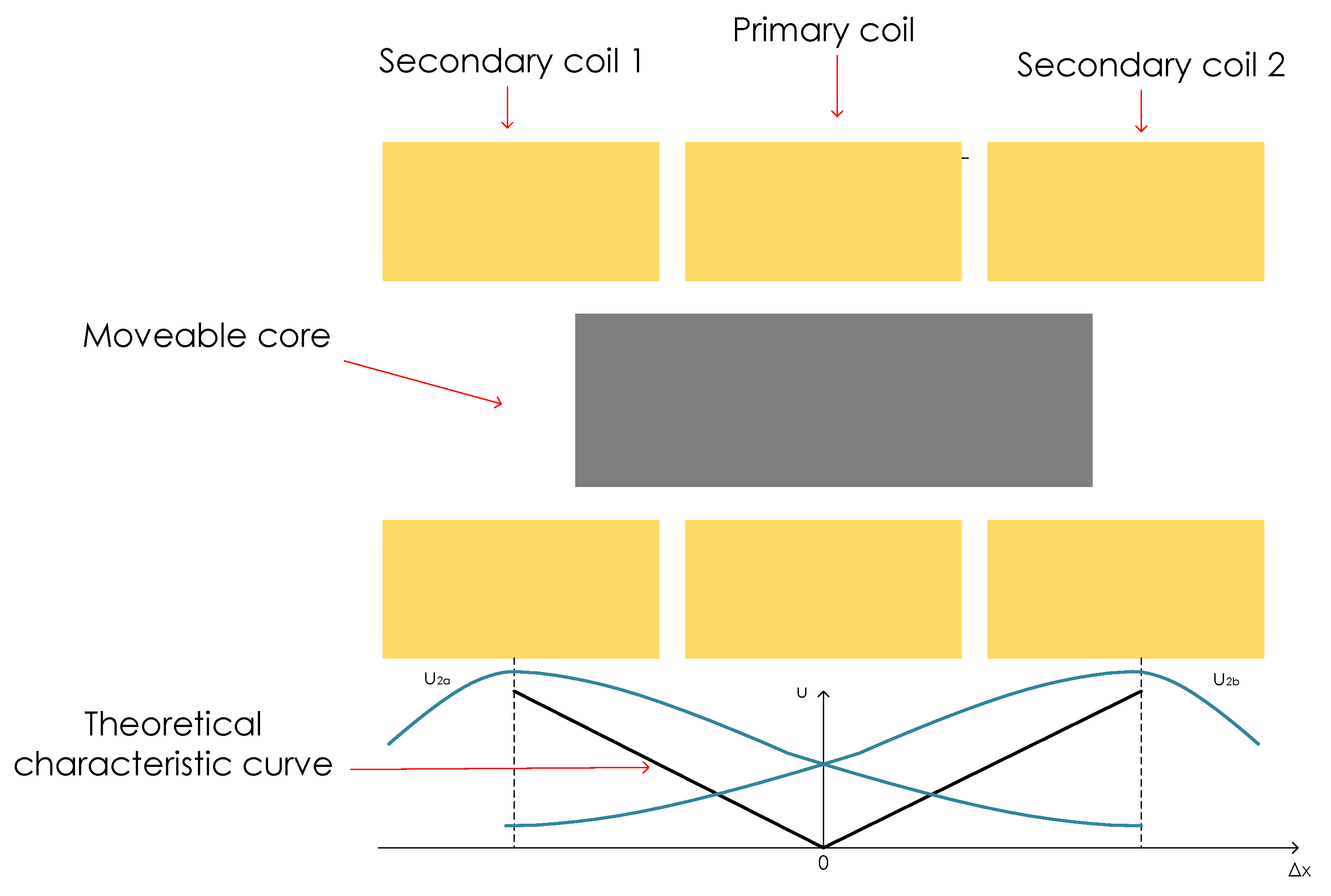
Linear variable differential transformer (LVDT) is a widely used linear displacement sensor. It is known for its robust structure, high linearity, high precision, and contactless nature [
2,
9]. LVTD is used for manufacturing, control, and scientific applications. The conventional LVDT design is of a cylindrical structure that includes a core, one primary, and two secondary windings [
2,
10,
11]. The core is usually made of a magnetic material, such as ferrites or soft magnetic materials.
LVDTs, like other inductive sensors, have some limitations. Limitations include limited linear range, stray capacitance effect, electromagnetic interference, and core loss. That is why various studies, techniques for improvement, as well as novel LVDT designs for specific, or broader, applications have been investigated [
10,
12,
13,
14,
15,
16]. In [
15], a compact LVDT for reactor experiment application was designed using analytical expressions, without the consideration of eddy current losses. In [
1], the study of effect of magnetic interference on the LVDT sensor was made. Modified design of LVDT is also proposed in [
10], with the study of the effect of the external magnetic field on the secondary using FEM-based software. Another modified design is presented in [
2], where a flat LVDT sensor is introduced with external armature made of solid iron and steel laminations. Minimization of the the error of the LVDT output signal due to the temperature effect is presented in [
17]. In [
2], effects of the induced eddy currents in the laminations are evident for frequency of 400 Hz. Inductive displacement sensors are analysed in [
5], where core loss influence on the quality factor is examined. A study of magnetic core materials used in LVDT is presented in [
18]. There, a correlation between eddy current effects and material sensitivity and linearity can be seen, emphasizing the need of eddy current analysis for LVDTs.
As previously mentioned, the cores of LVDTs can be made of different magnetic materials. In [
19,
20], the use of FE-rich amorphous wire and glass-covered amorphous wires as active core is presented. Additionally, ferrite is sometimes used to make the cores. However, ferrite has some drawbacks, such as high brittleness and low strength when geometric changes are needed. The analysis of core losses is necessary due to the use of various materials. Core losses can be categorized into hysteresis losses and eddy current losses. Hysteresis losses are proportional to the flux density and are represented by the area in the hysteresis loop. When ferromagnetic cores are used, eddy current losses can be an important consideration. Eddy currents are circulating currents that are induced in a conductor when it is subjected to a changing magnetic field. The flux moving through the core causes eddy currents to form, and losses resulting from those currents increase with frequency [
18]. In order to decrease the losses, laminated cores are used. In LVDT, the laminated core is typically made of a stack of thin sheets of a magnetic material. The thin laminations help to reduce eddy current losses by breaking up the continuity of the core and reducing the size of the circulating currents. The core material and the thickness of the laminations also play an important role in reducing eddy current losses. Investigation in [
5] has shown that eddy current losses are small enough that the core does not have to be laminated if the conductivity of the core is less than
S/m. For higher conductivities, laminations must be used in order to reduce the eddy current loss. Otherwise, the sensors quality factor and possible excitation frequency will be negatively affected due to eddy current losses. Therefore, due to their effects on the sensor accuracy, eddy current losses must, therefore, be considered when designing the sensor, as well. Additionally, it is important to take into account the frequency range in which the LVDT will be operated. The frequency response of an LVDT is determined by the design and construction of the transformer and the electronic signal conditioning circuit. It is important to note that LVDTs are sensitive to AC excitation frequency, the measurement frequency range will vary depending on the specific device and its design. In general, the eddy current losses are an important consideration in LVDT design but can be minimized through proper core design and materials selection.
Computational algorithms used for LVDTs mostly fail to take account of eddy-current effects [
21]. Despite the fact that numerous studies suggest that a comprehensive consideration of core losses, particularly eddy current losses, should be completed, the quantification of those losses is missing [
2,
5,
18,
21]. To the best of the authors’ knowledge, there are no scientific papers addressing specifically the eddy current losses in laminated cores of LVDTs. Therefore, it is the purpose of this paper to introduce the methodology for eddy current losses calculation of LVDTs that can be used during the design of LVDTs in order to optimize the dimensions of the LVDTs and help when selecting core materials, all for the goal of achieving the best measurement characteristics of LVDTs.
Analysis of eddy current problems in laminated cores is of great interest and it has been the topic of various papers [
22,
23,
24,
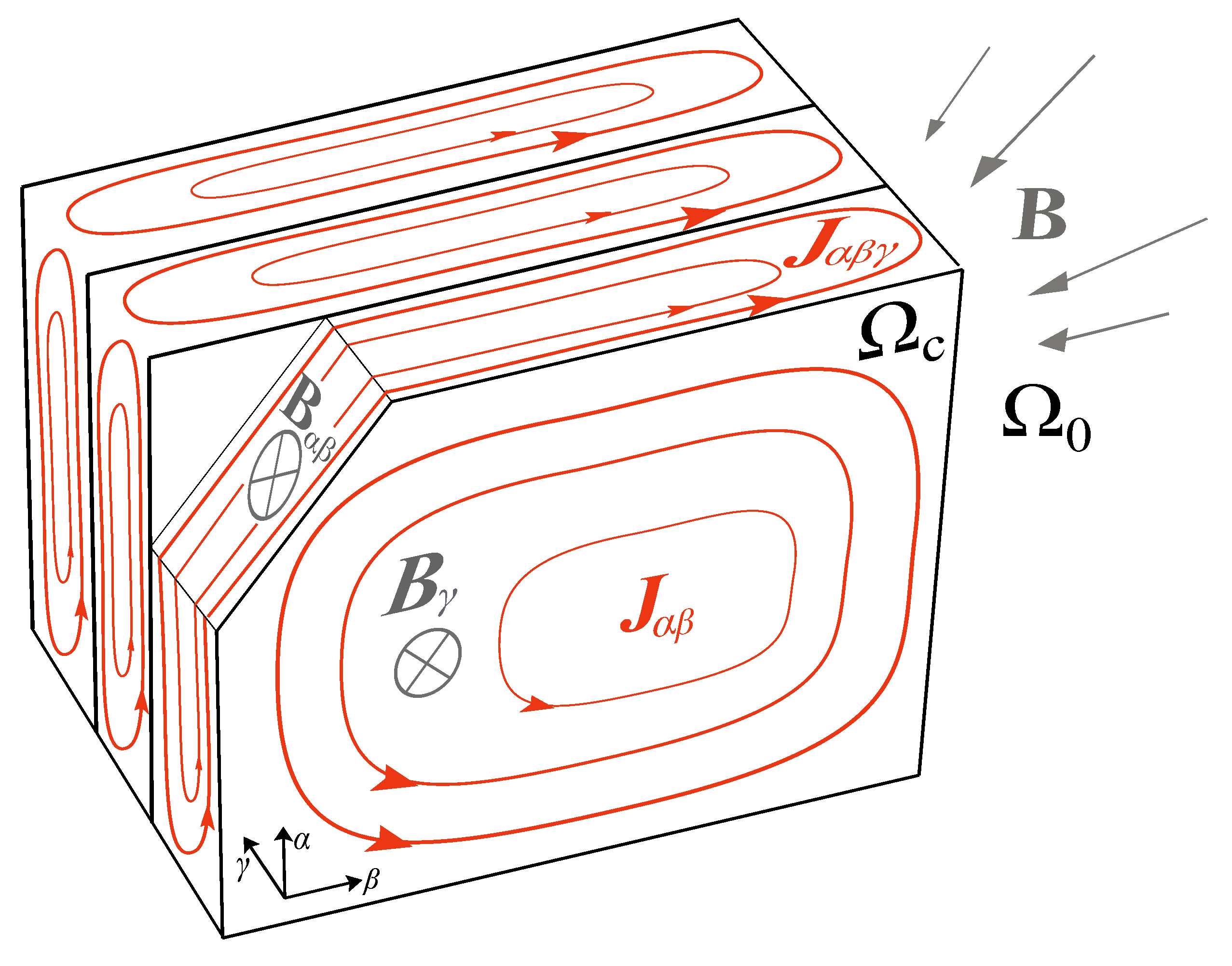
25]. However, calculation of eddy current losses requires taking into account differences between the open-type core and the closed-type core. Core of the conventionally designed LVDT is an open-core type [
26,
27]. Compared to a closed-type core, where the magnetic flux is closed mostly through the core, the of the magnetic flux of the open-type core passes through core/air interface and majority of the flux is dissipated perpendicularly to the lamination surfaces. As a result, the eddy currents generated by the stray magnetic flux that flow in wide loops tangential to the lamination surfaces can acquire considerable values. Moreover, since the problem domain of laminated medium of the represents a region of heterogeneous material, a very dense finite-element mesh is necessary inside the core region in order to account for eddy currents and material heterogeneity. Due to the lengthy simulation and the high demands on the computer’s working memory, such a problem is almost impossible to solve. Therefore, homogenization is frequently employed [
22,
23]. The particular geometry of open-type cores, along with the use of laminations, means that commercial software based on general techniques is usually not well adapted for analysis of eddy current losses. Overall, there is scarce research on the problem of eddy currents in open-type cores. A multi-scale approach that includes the modeling of eddy currents is presented in [
28], while a two-step method for total eddy currents calculation in an open-type laminated core is presented in [
26]. Research conducted in [
26] shows the advantages of the use of an
-formulation compared to
formulation when calculating eddy-current losses in open-type cores.
The methodology presented in this paper for the eddy current losses calculation in LVDT core is based on a 3D finite element method (FEM) approach based on a weak
-formulation. A similar approach was used in [
26], but in this paper a novel and improved approach for the elimination of redundant degrees of freedom which results in improved speed of convergence of the calculation. Results of the approach using a weak
-formulation with and without edge elements will be presented as validation of the acquired results and evidence of method advancement. The presented methodology is valid in linear cases, for LVDTs designed to work in the frequency range 50 Hz to 500 Hz, so the focus is on applications in the lower frequency range. The results obtained using the presented methodology are analysed using a LVDT model. The contribution of this paper is the demonstration of the correlation between eddy current losses and core displacement, frequency, and material properties by using a novel approach for the calculation of eddy current losses based on the weak
-formulation. Even through a conventional LVDT model was used for the analysis of eddy current losses, presented methodology can easily be used for calculation of losses in modified LVDT designs in which laminations in core or armature exist.
This paper is organized as follows:
Section 2 discusses LVDT design, gives an overview of eddy currents, and presents the robust method for fast calculation of eddy current losses. Analysis of the results achieved by using said method and validation, along with discussion are presented in
Section 2. In
Section 4, the conclusion is made.
3. Results and Discussion
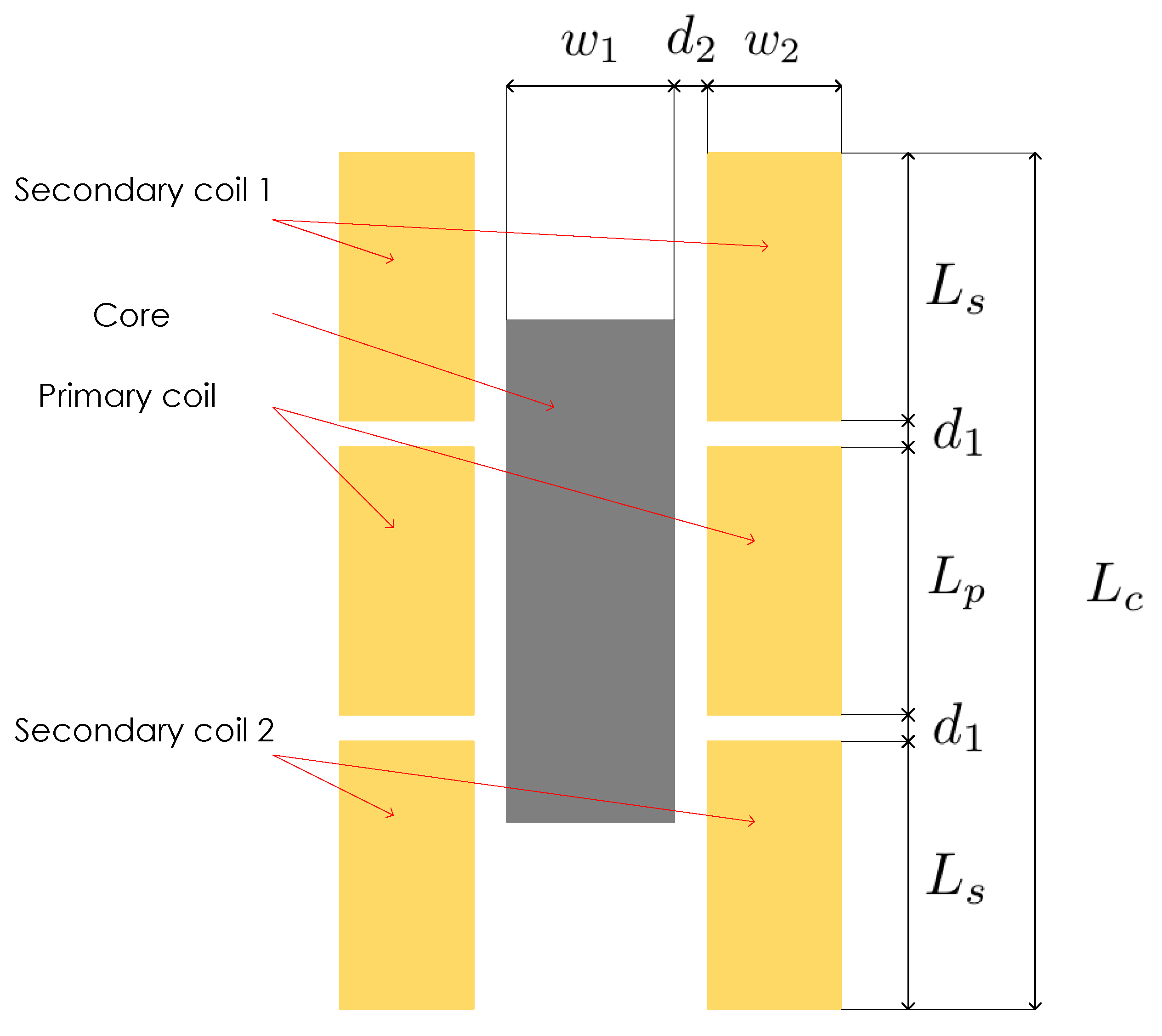
A 3D model of a LVDT is used for the analysis of the proposed methodology for calculation of eddy current losses. A weak
-formulation, described in
Section 2.2 of
Section 2, is used to calculate the eddy current losses in LVDT model. The LVDT model corresponds to the one shown in
Figure 5, with the parameters and their physical values listed in
Table 1. The geometrical dimensions are merely indicative. Since the analysis was performed for different frequencies and materials, those parameters are listed in
Table 2.
Firstly, in order to validate the proposed methodology that uses a weak
-formulation with proposed improved elimination of redundant degrees of freedom, a comparison of two types of FEM simulations was performed. One simulation was completed with a novel approach, and the other was completed by using the typical weak
-formulation. The second approach was already validated in [
26]. An iterative technique based on the CG algorithm is used to solve the linear system arising from the formulation in the simulations. Both simulations were run on the same mesh. The simulations were run on the LVDT model with core centred at 0 mm (without displacement), for the core material of relative permeability 10,000 and conductivity of core
S/m, at frequency of 50 Hz. The amount of total eddy current losses is equal in both cases and amounts to 5.2 mW. However, due to the elimination of redundant edge elements, there was a major difference in calculation time. Since the current vector potential is used as the excitation, no direct modelling of the coil is required. This is why it is possible to use the same mesh for all positions and the core position for the same number of mesh elements does not significantly affect the duration of the simulation for different core positions. The number of elements of the core mesh is 46,800, while the number of elements in the air is 401,573. For comparison purposes, the same mesh was used for both formulations. While the simulation for a single position that used the typical
-formulation ran for 6400 s, the simulation using the proposed approach ran for 2586 s, thus improving the time 2.47 times which is a significant improvement.
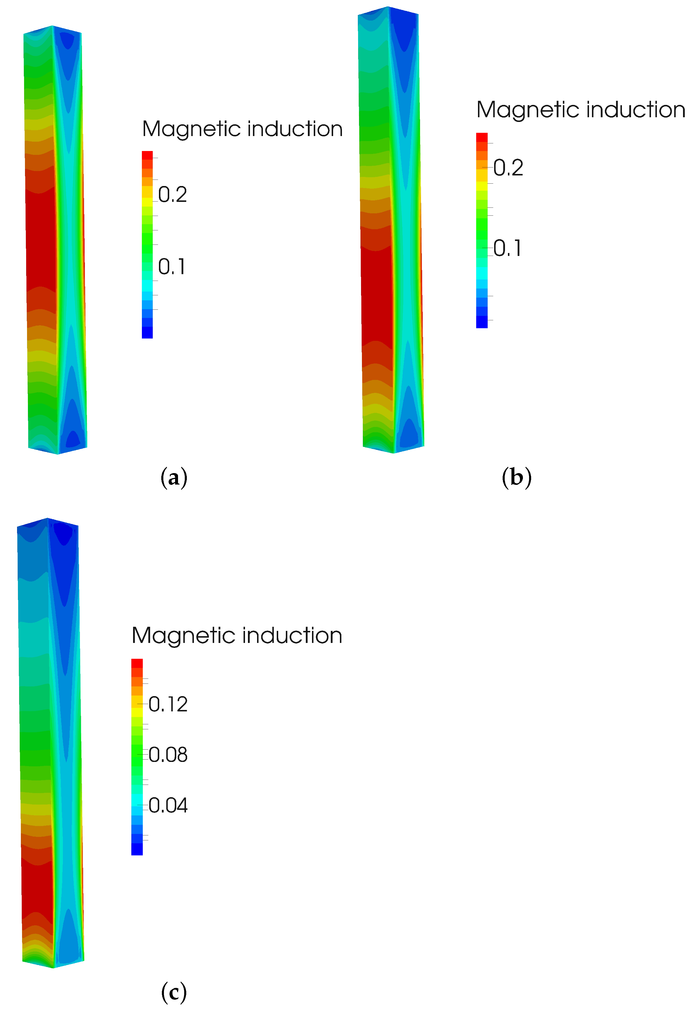
After that, multiple simulations of eddy current losses based on the core displacement were made.
Figure 6 presents magnetic induction at frequency of 50 Hz, for the core material of relative permeability 10,000 and conductivity of core
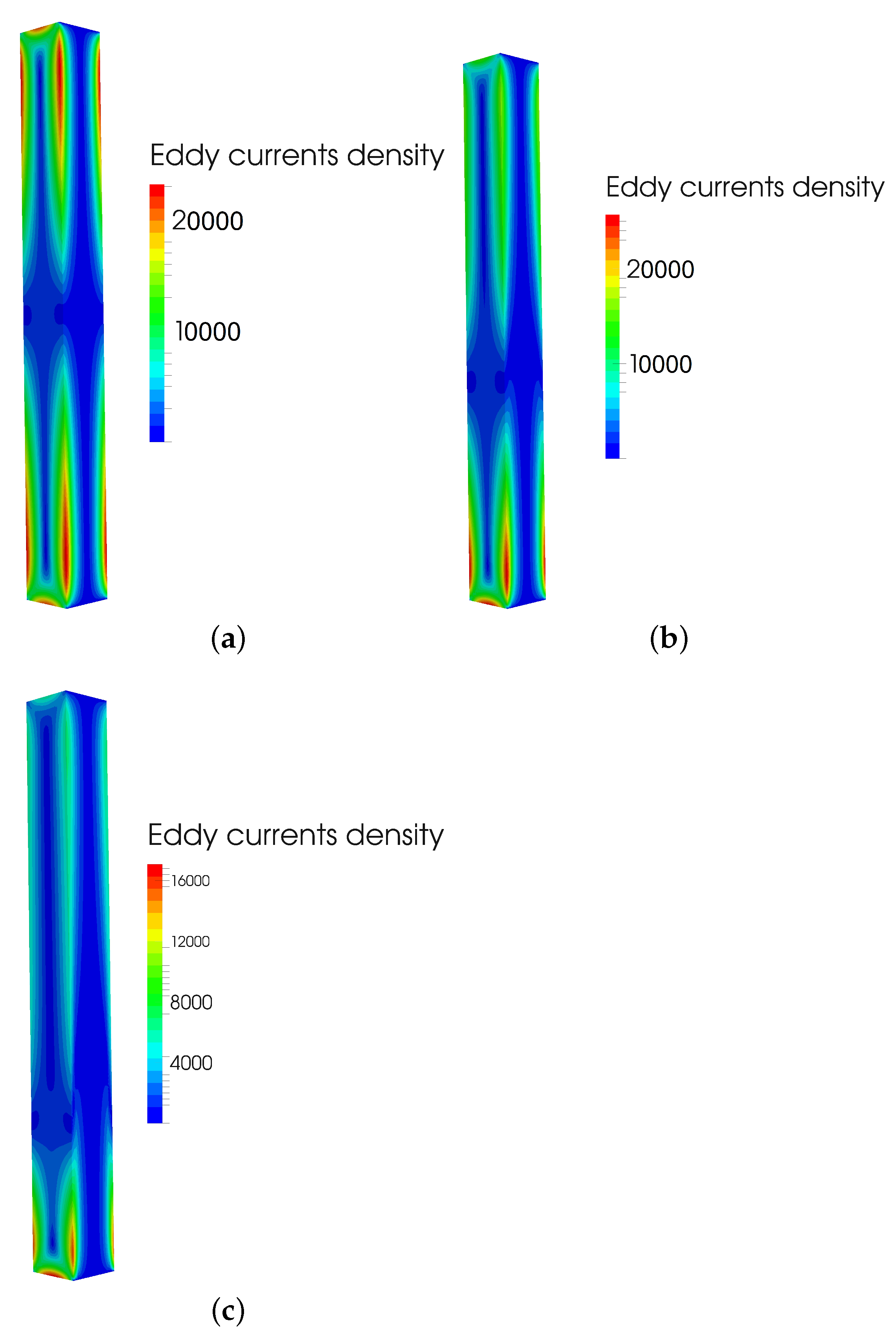
S/m at three positions, position 1 of core at 0 mm without displacement, position 2 in which core is displaced by 20 mm, and position 3 with the displacement of 50 mm. Similarly, for the same positions, material, and frequency,
Figure 7 presents eddy current density. Eddy currents are, therefore, most influential at position without core displacement, as the magnetic induction is then at its highest.
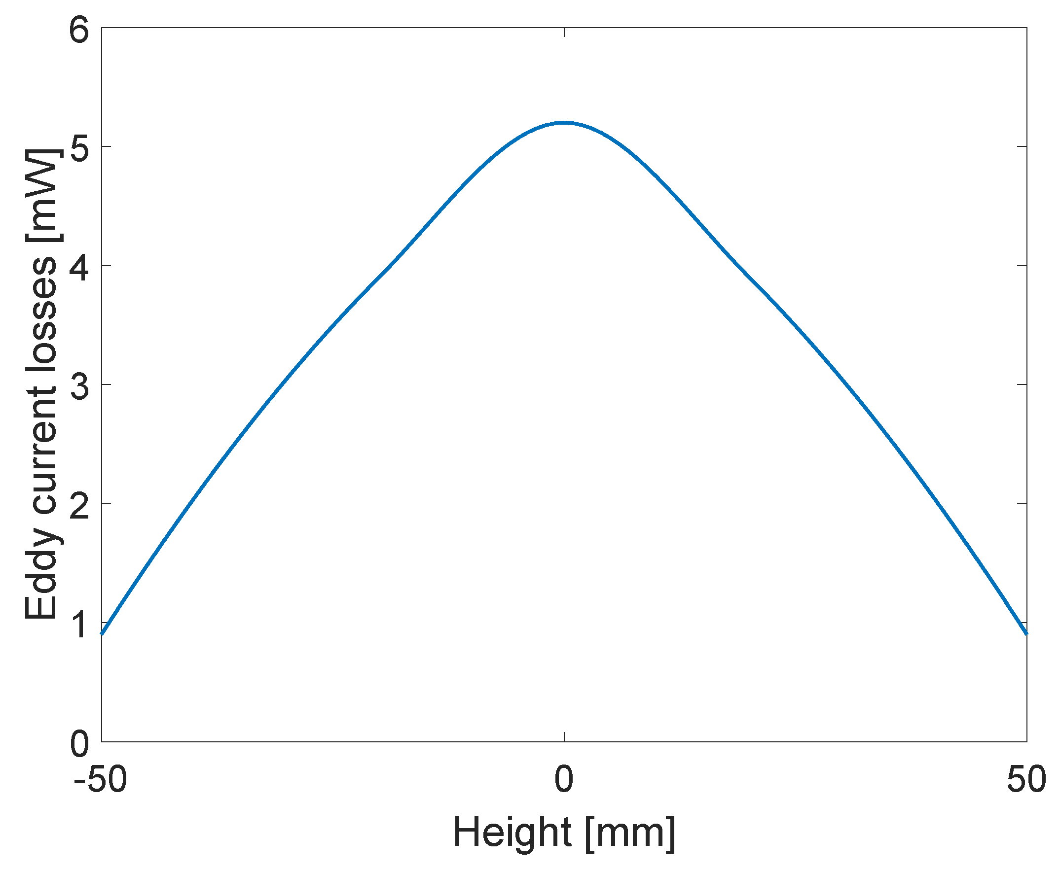
Then, the core was moved from position −50 mm to 50 mm, at 10 mm intervals, with the position of centre where there is no displacement at 0 mm. For those positions, eddy current losses were calculated for material properties of relative permeability 10,000 and conductivity of core
S/m, at frequency of 50 Hz. The results are presented in
Figure 8, with interpolation performed for other positions. Not only can the influence of eddy currents be seen from
Figure 6, like in previous research, but the presented methodology has enabled the quantification of those losses, as seen in
Figure 8.
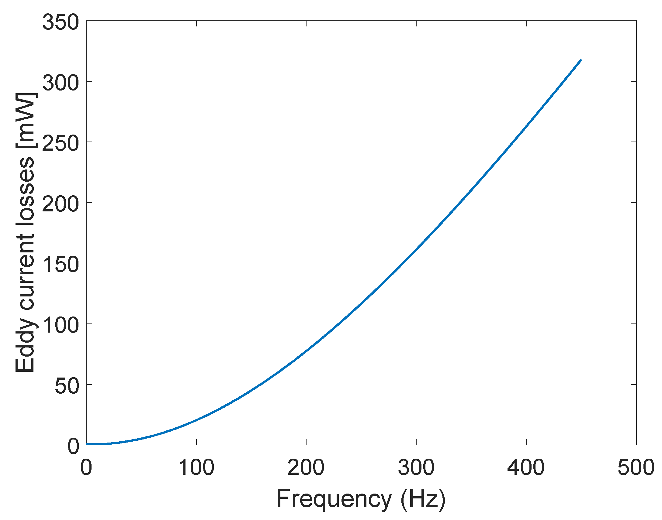
Eddy current losses were also calculated at position of the laminated core at 0 mm without displacement, for the core material of relative permeability 10,000 and conductivity of core
S/m, at frequencies ranging from 50 Hz to 450 Hz with the step of 100 Hz. Interpolated results are shown in
Figure 9. As expected, eddy current losses rise with frequency. Presented methodology enables the designer of LVDT to calculate the losses at wanted working frequency and then determine whether to modify the LVDT core properties, i.e., change the core material or increase the number of laminations in order to lower the losses and thus increase reliability.
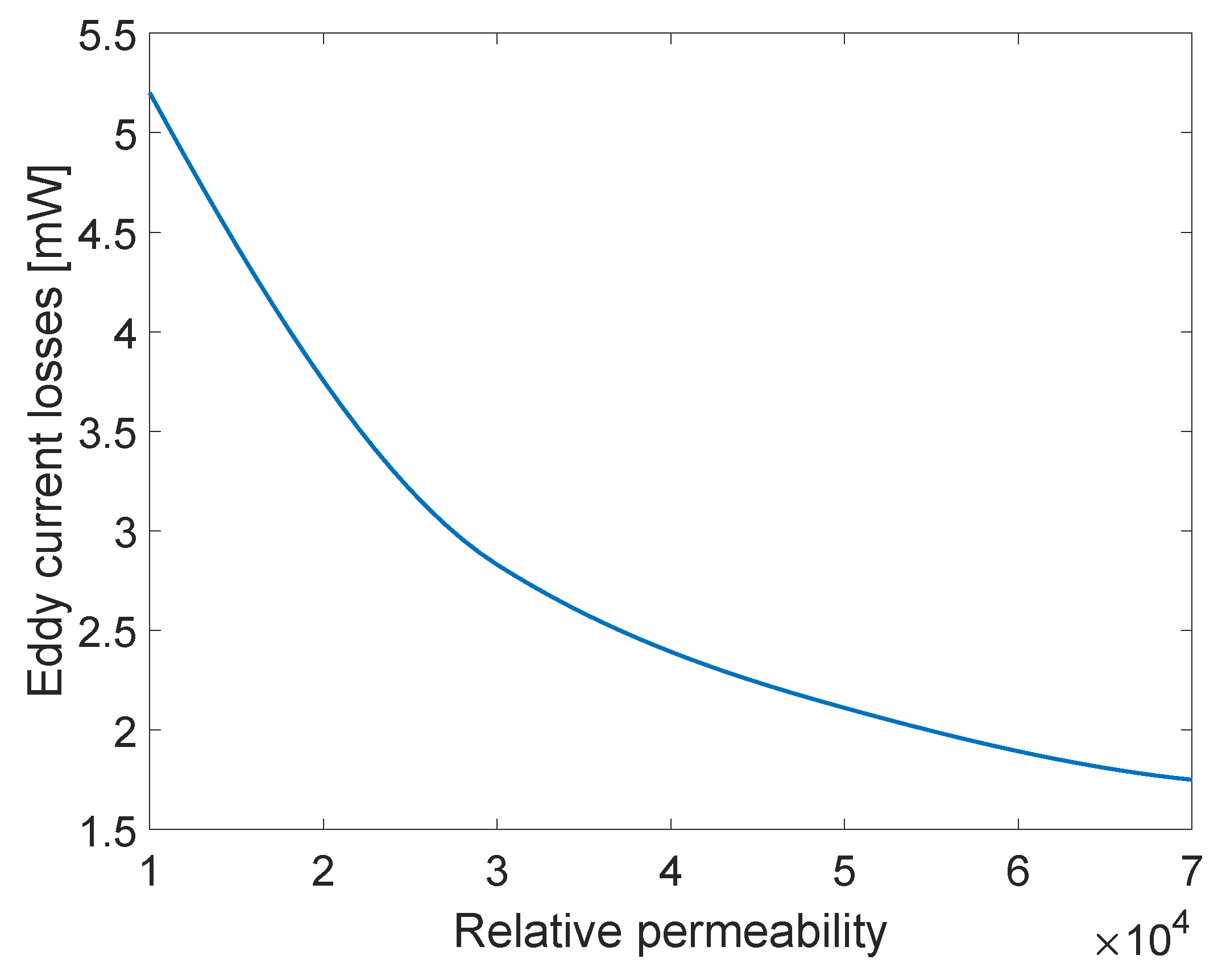
An analysis of eddy current losses for different core materials of a laminated core was also made. Materials of relative permeability of 10,000, 30,000, 50,000, and 70,000 were used. Corresponding core conductivity was always set to
S/m. The results are presented in
Figure 10. The losses decrease with the increase in relative permeability, as is expected. Since permeability is directly linked to the performance and reliability of the device [
18], and some materials are in certain periods not available, it is important to be able to obtain knowledge of eddy current losses for a range different materials.
Results presented in this paper, along with the conclusions established in [
5,
18] about the influence of eddy currents on the sensor performance, can be used to develop a set of limitations and standards in LVDT design dependent on eddy current losses with the goal of sensor optimization. Methodology for the calculation of eddy current losses in LVDTs presented in this paper can also be used for modified designs of LVDTs, different materials and different frequencies, depending on the final product requirements.
4. Conclusions
LVDTs are regularly used magnetic displacement sensors due to their high precision and robust design. Due to the open-type core a typical LVDT has, depending on the core material, it is very important to take eddy currents into the account. This is especially important if steel materials are used. It is important to take into consideration the magnetic permeabilities and electrical conductivities of magnetic materials in the design of magnetic displacement sensors. The frequency at which the sensor operates should also be considered when choosing the core materials due to the increase in eddy current losses with frequency.
In this paper, the presented approach for eddy current losses calculation using a weak -formulation has taken into the account the particularity of the geometry of the LVDT core. Numerical homogenization offers a simple way of taking into account edge effects for eddy currents induced by the magnetic flux tangential to the lamination surfaces. The results are in good accord with other potential approaches. The suggested method, which produces precise results, is simple to utilize for LVDT design optimization. Analysis of the results obtained using presented methodology for eddy current losses calculation in LVDTs enables the designer of those devices to know the losses depending on frequency, material, and number of laminations and, thus, optimize the design of the LVDT. That means that the presented methodology could influence the improvement of design standards for LVDTs, as well as other electromagnetic devices. The simulation results take into account the standard LVDT design, but the methodology can also be implemented for the analysis of modified LVDT designs.
The proposed eddy current losses methodology’s scientific goal is to provide a tool that can be used to study the eddy current phenomenon that occurs in LVDTs. Further work could be based on the development of improved standardized design instructions dependant on the core loss ratio of LVDTs dependent on frequency, material characteristic, material availability, and necessary dimensions of the designed sensor.


