
An Indoor Location-Based Augmented Reality Framework


Abstract
1. Introduction
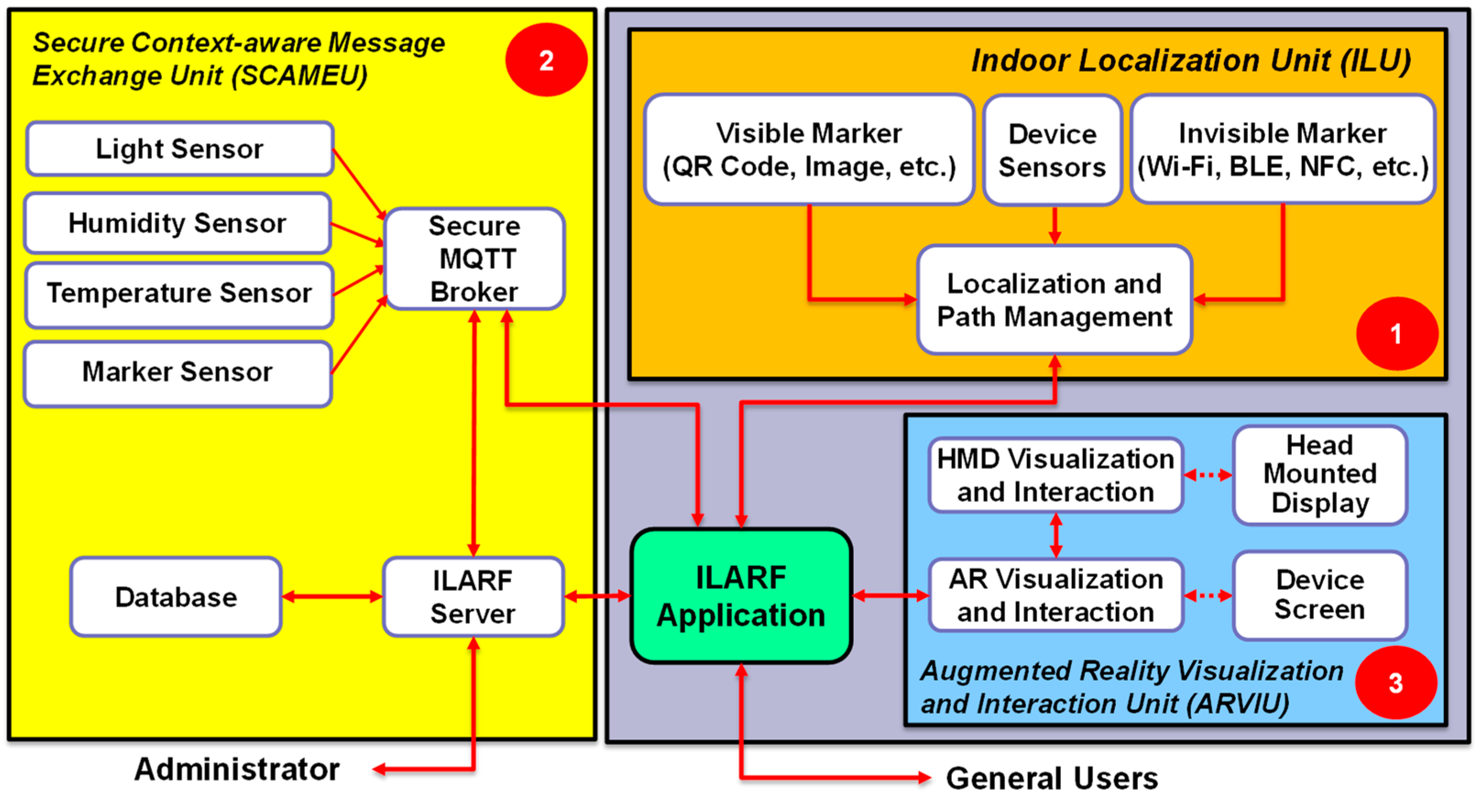
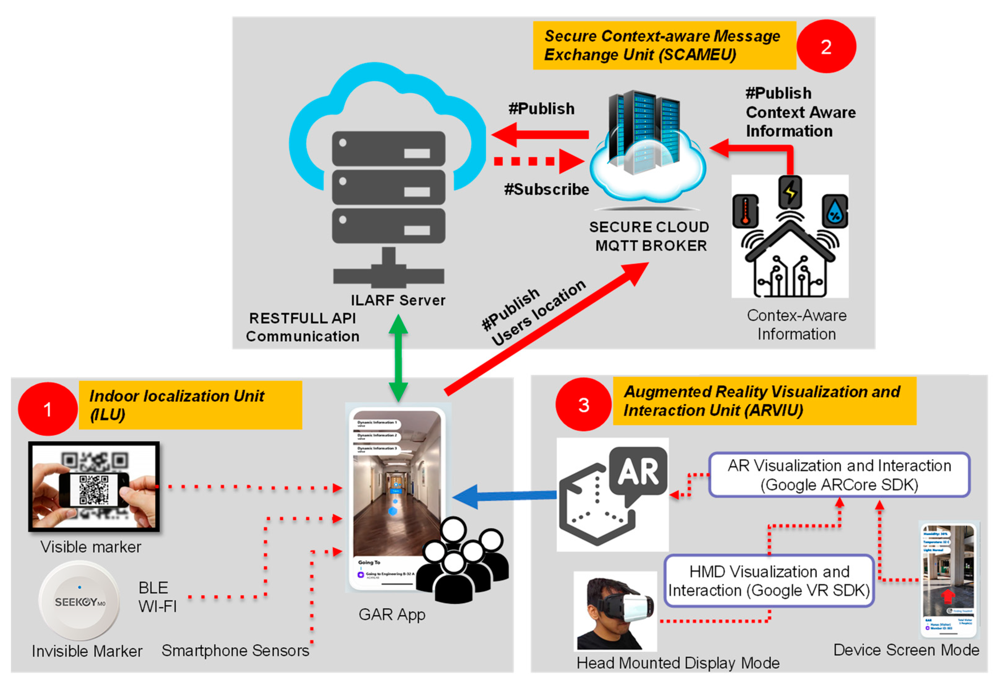
2. ILARF
2.1. Indoor Localization Unit (ILU)
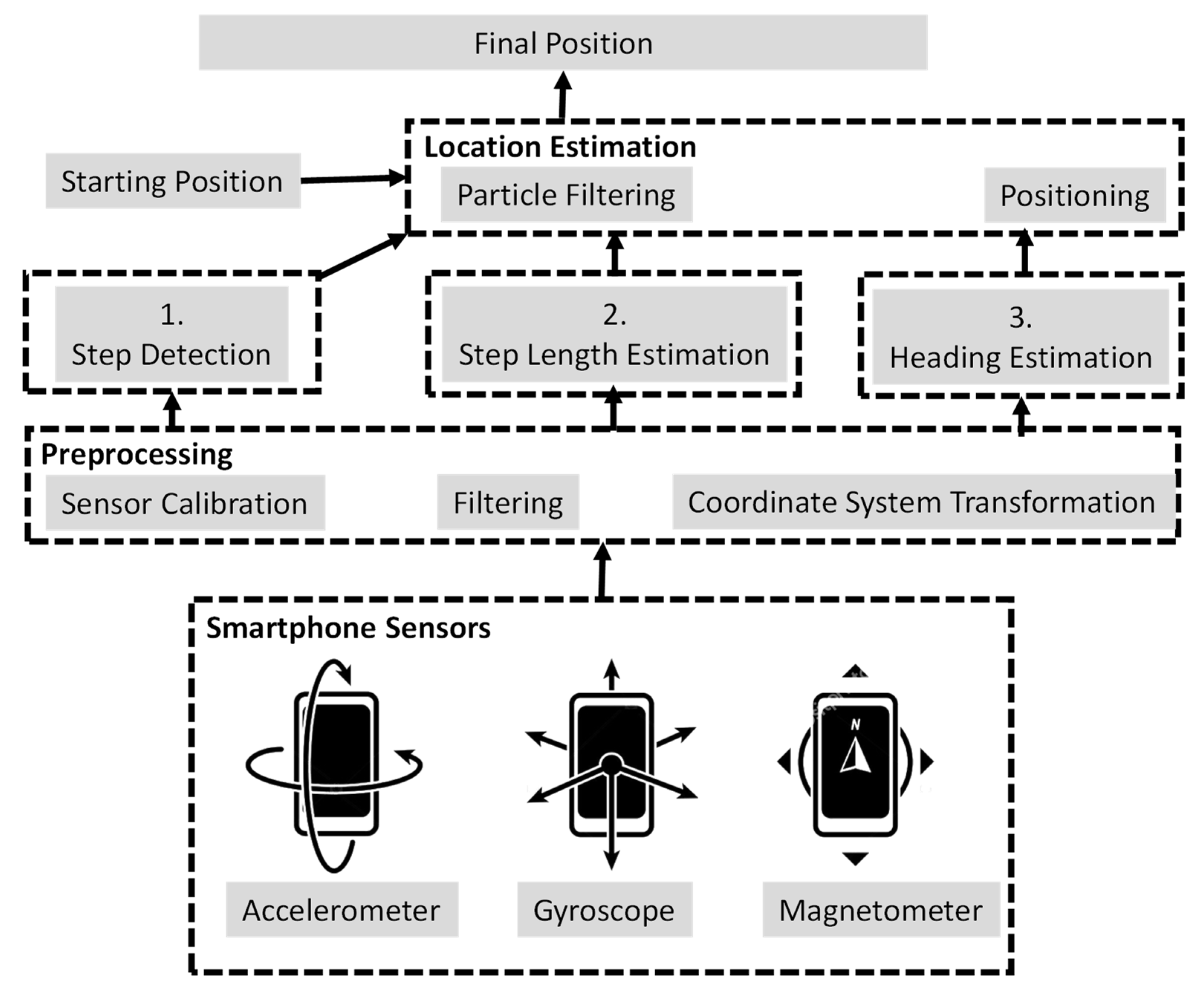
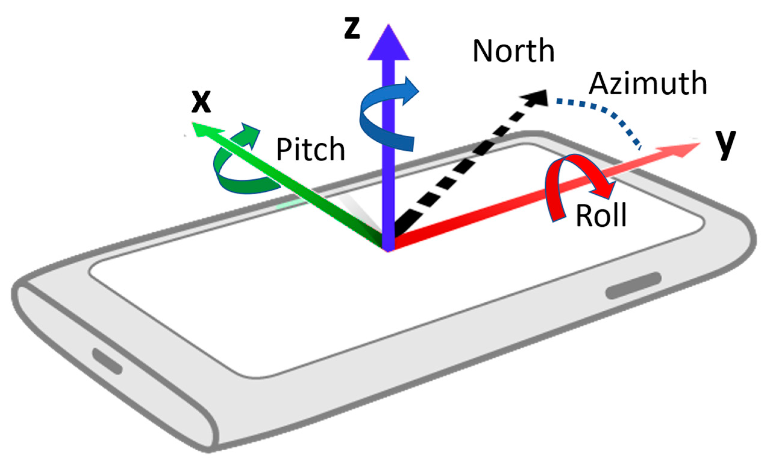
2.1.1. Inertia-Based IL Methods
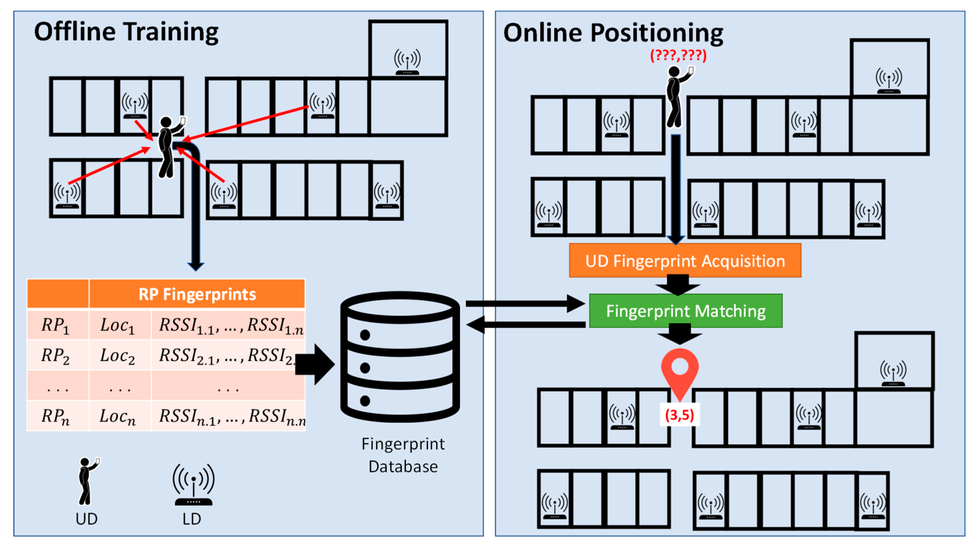
2.1.2. Fingerprint-Based IL Methods
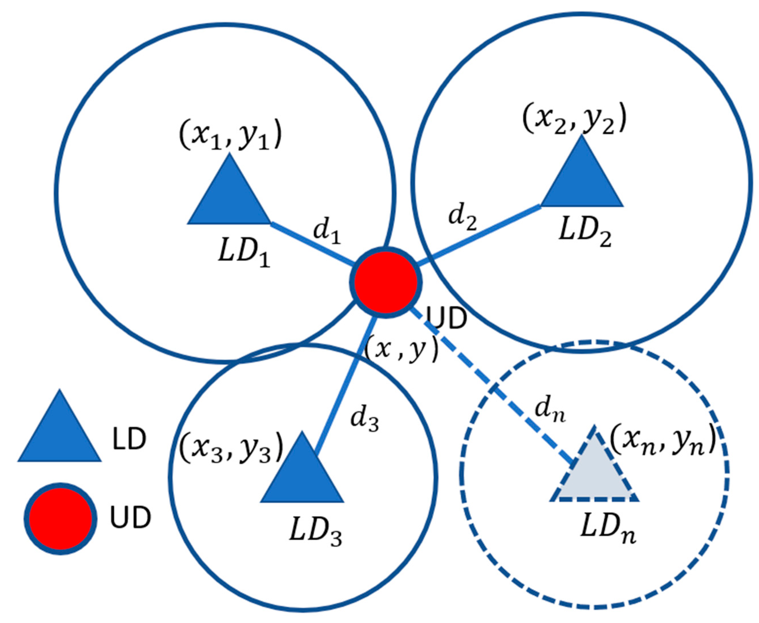
2.1.3. Multilateration-Based IL Methods
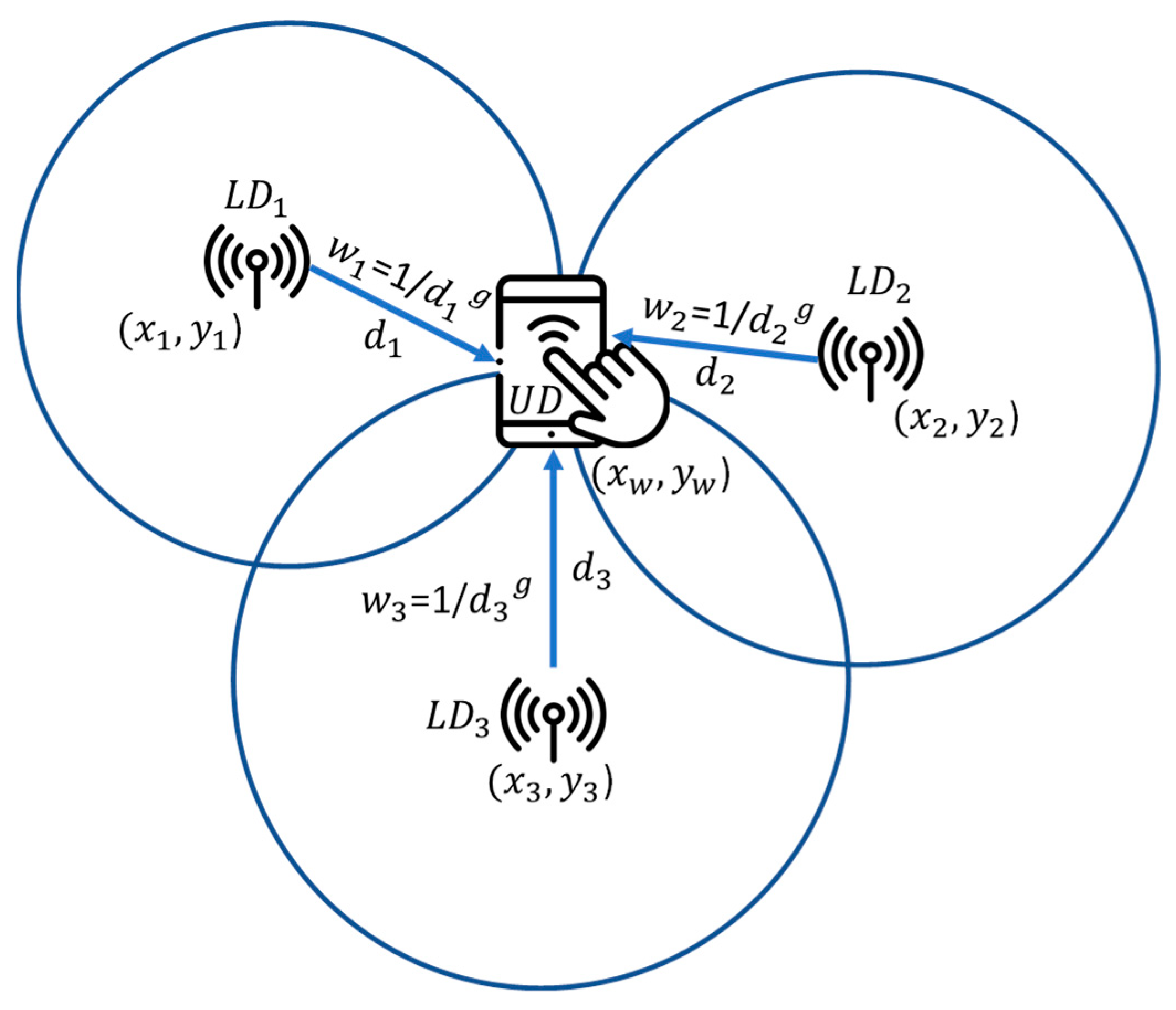
2.1.4. Centroid-Based IL Methods
2.1.5. Marker-Based IL Methods
2.2. Secure Context-Aware Message Exchange Unit
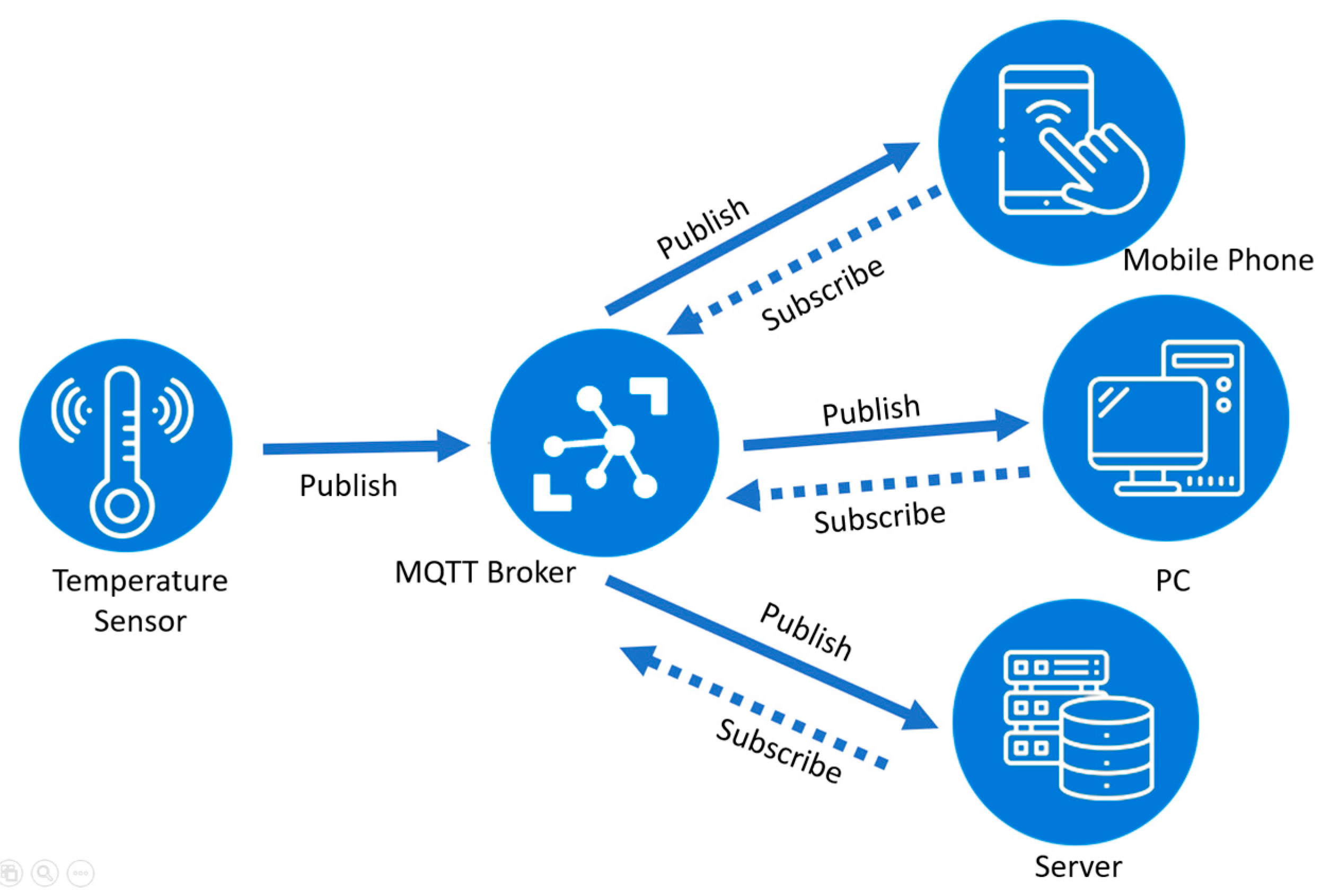
2.2.1. MQTT
2.2.2. HTTP
2.2.3. CoAP
2.2.4. AMQP
2.2.5. TLS/SSL
2.3. AR Visualization and Interaction Unit
2.3.1. ARVIU Device Screen Mode
2.3.2. ARVIU HMD Mode
3. Gym Augmented Reality
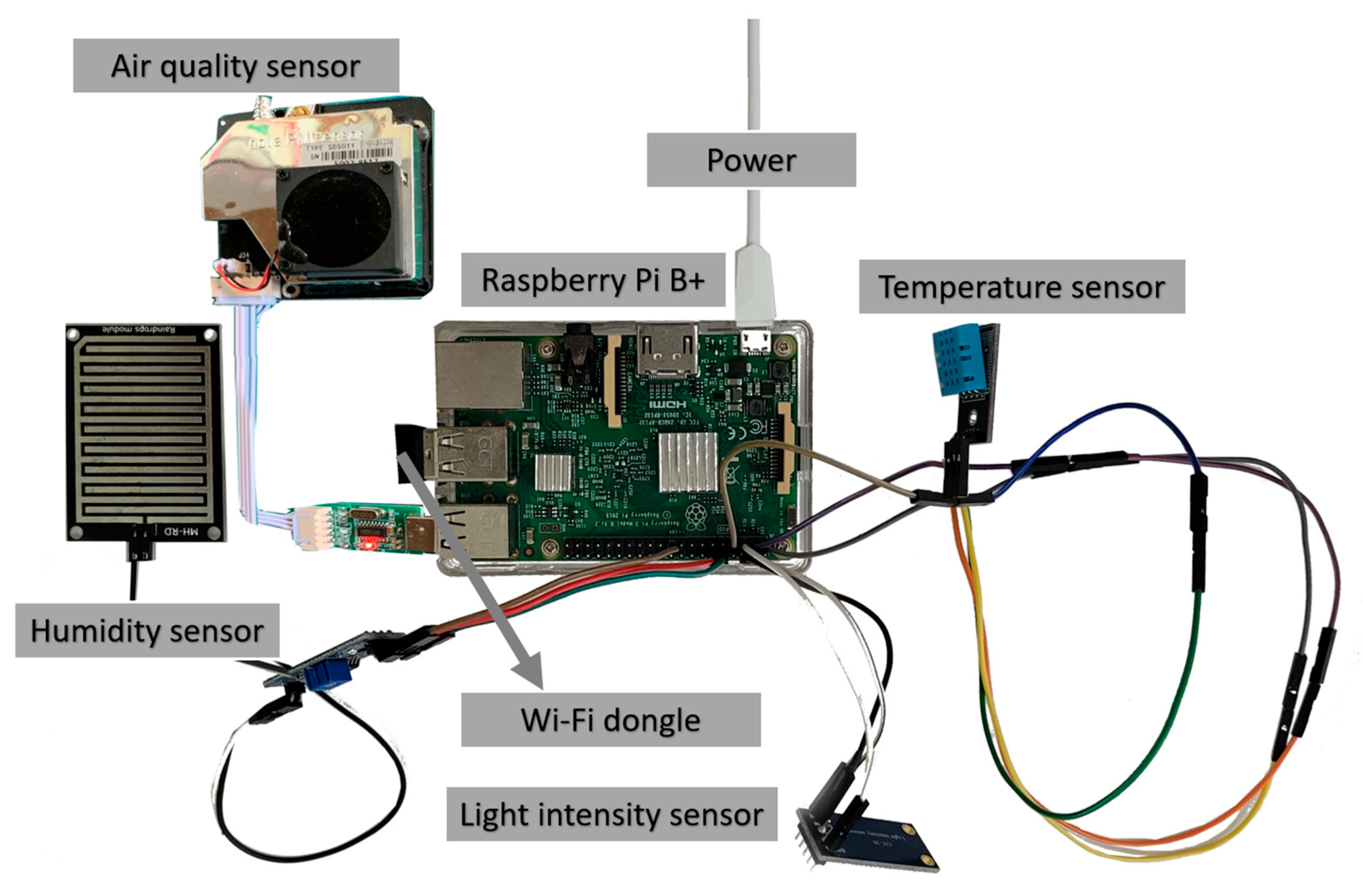
3.1. Hardware and Software Specifications
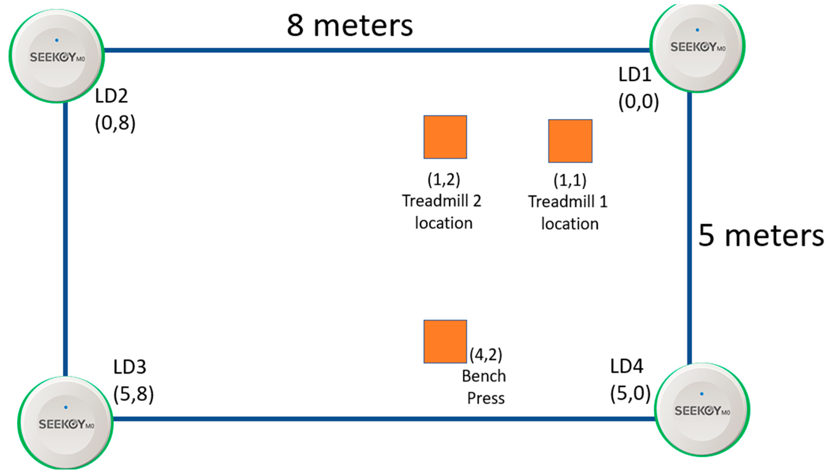
3.2. ILU Implementation
3.2.1. ILU Using Visible Markers
3.2.2. ILU Using Invisible Markers
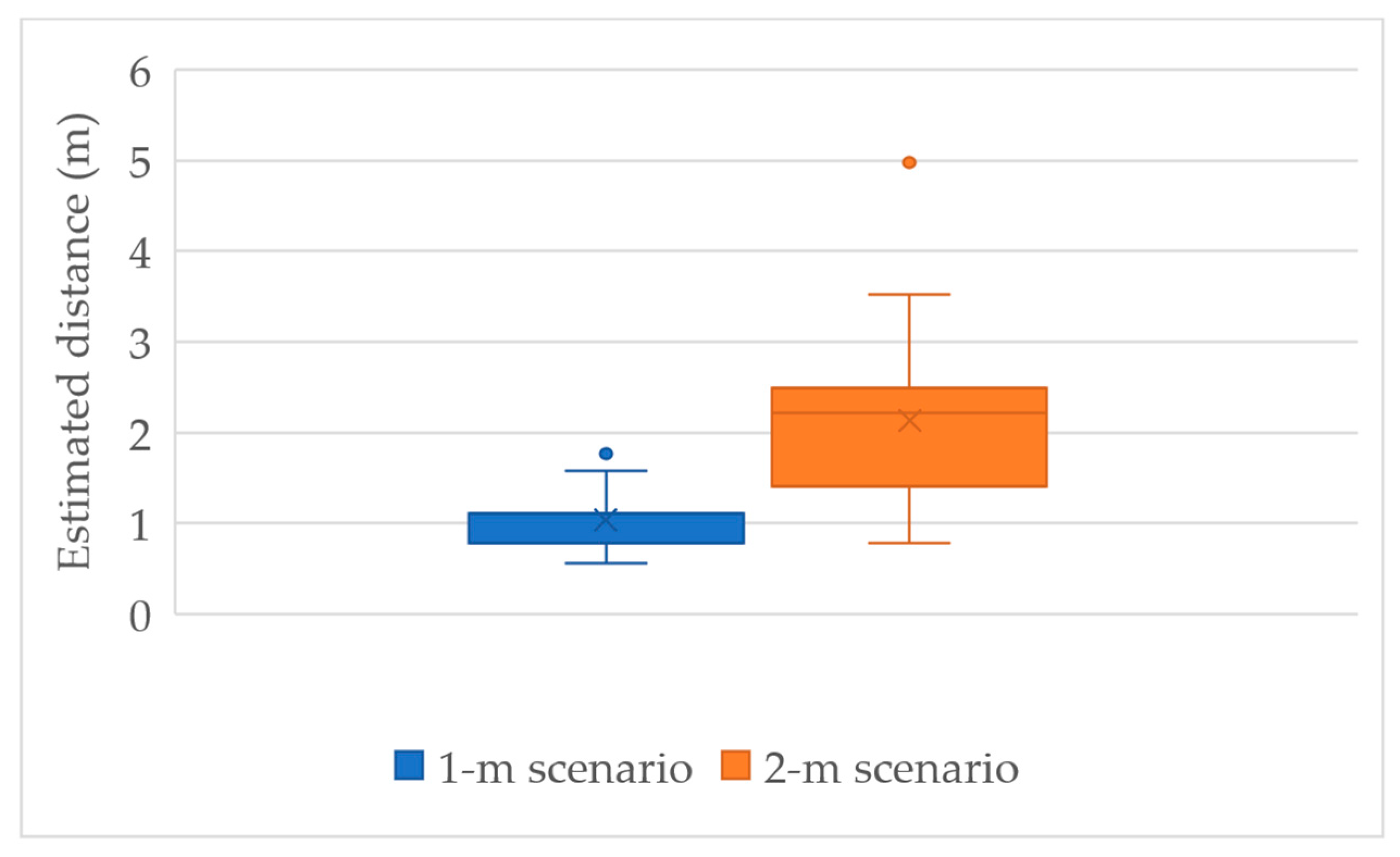
3.2.3. ILU Using UD Sensors
3.2.4. ILU Using Both QR Codes and Invisible Markers
3.3. SCAMEU Implementation
3.3.1. Secure Cloud MQTT Broker
3.3.2. ILARF Server
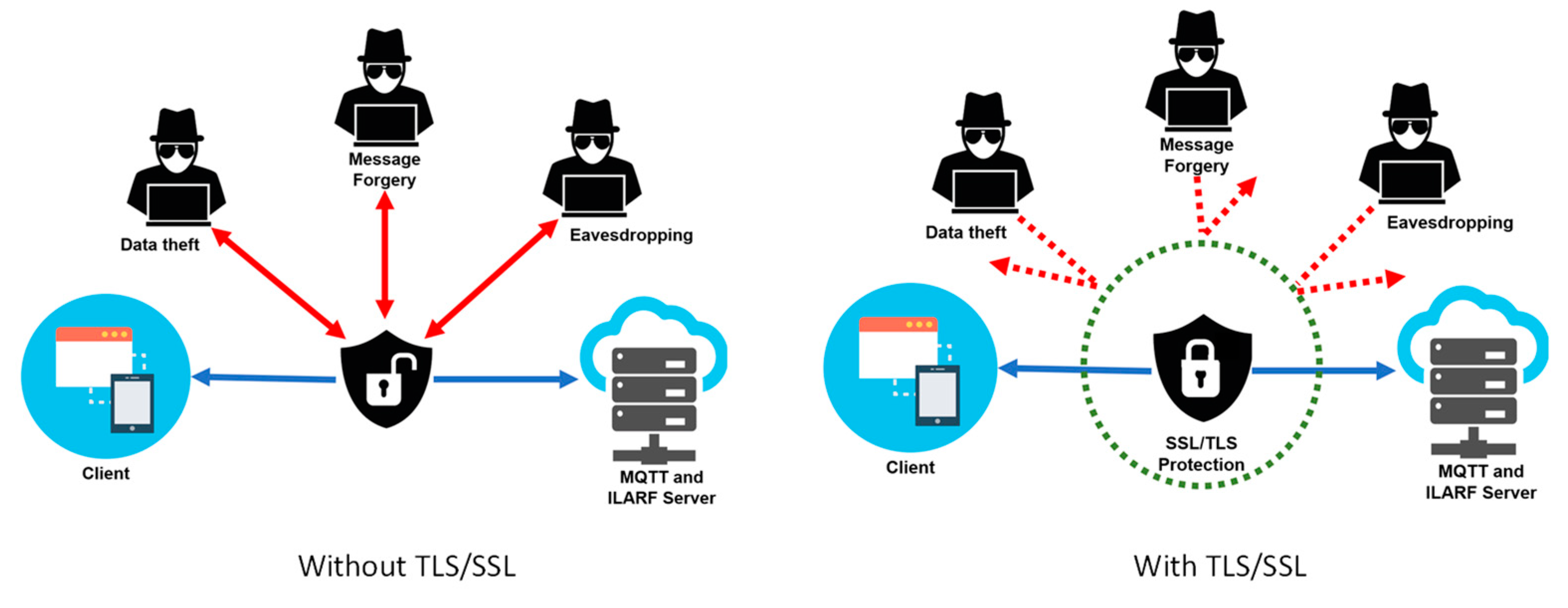
3.3.3. TLS/SSL Implementation
3.4. ARVIU Implementation
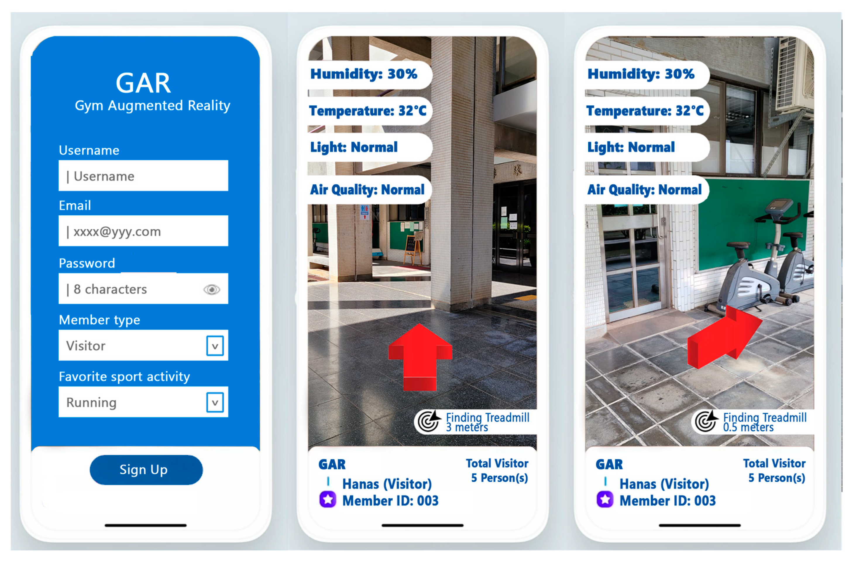
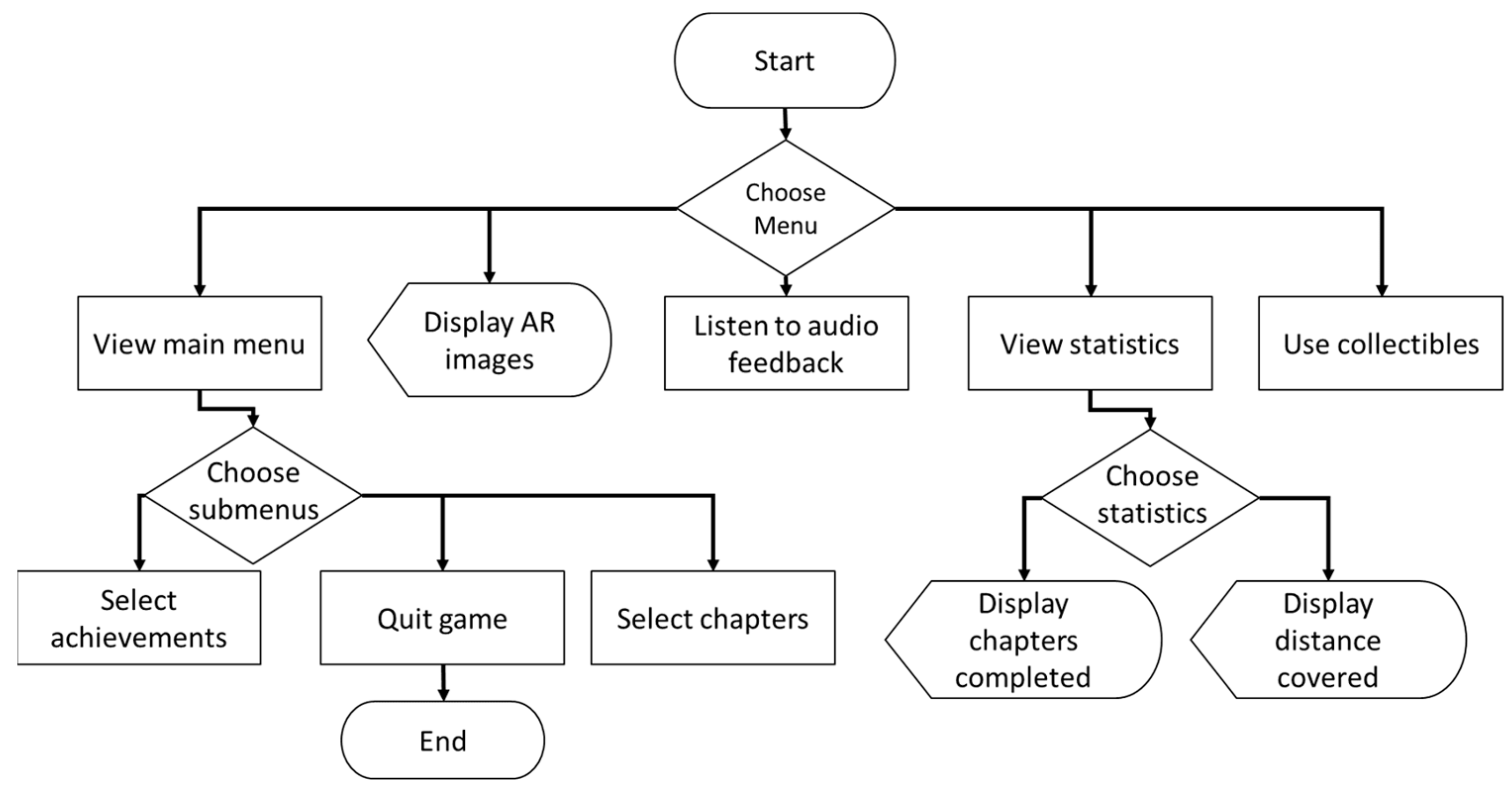
3.4.1. GAR Device Screen Mode
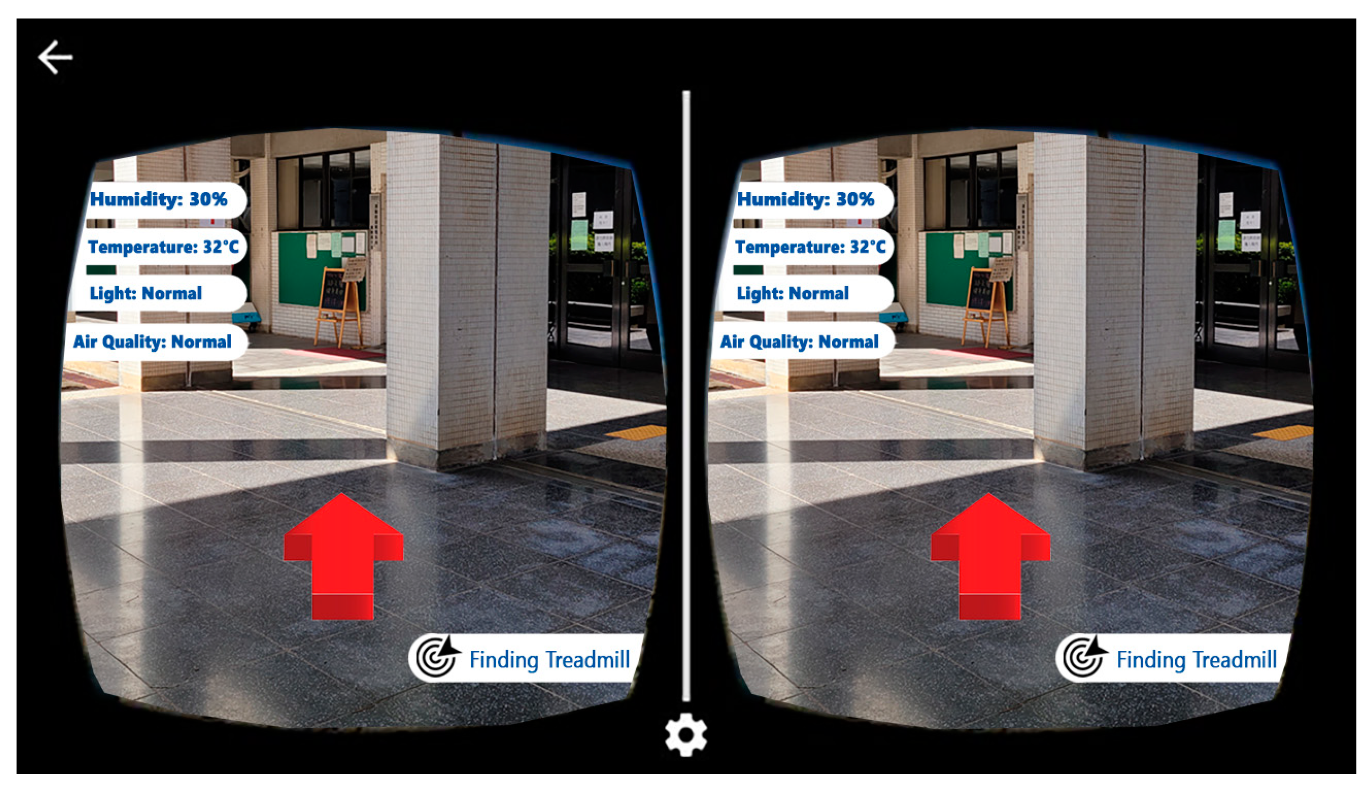
3.4.2. GAR HMD Mode
4. Comparison of GAR and Related Systems
4.1. Overview of Related Systems
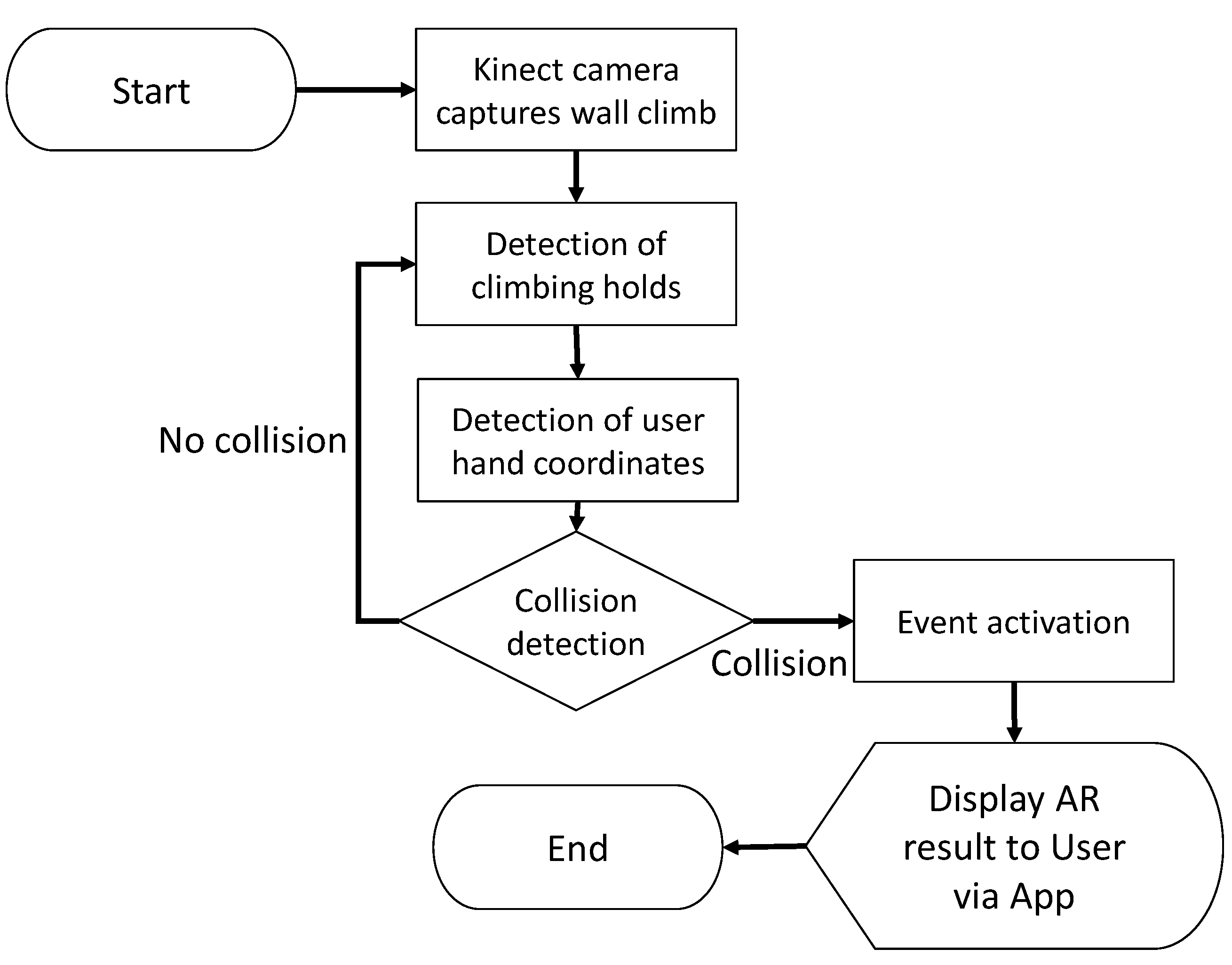
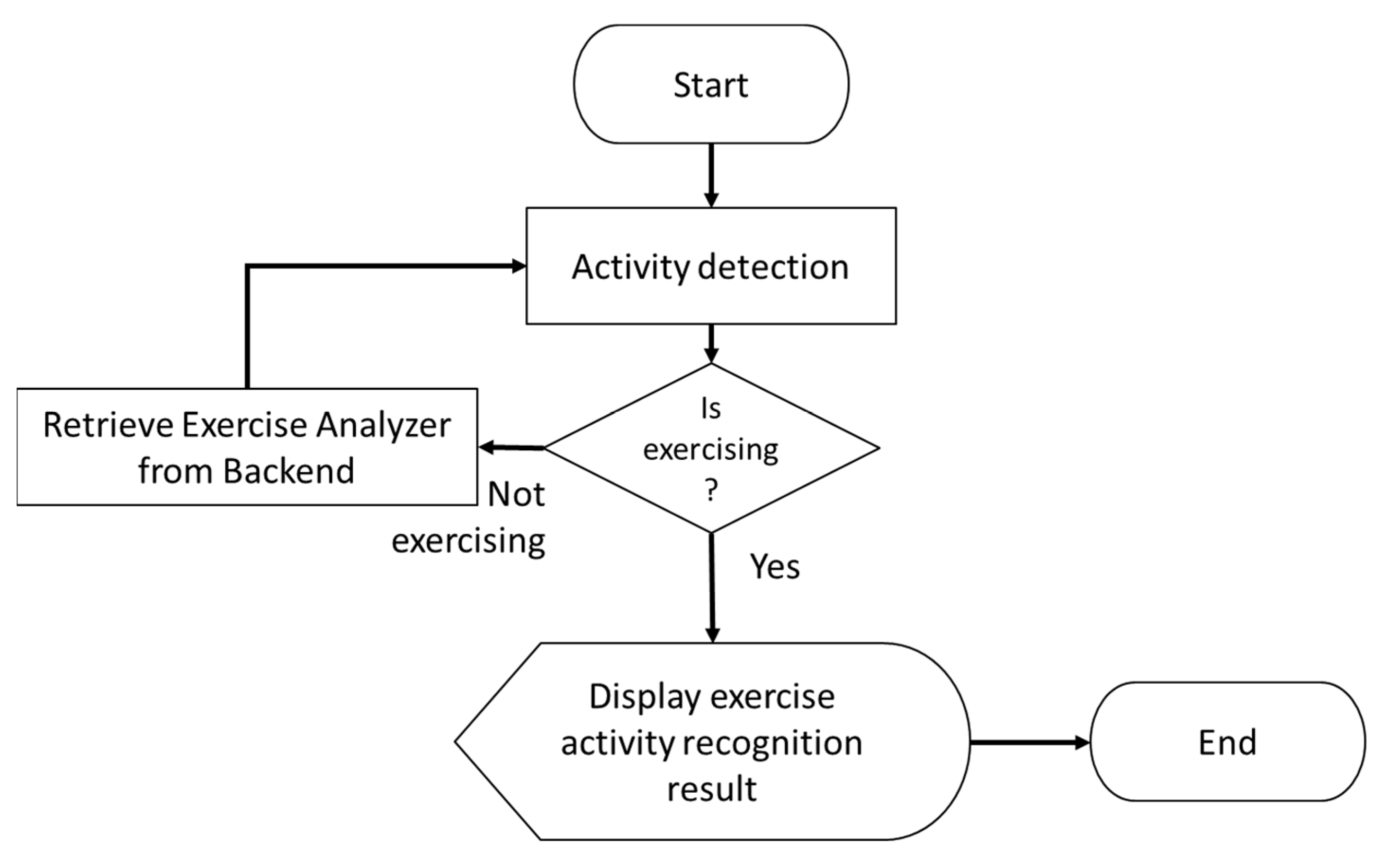
4.2. Comparison of GAR and Related Systems
5. Conclusions
Author Contributions
Funding
Institutional Review Board Statement
Informed Consent Statement
Data Availability Statement
Conflicts of Interest
References
- Zafari, F.; Gkelias, A.; Leung, K.K. A survey of indoor localization systems and technologies. IEEE Commun. Surv. Tutor. 2019, 21, 2568–2599. [Google Scholar] [CrossRef]
- Sirohi, P.; Agarwal, A.; Maheshwari, P. A survey on augmented virtual reality: Applications and future directions. In Proceedings of the 2020 Seventh International Conference on Information Technology Trends (ITT), Abu Dhabi, United Arab Emirates, 25–26 November 2020; pp. 99–106. [Google Scholar]
- El-Sheimy, N.; Li, Y. Indoor navigation: State of the art and future trends. Satell. Navig. 2021, 2, 1–23. [Google Scholar] [CrossRef]
- Vy, T.; Nguyen, T.; Shin, Y. Pedestrian indoor localization and tracking using hybrid Wi-Fi/PDR for iPhones. In Proceedings of the 2021 IEEE 93rd Vehicular Technology Conference (VTC2021-Spring), Helsinki, Finland, 25–28 April 2021; pp. 1–7. [Google Scholar]
- Shamsfakhr, F.; Antonucci, A.; Palopoli, L.; Macii, D.; Fontanelli, D. Indoor localization uncertainty control based on wireless ranging for Robots Path Planning. IEEE Trans. Instrum. Meas. 2022, 71, 1–11. [Google Scholar] [CrossRef]
- Ma, W.; Zhang, S.; Huang, J. Mobile augmented reality based indoor map for improving geo-visualization. PeerJ Comput. Sci. 2021, 7, e704. [Google Scholar] [CrossRef] [PubMed]
- de Souza Cardoso, L.F.; Mariano FC, M.Q.; Zorzal, E.R. A survey of industrial augmented reality. Comput. Ind. Eng. 2020, 139, 106159. [Google Scholar] [CrossRef]
- Siriwardhana, Y.; Porambage, P.; Liyanage, M.; Ylianttila, M. A survey on mobile augmented reality with 5G mobile edge computing: Architectures, applications, and technical aspects. IEEE Commun. Surv. Tutor. 2021, 23, 1160–1192. [Google Scholar] [CrossRef]
- Baek, F.; Ha, I.; Kim, H. Augmented reality system for facility management using image-based indoor localization. Autom. Constr. 2019, 99, 18–26. [Google Scholar] [CrossRef]
- An, H.W.; Moon, N. Indoor positioning system using pyramidal beacon in mobile augmented reality. In Advances in Computer Science and Ubiquitous Computing; Springer: Singapore, 2021; pp. 17–23. [Google Scholar]
- Lee, G.; Kim, H. A hybrid marker-based indoor positioning system for pedestrian tracking in subway stations. Appl. Sci. 2020, 10, 7421. [Google Scholar] [CrossRef]
- Verde, D.; Romero, L.; Faria, P.M.; Paiva, S. Architecture for museums location-based content delivery using augmented reality and beacons. In Proceedings of the 2022 IEEE International Smart Cities Conference (ISC2), Paphos, Cyprus, 26–29 September 2022; pp. 1–6. [Google Scholar]
- Martin, A.; Cheriyan, J.; Ganesh, J.J.; Sebastian, J.; Jayakrishna, V. Indoor navigation using augmented reality. EAI Endorsed Trans. Creat. Technol. 2021, 8, e1. [Google Scholar] [CrossRef]
- Zhou, B.; Gu, Z.; Ma, W.; Liu, X. Integrated BLE and PDR indoor localization for geo-visualization mobile augmented reality. In Proceedings of the 2020 16th IEEE International Conference on Control, Automation, Robotics and Vision (ICARCV) 2020, Shenzhen, China, 13–15 December 2020; pp. 1347–1353. [Google Scholar]
- Subakti, H.; Jiang, J.-R. A marker-based cyber-physical augmented-reality indoor guidance system for smart campuses. In Proceedings of the 2016 IEEE 14th International Conference on Smart City (SmartCity), Sydney, NSW, Australia, 12–14 December 2016; pp. 1373–1379. [Google Scholar]
- Chen, F.; Huo, Y.; Zhu, J.; Fan, D. A review on the study on MQTT security challenge. In Proceedings of the 2020 IEEE International Conference on Smart Cloud (SmartCloud), Washington, DC, USA, 6–8 November 2020; pp. 128–133. [Google Scholar]
- Sureshkumar, S.; Agash, C.P.; Ramya, S.; Kaviyaraj, R.; Elanchezhiyan, S. Augmented Reality with Internet of Things. In Proceedings of the 2021 International Conference on Artificial Intelligence and Smart Systems (ICAIS), Coimbatore, India, 25–27 March 2021; pp. 1426–1430. [Google Scholar]
- Tayef, S.H.; Rahman, M.M.; Sakib, M.A.B. Design and Implementation of IoT based Smart Home Automation System. In Proceedings of the 2021 24th International Conference on Computer and Information Technology (ICCIT), Rome, Italy, 19–21 June 2018; pp. 1–5. [Google Scholar]
- Nair YN, I.; Azman, F.; Rahim, F.A.; Cheng, L.K. Endure: Augmented reality fitness mobile application. In Proceedings of the 2019 IEEE 4th International Conference on Computer and Communication Systems (ICCCS), Singapore, 23–25 February 2019; pp. 419–424. [Google Scholar]
- Gurieva, N.; Guryev, I.; Pacheco Sánchez, R.; Salazar Martínez, E. Augmented reality for personalized learning technique: Climbing gym case study. Open J. Inf. Technol. 2019, 2, 21–34. [Google Scholar] [CrossRef]
- Rabbi, F.; Park, T.; Fang, B.; Zhang, M.; Lee, Y. When virtual reality meets Internet of things in the gym: Enabling immersive interactive machine exercises. Proc. ACM Interact. Mob. Wearable Ubiquitous Technol. 2018, 2, 1–21. [Google Scholar] [CrossRef]
- Ashraf, I.; Hur, S.; Park, Y. Smartphone sensor based indoor positioning: Current status, opportunities, and future challenges. Electronics 2020, 9, 891. [Google Scholar] [CrossRef]
- Zhao, H.; Cheng, W.; Yang, N.; Qiu, S.; Wang, Z.; Wang, J. Smartphone-based 3D indoor pedestrian positioning through multi-modal data fusion. Sensors 2019, 19, 4554. [Google Scholar] [CrossRef] [PubMed]
- Park, S.; Lee, J.H.; Park, C.G. Robust pedestrian dead reckoning for multiple poses in smartphones. IEEE Access 2021, 9, 54498–54508. [Google Scholar] [CrossRef]
- Wang, Q.; Luo, H.; Xiong, H.; Men, A.; Zhao, F.; Xia, M.; Ou, C. Pedestrian dead reckoning based on walking pattern recognition and online magnetic fingerprint trajectory calibration. IEEE Internet Things J. 2020, 8, 2011–2026. [Google Scholar] [CrossRef]
- Pinchin, J.; Hide, C.; Moore, T. A particle filter approach to indoor navigation using a foot mounted inertial navigation system and heuristic heading information. In Proceedings of the 2012 International Conference on Indoor Positioning and Indoor Navigation (IPIN), Sydney, NSW, Australia, 13–15 November 2012; pp. 1–10. [Google Scholar]
- Skog, I.; Nilsson, J.O.; Händel, P. Evaluation of zero-velocity detectors for foot-mounted inertial navigation systems. In Proceedings of the 2010 International Conference on Indoor Positioning and Indoor Navigation, Zurich, Switzerland, 15–17 September 2010; pp. 1–6. [Google Scholar] [CrossRef]
- Castaneda, N.; Lamy-Perbal, S. An improved shoe-mounted inertial navigation system. In Proceedings of the 2010 International Conference on Indoor Positioning and Indoor Navigation, Zurich, Switzerland, 15–17 September 2010; pp. 1–6. [Google Scholar] [CrossRef]
- Nilsson, J.O.; Gupta, A.K.; Händel, P. Foot-mounted inertial navigation made easy. In Proceedings of the 2014 International Conference on Indoor Positioning and Indoor Navigation (IPIN), Busan, South of Korea, 27–30 October 2014; pp. 24–29. [Google Scholar]
- Feliz Alonso, R.; Zalama Casanova, E.; Gómez García-Bermejo, J. Pedestrian tracking using inertial sensors. Phys. Agents 2009, 3, 35–43. [Google Scholar] [CrossRef]
- Woodman, O.; Harle, R. Pedestrian localisation for indoor environments. In Proceedings of the 10th International Conference on Ubiquitous Computing, Seoul, Korea, 21–24 September 2008; pp. 114–123. [Google Scholar]
- Qian, J.; Ma, J.; Ying, R.; Liu, P.; Pei, L. An improved indoor localization method using smartphone inertial sensors. In Proceedings of the International Conference on Indoor Positioning and Indoor Navigation, Montbeliard, France, 28–31 October 2013; pp. 1–7. [Google Scholar]
- Bird, J.; Arden, D. Indoor navigation with foot-mounted strapdown inertial navigation and magnetic sensors [emerging opportunities for localization and tracking]. IEEE Wirel. Commun. 2011, 18, 28–35. [Google Scholar] [CrossRef]
- Bahl, P.; Padmanabhan, V.N. RADAR: An in-building RF-based user location and tracking system. In Proceedings of the IEEE INFOCOM 2000, Tel Aviv, Israel, 26–30 March 2000; pp. 775–784. [Google Scholar]
- Youssef, M.; Agrawala, A. The Horus WLAN location determination system. In Proceedings of the 3rd International Conference on Mobile Systems, Applications, and Services, Seattle, WA, USA, 6–8 June 2005; pp. 205–218. [Google Scholar]
- Kilinc, C.; Mostafa SA, M.; Islam, R.U.; Shahzad, K.; Andersson, K. Indoor taxi-cab: Real-time indoor positioning and location-based services with ekahau and android OS. In Proceedings of the 2014 Eighth International Conference on Innovative Mobile and Internet Services in Ubiquitous Computing, Birmingham, UK, 2–4 July 2014; pp. 223–228. [Google Scholar]
- Haeberlen, A.; Flannery, E.; Ladd, A.M.; Rudys, A.; Wallach, D.S.; Kavraki, L.E. Practical robust localization over large-scale 802.11 wireless networks. In Proceedings of the 10th Annual International Conference on Mobile Computing and Networking, Philadelphia, PA, USA, 26 September–1 October 2004; pp. 70–84. [Google Scholar]
- Roos, T.; Myllymäki, P.; Tirri, H.; Misikangas, P.; Sievänen, J. A probabilistic approach to WLAN user location estimation. Int. J. Wirel. Inf. Netw. 2002, 9, 155–164. [Google Scholar] [CrossRef]
- Kjærgaard, M.B. Indoor location fingerprinting with heterogeneous clients. Pervasive Mob. Comput. 2011, 7, 31–43. [Google Scholar] [CrossRef]
- Dong, F.; Chen, Y.; Liu, J.; Ning, Q.; Piao, S.A. calibration-free localization solution for handling signal strength variance. In Proceedings of the International Workshop on Mobile Entity Localization and Tracking in GPS-Less Environments, Orlando, FA, USA, 30 September 2009; pp. 79–90. [Google Scholar]
- Yedavalli, K.; Krishnamachari, B.; Ravula, S.; Srinivasan, B. Ecolocation: A sequence based technique for RF localization in wireless sensor networks. In Proceedings of the Fourth International Symposium on Information Processing in Sensor Networks (IPSN), Boise, ID, USA, 15 April 2005; pp. 285–292. [Google Scholar]
- Ashraf, I.; Hur, S.; Park, Y. Indoor positioning on disparate commercial smartphones using Wi-Fi access points coverage area. Sensors 2019, 19, 4351. [Google Scholar] [CrossRef]
- Yigit, H. A weighting approach for KNN classifier. In Proceedings of the 2013 International Conference On Electronics, Computer and Computation (ICECCO), Ankara, Turkey, 7–9 November 2013; pp. 228–231. [Google Scholar]
- Bialer, O.; Raphaeli, D.; Weiss, A.J. Maximum-likelihood direct position estimation in dense multipath. IEEE Trans. Veh. Technol. 2013, 62, 2069–2079. [Google Scholar] [CrossRef]
- Li, Y.; Gao, Z.; He, Z.; Zhuang, Y.; Radi, A.; Chen, R.; El-Sheimy, N. Wireless fingerprinting uncertainty prediction based on machine learning. Sensors 2019, 19, 324. [Google Scholar] [CrossRef]
- Zhang, W.; Liu, K.; Zhang, W.; Zhang, Y.; Gu, J. Deep neural networks for wireless localization in indoor and outdoor environments. Neurocomputing 2016, 194, 279–287. [Google Scholar] [CrossRef]
- Zhu, X.; Feng, Y. RSSI-based algorithm for indoor localization. Commun. Netw. 2013, 5, 37. [Google Scholar] [CrossRef]
- Wang, B.; Zhou, S.; Liu, W.; Mo, Y. Indoor localization based on curve fitting and location search using received signal strength. IEEE Trans. Ind. Electron. 2014, 62, 572–582. [Google Scholar] [CrossRef]
- Yang, B.; Guo, L.; Guo, R.; Zhao, M.; Zhao, T. A novel trilateration algorithm for RSSI-based indoor localization. IEEE Sens. J. 2020, 20, 8164–8172. [Google Scholar] [CrossRef]
- Chen, X.; Song, S.; Xing, J. A ToA/IMU indoor positioning system by extended Kalman filter, particle filter and MAP algorithms. In Proceedings of the 2016 IEEE 27th Annual International Symposium on Personal, Indoor, and Mobile Radio Communications (PIMRC), Valencia, Spain, 22 December 2016; pp. 1–7. [Google Scholar]
- Gentner, C.; Jost, T. Indoor positioning using time difference of arrival between multipath components. In Proceedings of the 2013 International Conference on Indoor Positioning and Indoor Navigation (IPIN), Montbeliard, France, 28–31 October 2013; pp. 1–10. [Google Scholar]
- Malajner, M.; Planinsic, P.; Gleich, D. Angle of arrival estimation using RSSI and omnidirectional rotatable antennas. IEEE Sens. J. 2011, 12, 1950–1957. [Google Scholar] [CrossRef]
- Chen, Y.M.; Tsai, C.L.; Fang, R.W. TDOA/FDOA mobile target localization and tracking with adaptive extended Kalman filter. In Proceedings of the 2017 International Conference on Control, Artificial Intelligence, Robotics & Optimization (ICCAIRO), Prague, Czech Republic, 20–22 May 2017; pp. 202–206. [Google Scholar]
- Yen, H.C.; Yang, L.Y.O.; Tsai, Z.M. 3-D Indoor Localization and Identification Through RSSI-Based Angle of Arrival Estimation with Real Wi-Fi Signals. IEEE Trans. Microw. Theory Tech. 2022, 70, 4511–4527. [Google Scholar] [CrossRef]
- Subedi, S.; Kwon, G.R.; Shin, S.; Hwang, S.S.; Pyun, J.Y. Beacon based indoor positioning system using weighted centroid localization approach. In Proceedings of the 2016 Eighth International Conference on Ubiquitous and Future Networks (ICUFN) 2016, Vienna, Austria, 5–8 July 2016; pp. 1016–1019. [Google Scholar]
- Subedi, S.; Pyun, J.-Y. A survey of smartphone-based indoor positioning system using RF-based Wireless Technologies. Sensors 2020, 20, 7230. [Google Scholar] [CrossRef]
- Romli, R.; Razali, A.F.; Ghazali, N.H.; Hanin, N.A.; Ibrahim, S.Z. Mobile augmented reality (AR) marker-based for indoor library navigation. In IOP Conference Series: Materials Science and Engineering; IOP Publishing: Perlis, Malaysia, 2019. [Google Scholar]
- Manaligod, H.J.; Diño, M.J.; Ghose, S.; Han, J. Context computing for internet of things. J. Ambient Intell. Humaniz. Comput. 2019, 11, 1361–1363. [Google Scholar] [CrossRef]
- Bandyopadhyay, S.; Bhattacharyya, A. Lightweight Internet protocols for web enablement of sensors using constrained gateway devices. In Proceedings of the 2013 International Conference on Computing, Networking and Communications (ICNC), San Diego, CA, USA, 28–31 January 2013; pp. 334–340. [Google Scholar]
- Stanford-Clark, A.; Truong, H.L. Mqtt for sensor networks (mqtt-sn) protocol specification. Int. Bus. Mach. (IBM) Corp. Version 2013, 1, 1–28. [Google Scholar]
- Naik, N. Choice of effective messaging protocols for IoT systems: MQTT, CoAP, AMQP and HTTP. In Proceedings of the 2017 IEEE International Systems Engineering Symposium (ISSE), Vienna, Austria, 11–13 October 2017; pp. 1–7. [Google Scholar]
- Naik, N.; Jenkins, P.; Davies, P.; Newell, D. Native web communication protocols and their effects on the performance of web services and systems. In Proceedings of the 2016 IEEE International Conference on Computer and Information Technology (CIT), Nadi, Fiji, 8–10 December 2016; pp. 219–225. [Google Scholar]
- Thangavel, D.; Ma, X.; Valera, A.; Tan, H.-X.; Tan, C.K.-Y. Performance evaluation of MQTT and CoAP via a common middleware. In Proceedings of the 2014 IEEE Ninth International Conference on Intelligent Sensors, Sensor Networks and Information Processing (ISSNIP), Singapore, 21–24 April 2014; pp. 1–6. [Google Scholar]
- Ludovici, A.; Moreno, P.; Calveras, A. TinyCoAP: A novel constrained application protocol (CoAP) implementation for embedding restful web services in wireless sensor networks based on TinyOS. J. Sens. Actuator Netw. 2013, 2, 288–315. [Google Scholar] [CrossRef]
- Han, N.S. Semantic service provisioning for 6LoWPAN: Powering internet of things applications on Web. Ph.D. Thesis, Institut National des Télécommunications, Paris, France, 2015. [Google Scholar]
- Marsh, G.; Sampat, A.P.; Potluri, S.; Panda, D.K. Scaling Advanced Message Queuing Protocol (AMQP) Architecture with Broker Federation and Infiniband; Tech. Rep. OSU-CISRC-5/09-TR17; Ohio State University: Columbus, OH, USA, 2008. [Google Scholar]
- Luzuriaga, J.E.; Perez, M.; Boronat, P.; Cano, J.C.; Calafate, C.; Manzoni, P. A comparative evaluation of AMQP and MQTT protocols over unstable and mobile networks. In Proceedings of the 2015 12th Annual IEEE Consumer Communications and Networking Conference (CCNC), Las Vegas, NV, USA, 9–12 January 2015; pp. 931–936. [Google Scholar]
- Alhanahnah, M.; Yan, Q. Towards best secure coding practice for implementing SSL/TLS. In Proceedings of the IEEE INFOCOM 2018-IEEE Conference on Computer Communications Workshops (INFOCOM WKSHPS), Honolulu, HI, USA, 15–19 April 2018; pp. 1–6. [Google Scholar]
- Tsao, Y.C.; Shu, C.C.; Lan, T.S. Development of a reminiscence therapy system for the elderly using the integration of virtual reality and augmented reality. Sustainability 2019, 11, 4792. [Google Scholar] [CrossRef]
- Sensors Overview: Android Developers. Available online: https://developer.android.com/guide/topics/sensors/sensors_overview (accessed on 1 December 2022).
- Roy, N.; Wang, H.; Roy Choudhury, R. I am a smartphone and i can tell my user’s walking direction. In Proceedings of the 12th Annual International Conference on Mobile Systems, Applications, and Services, New York, NY, USA, 16–19 June 2004; pp. 329–342. [Google Scholar]
- Balanis, C.A. Antenna Theory: Analysis and Design; Wiley: New York, NY, USA, 1997. [Google Scholar]
- Jiang, J.-R.; Subakti, H.; Chen, C.C.; Sakai, K. PINUS: Indoor Weighted Centroid Localization with Crowdsourced Calibration. In Proceedings of the International Conference on Parallel and Distributed Computing: Applications and Technologies, Jeju Island, Korea, 20–22 August 2018; pp. 433–443. [Google Scholar]
- Jiang, J.-R. An improved cyber-physical systems architecture for Industry 4.0 smart factories. Adv. Mech. Eng. 2018, 10, 1687814018784192. [Google Scholar] [CrossRef]
- Mohapatra, H. Socio-technical Challenges in the Implementation of Smart City. In Proceedings of the IEEE 2021 International Conference on Innovation and Intelligence for Informatics, Computing, and Technologies (3ICT), Zallaq, Bahrain, 29–30 September 2021; pp. 57–62. [Google Scholar]
- Mallinson, D.J.; Shafi, S. Smart home technology: Challenges and opportunities for collaborative governance and policy research. Rev. Policy Res. 2022, 39, 330–352. [Google Scholar] [CrossRef]
- Cavus, N.; Mrwebi, S.E.; Ibrahim, I.; Modupeola, T.; Reeves, A.Y. Internet of Things and Its Applications to Smart Campus: A Systematic Literature Review. Int. J. Interact. Mob. Technol. 2022, 17–35. [Google Scholar] [CrossRef]


| Systems | Endure [19] | Climbing Gym [20] | Jarvis [21] | GAR | |
|---|---|---|---|---|---|
| Properties | |||||
| Indoor localization | No | No | No | BLE Beacon Signals + QR Code + UD Sensors | |
| Secure message exchange | No | No | No | TLS/SSL for MQTT and HTTP | |
| Context-aware Information | Travel Distance | Climbing Holds | Sensor Data | Sensor Data + Nearby User Profiles | |
| AR Interface | 2D GUI | 2D GUI | 3D GUI + HMD | 2D GUI + 3D GUI + HMD | |
Disclaimer/Publisher’s Note: The statements, opinions and data contained in all publications are solely those of the individual author(s) and contributor(s) and not of MDPI and/or the editor(s). MDPI and/or the editor(s) disclaim responsibility for any injury to people or property resulting from any ideas, methods, instructions or products referred to in the content. |
© 2023 by the authors. Licensee MDPI, Basel, Switzerland. This article is an open access article distributed under the terms and conditions of the Creative Commons Attribution (CC BY) license (https://creativecommons.org/licenses/by/4.0/).
Share and Cite
Jiang, J.-R.; Subakti, H. An Indoor Location-Based Augmented Reality Framework. Sensors 2023, 23, 1370. https://doi.org/10.3390/s23031370
Jiang J-R, Subakti H. An Indoor Location-Based Augmented Reality Framework. Sensors. 2023; 23(3):1370. https://doi.org/10.3390/s23031370
Chicago/Turabian StyleJiang, Jehn-Ruey, and Hanas Subakti. 2023. "An Indoor Location-Based Augmented Reality Framework" Sensors 23, no. 3: 1370. https://doi.org/10.3390/s23031370
APA StyleJiang, J.-R., & Subakti, H. (2023). An Indoor Location-Based Augmented Reality Framework. Sensors, 23(3), 1370. https://doi.org/10.3390/s23031370