

Estimation of Fast and Slow Adaptions in the Tactile Sensation of Mechanoreceptors Mimicked by Hybrid Fluid (HF) Rubber with Equivalent Electric Circuits and Properties


Abstract
1. Introduction
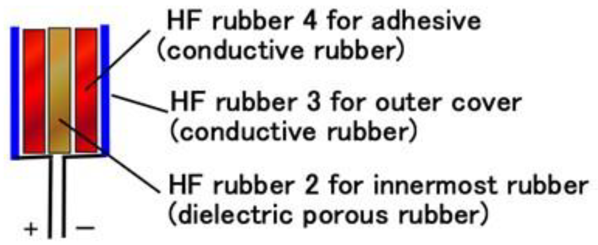
2. Materials
- a.
- Novel solidification of a rubber: rubber including water can be vulcanized by the application of an electric field so that the molecules of the rubber can be crosslinked, which is different from ordinary vulcanization with sulfur; the involvement of water makes solidification possible by mixing NR or CR rubber.
- b.
- Production of pores and infiltration of a liquid into the rubber: a rubber can have many pores due to electrolytic polymerization with mixing in a metallic hydrate such as Na2WO4 2H2O.
- c.
- Adhesion of the rubber to a metal: through electrolytic polymerization and the addition of water and a metallic hydrate such as Na2WO4 2H2O, we can adhere the rubber to a metal; the electric wires adhered to the sensor as electrodes to measure voltage need to adhere to the rubber to prevent them from detaching.
3. Methods
4. Results and Discussion
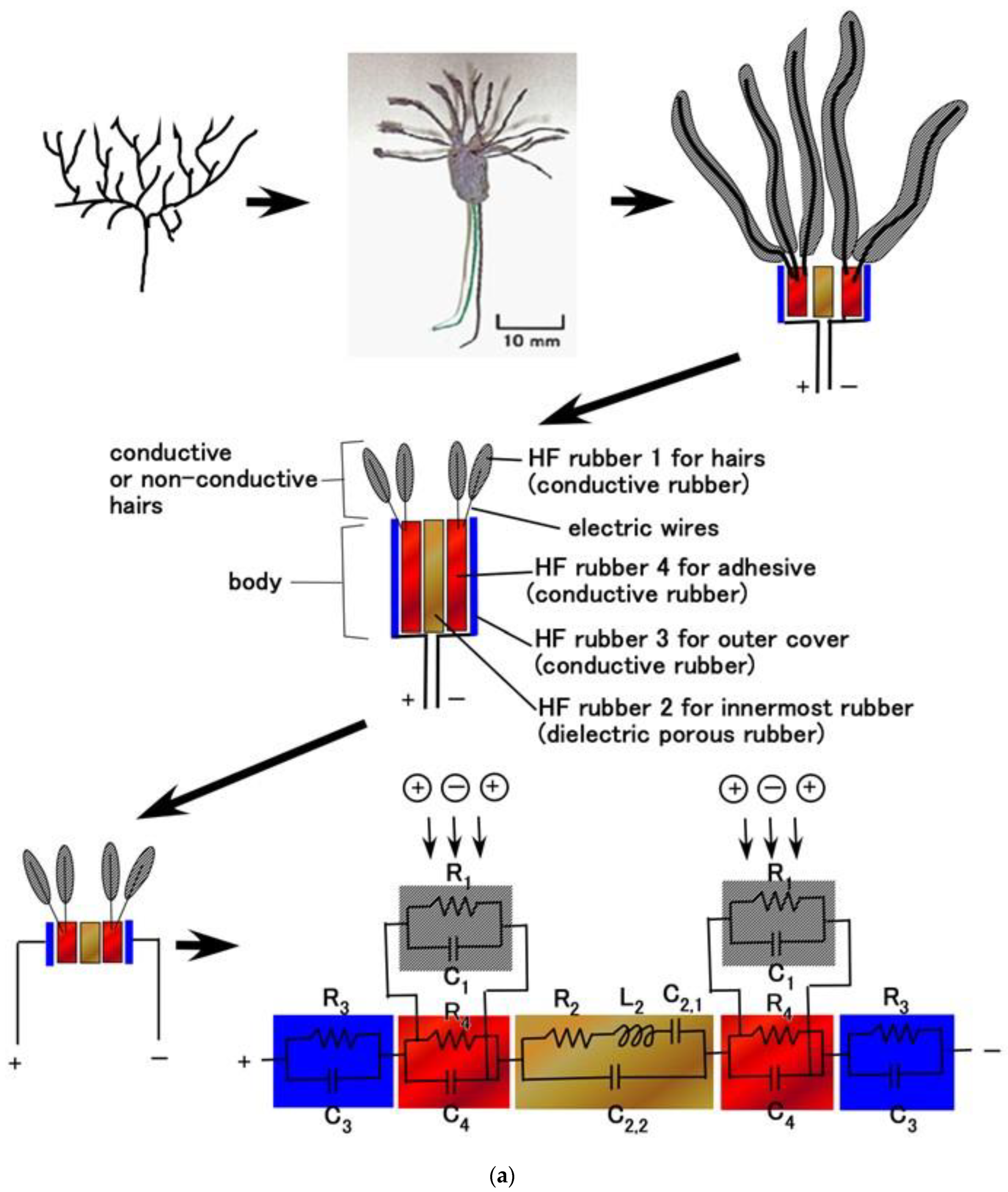
4.1. Inner Electrical Phenomena
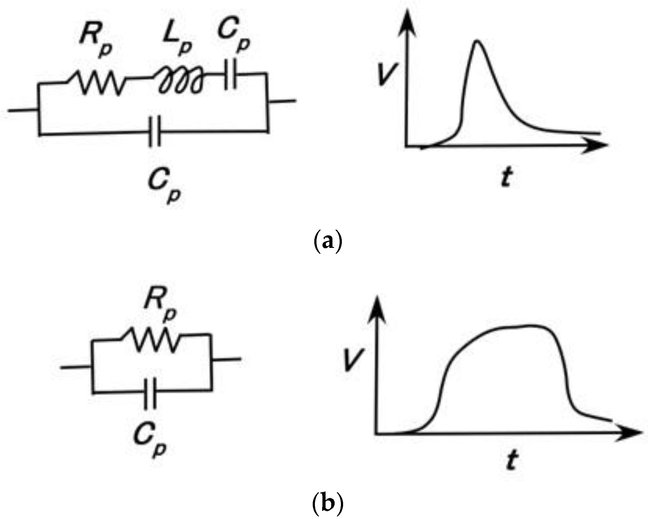
4.2. Equivalent Electric Circuit
4.3. Firing Rate
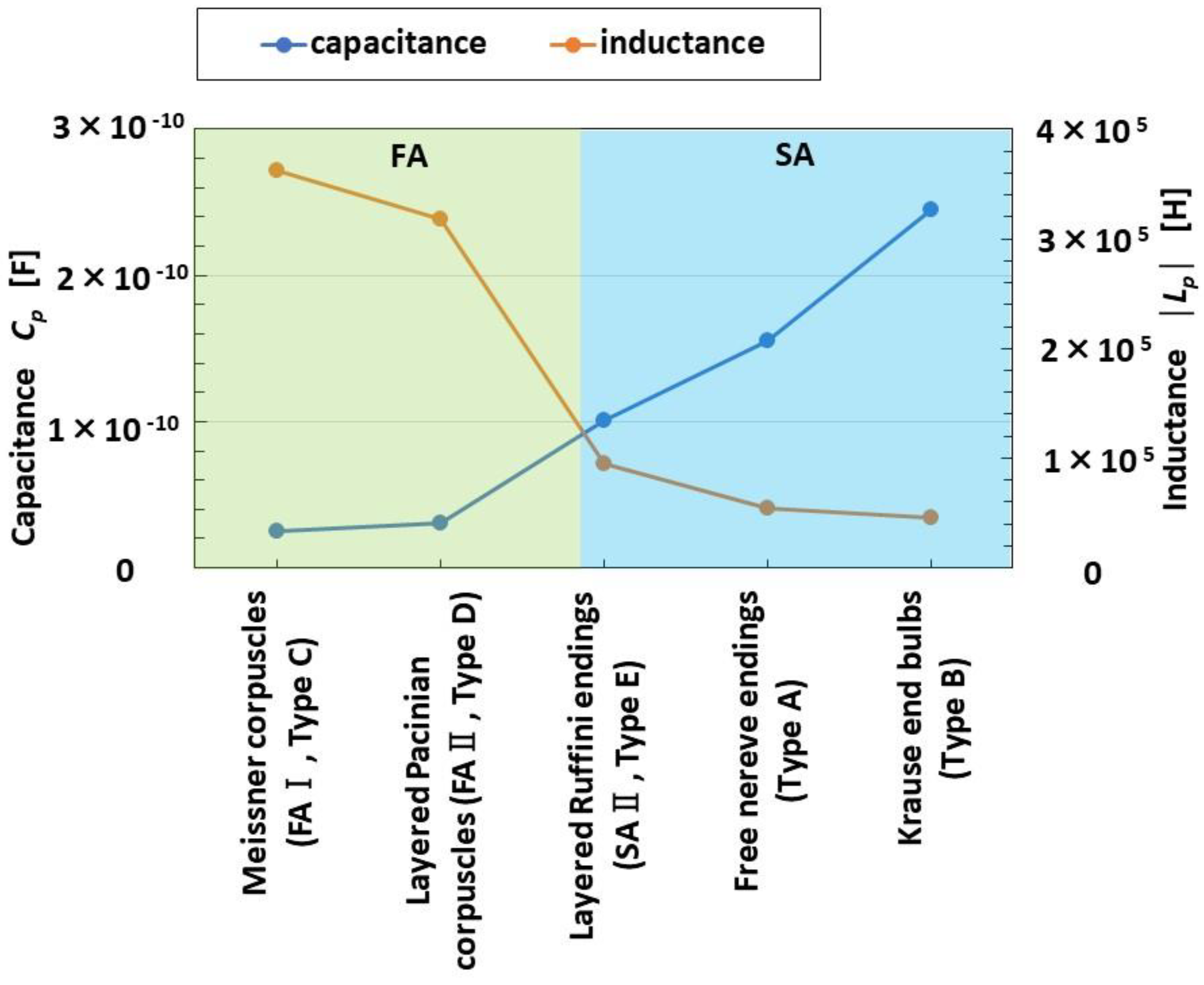
4.4. FA and SA
5. Conclusions
Funding
Institutional Review Board Statement
Informed Consent Statement
Data Availability Statement
Acknowledgments
Conflicts of Interest
Appendix A

Appendix B

Appendix C

References
- Yang, G.Z.; Bellingham, J.; Dupont, P.E.; Fischer, P.; Floridi, L.; Full, R.; Jacobstein, N.; Kumar, V.; McNutt, M.; Merrifield, R.; et al. The grand challenges of science robotics. Sci. Robot. 2018, 3, eaar7650. [Google Scholar] [CrossRef] [PubMed]
- Heng, W.; Solomon, S.; Gao, W. Flexible electronics and devices as human-machine interfaces for medical robotics. Adv. Mater. 2022, 34, 2107902. [Google Scholar] [CrossRef] [PubMed]
- Jung, Y.H.; Park, B.; Kim, J.U.; Kim, T. Bioinspired electronics for artificial sensory systems. Adv. Mater. 2019, 31, 1803637. [Google Scholar] [CrossRef] [PubMed]
- Li, S.; Bai, H.; Shepherd, R.F.; Zhao, H. Bio-inspired design and additive manufacturing of soft materials, machines, robots, and haptic interfaces. Angew. Chem. Int. Ed. 2019, 58, 11182–11204. [Google Scholar] [CrossRef] [PubMed]
- Yang, J.C.; Mun, J.; Kwon, S.Y.; Park, S.; Bao, Z.; Park, S. Electronic skin: Recent progress and future prospects for skin-attachable devices for health monitoring, robotics, and prosthetics. Adv. Mater. 2019, 31, 1904765. [Google Scholar] [CrossRef] [PubMed]
- Chortos, A.; Liu, J.; Bao, Z. Pursuing prosthetic electronic skin. Nat. Mater. 2016, 15, 937–950. [Google Scholar] [CrossRef] [PubMed]
- Munger, B.L.; Ide, C. The structure and function of cutaneous sensory receptors. Arch. Histol. Cytol. 1988, 51, 1–34. [Google Scholar] [CrossRef] [PubMed]
- French, A.S.; Torkkeli, P.H. Mechanoreceptors. In Encyclopedia of Neuroscience; Squire, L.R., Ed.; Elsevier: Amsterdam, The Netherlands, 2009; pp. 689–695. [Google Scholar]
- Hamann, W. Mammalian cutaneous mechanoreceptors. Prog. Biophys. Mol. Biol. 1995, 64, 81–104. [Google Scholar] [CrossRef] [PubMed]
- Bolanowski, S.J., Jr.; Gescheider, G.A.; Verrillo, R.T.; Checkosky, C.M. Four channels mediate the mechanical aspects of touch. J. Acoust. Soc. Am. 1988, 84, 1680–1694. [Google Scholar] [CrossRef] [PubMed]
- Chun, K.Y.; Son, Y.J.; Jeon, E.S.; Lee, S.; Han, C.S. A self-powered sensor mimicking slow- and fast-adapting cutaneous mechanoreceptors. Adv. Mater. 2018, 30, 1706299. [Google Scholar] [CrossRef] [PubMed]
- Shimada, K. Morphological conFigureuration of sensory biomedical receptors based on structures integrated by electric circuits and utilizing magnetic-responsive hybrid fluid (HF). Sensors 2022, 22, 9952. [Google Scholar] [CrossRef] [PubMed]
- Shimada, K.; Ikeda, R.; Kikura, H.; Takahashi, H. Morphological fabrication of rubber cutaneous receptors embedded in a stretchable skin-mimicking human tissue by the utilization of hybrid fluid. Sensors 2021, 21, 6834. [Google Scholar] [CrossRef] [PubMed]
- Ladhar, A.; Arous, M.; Kaddami, H.; Raihane, M.; Kallel, A.; Graca, M.P.F.; Costa, L.C. AC and DC electrical conductivity in natural rubber/nanofibrillated cellulose nanocomposites. J. Mol. Liq. 2015, 209, 272–279. [Google Scholar] [CrossRef]
- Ladhar, A.; Arous, M.; Kaddami, H.; Raihane, M.; Lahcini, M.; Kallel, A.; Graca, M.P.F.; Costa, L.C. Dielectric relaxation studies on nanocomposites of rubber with nanofibrillated cellulose. J. Non-Crys. Solids 2013, 378, 39–44. [Google Scholar] [CrossRef]
- Wang, Q.; Fan, C.; Gui, Y.; Zhang, L.; Zhang, J.; Sun, L.; Wang, K.; Han, Z. Engineered mechanosensors inspired by biological mechanosensilla. Adv. Mater. 2021, 6, 2100352. [Google Scholar] [CrossRef]
- Tiwana, M.I.; Redmond, S.J.; Lovell, N.H. A review of tactile sensing technologies with applications in biomedical engineering. Sens. Actuators A Phys. 2012, 179, 17–31. [Google Scholar] [CrossRef]
- Tomar, R. Review: Methods of firing rate estimation. BioSystems 2019, 183, 103980. [Google Scholar] [CrossRef] [PubMed]
- Nezhad, N.; Amiri, M.; Falotico, E.; Laschi, C. A digital hardware realization for spiking model of cutaneous mechanoreceptor. Fron. Neuro. 2018, 12, 322. [Google Scholar] [CrossRef]


Disclaimer/Publisher’s Note: The statements, opinions and data contained in all publications are solely those of the individual author(s) and contributor(s) and not of MDPI and/or the editor(s). MDPI and/or the editor(s) disclaim responsibility for any injury to people or property resulting from any ideas, methods, instructions or products referred to in the content. |
© 2023 by the author. Licensee MDPI, Basel, Switzerland. This article is an open access article distributed under the terms and conditions of the Creative Commons Attribution (CC BY) license (https://creativecommons.org/licenses/by/4.0/).
Share and Cite
Shimada, K. Estimation of Fast and Slow Adaptions in the Tactile Sensation of Mechanoreceptors Mimicked by Hybrid Fluid (HF) Rubber with Equivalent Electric Circuits and Properties. Sensors 2023, 23, 1327. https://doi.org/10.3390/s23031327
Shimada K. Estimation of Fast and Slow Adaptions in the Tactile Sensation of Mechanoreceptors Mimicked by Hybrid Fluid (HF) Rubber with Equivalent Electric Circuits and Properties. Sensors. 2023; 23(3):1327. https://doi.org/10.3390/s23031327
Chicago/Turabian StyleShimada, Kunio. 2023. "Estimation of Fast and Slow Adaptions in the Tactile Sensation of Mechanoreceptors Mimicked by Hybrid Fluid (HF) Rubber with Equivalent Electric Circuits and Properties" Sensors 23, no. 3: 1327. https://doi.org/10.3390/s23031327
APA StyleShimada, K. (2023). Estimation of Fast and Slow Adaptions in the Tactile Sensation of Mechanoreceptors Mimicked by Hybrid Fluid (HF) Rubber with Equivalent Electric Circuits and Properties. Sensors, 23(3), 1327. https://doi.org/10.3390/s23031327