Abstract
Nowadays, the study of the gait by analyzing the distribution of plantar pressure is a well-established technique. The use of intelligent insoles allows real-time monitoring of the user. Thus, collecting and analyzing information is a more accurate process than consultations in so-called gait laboratories. Most of the previous published studies consider the composition and operation of these insoles based on resistive sensors. However, the use of capacitive sensors could provide better results, in terms of linear behavior under the pressure exerted. This behavior depends on the properties of the dielectric used. In this work, the design and implementation of an intelligent plantar insole composed of capacitive sensors is proposed. The dielectric used is a polydimethylsiloxane (PDMS)-based composition. The sensorized plantar insole developed achieves its purpose as a tool for collecting pressure in different areas of the sole of the foot. The fundamentals and details of the composition, manufacture, and implementation of the insole and the system used to collect data, as well as the data samples, are shown. Finally, a comparison of the behavior of both insoles, resistive and capacitive sensor-equipped, is made. The prototype presented lays the foundation for the development of a tool to support the diagnosis of gait abnormalities.
1. Introduction
The biomechanical analysis of footfall and the gait is research field that is attracting more attention nowadays. It is recognized as a very effective tool for dealing with various issues associated with the march. On the one hand, these tools can be found in sports for performance analysis and feature optimization [1,2,3]. On the other hand, on the clinical side, it is used to diagnose pathologies and physical or behavioral abnormalities [4,5], as well as to monitor rehabilitation and rectification processes [6,7].
The lower limbs are the ones that suffer more during the movement of a person. Thus, they are prone to numerous diseases. With the increase in life expectancy and the ageing of the population, there are increasing numbers of cases of pain and pathologies that affect these parts of the musculoskeletal system [8]. However, the appearance of these problems is not only concentrated in the elderly population. According to [9], around 24% of people over 45 years report frequent foot pain. Many of these disorders arise as a result of having some physical abnormality not treated efficiently, such as flat feet, which gradually affects the rest of the musculoskeletal system. Another possible cause of the appearance of chronic pathologies of this nature is associated with daily bad walking habits [10,11,12]. Some of these bad habits are moving with an unbalanced load with respect to the center of the spine, or having a very marked pronator or supinator gait, which deviates from safety margins, which can cause metatarsalgia [13]. All of these anomalies and bad habits require analysis to identify them and the design of an action plan to solve them. Furthermore, the progress of this action plan has to be analyzed over time.
Gait abnormalities associated with specific clinical cases, such as the appearance of tumors, Parkinson’s disease, or cerebral palsy, are also common, according to [14]. In order to prevent severe damage, each of these cases should be analyzed and monitored, over time, specifically. The tracking of each case separately is a complex task.
The methods to analyze the gait include visual observation. This has a limited precision and can change between individual medical professionals (clinician). Therefore, visual observation is often complemented by standardized tests [15], which can be performed with different measurement equipment. The most frequent electronic measurement resources are located in specialized rooms, called Gait Labs [16]. The measurement systems of these rooms include cameras and sensor platforms that capture the trajectory and distribution of pressure on the sole of the foot. The information collected is then analyzed to identify patterns and calculate important characteristics in the clinic. Although these types of instruments are generally accurate, they cause physical and cognitive conditioning in the patient during the collection of the data, as they focus on performing tests, for which there may be bias in the measurement [17]. Furthermore, creating this type of room is economically expensive, and the information collected is limited to the time of the testing session [18].
The latest alternatives to the previously described approach are focused on the integration of measurement sensors into wearable devices. These devices can record or transmit data while the user performs daily activities [19]. This approach allows continuous analysis while distancing the user from the data-collection process. The method to collect the maximum amount of data of the footprint, static or while walking, is by recording the pressure distribution of the different regions of the foot. There are several studios and commercial solutions which have created specialized footwear for this purpose [20]. Resistive sensors are widely used because of their low cost and ease of implementation. However, they have a very abrupt response when exposed to pressure, which makes it difficult to extract precise information from the different regions of the foot [21]. Another alternative is the use of capacitive sensors. The effectiveness of this alternative depends largely on the type of materials used to fabricate the sensors. The materials must be plastic enough to allow an easy deformation but, at the same time, have the ability to return to their original decompressed state. Another requirement to address is a linear behavior between the deformation and reversion to the original shape. This is needed to achieve pressure measurements with higher resolution.
Another important feature in this kind of footwear is the distribution of the sensors in the insole. Simple solutions place sensors in the areas where most pressure is usually exerted, that is, in the area where metatarsals and phalanges join the foot, in the most distal area, and in the heel [22,23]. However, this may not be sufficient to analyze pathological cases. Adopting a contrasting perspective, some designs use a mesh of sensors which are evenly distributed throughout the insole [24,25]. These solutions achieve higher resolutions. However, the device is more complex, since it has to provide electronic resources and computational logic capable of managing the connection and reading the data from each sensor. This complexity affects the collection times, the energy autonomy time, and the device cost. A compromise solution may be the most advantageous: distributing a series of sensors in regions where pressure is usually exerted but also covering, to a lesser extent, regions of the sole of the foot where applying more pressure than appropriate reveals pathological cases or anomalies.
This paper presents the design and characterization of insoles to measure plantar pressure composed of 12 capacitive sensors for each foot. The novelties of the manuscript are: (1) The poly(dimethylsiloxane) (PDMS) material used as dielectric with an additional shock-absorbing role. The features of the material allow reversible deformation when subjected to pressure, providing high resolution in terms of data collection and continuous use without breaking or yielding the insole. (2) The smart distribution of the sensors. They are placed to identify the pressure exerted in regions where normal and abnormal patterns can be identified, such as in the case of flat feet, hypersupination, or hyperpronation. (3) The reading of the sensors is carried out by means of a single integrated circuit for each insole, simplifying and reducing the time for the acquisition of measurements. (4) A complete process of the elaboration of the capacitive plantar insole is outlined; this is an alternative design to other proposals which does not require complex or expensive laboratory tools for its development.
The rest of the manuscript is organized as follows. Section 2 summarizes recent works that propose alternative capacitive insoles, as well as designs that use PDMS as a component in plantar insoles. Section 3 describes the materials used and the design of the insole, as well as the design of the system as a whole and the methodology used to characterize and analyze the system. In Section 3, the results and discussion are shown. Finally, Section 4 presents the conclusions.
2. Related Works
In the current state-of-the-art, there are already proposals for wearable systems with capacitive insoles. Commercial solutions such as Motion SCIENCE [26,27,28], for which manufacturing processes are not available for replication, are common. Other studies, less scarce, do propose their own insole design with capacitive sensors.
In the study of [29], capacitive sensors composed of a glass epoxy PCB as a conductive layer and rubber as a dielectric are proposed. Four sensors were attached to a rubber sole in its lower part to make the system. The measurement system is completed with a simple CDC of its own design, an ATMEGA8 microcontroller, and an XBEE module to send the results. The load results show a response close to linear, although with a progressive decrease in response to loads greater than 40 kg over the entire area of the insole. The rubber material used to manufacture the sensor is not specified.
Similarly to the previous study, in [30], sensors which include rubber as a dielectric layer are proposed; however, a conductive textile “W- 290-PCN” from the manufacturer A-Jin is used. The method of integrating the sensors in the plantar insole is more sophisticated: a rubber insole with grooves is made to house the conductive layer and the cables that allow the connection with the acquisition system. In this proposal, there are 10 sensors which are integrated into the insole and have to be placed in more peripheral areas because the central area is reserved for locating the connection cables for each sensor. A commercial CDC MPR121QR2, an STM32F103 microcontroller, and a bluetooth module are used as the main components of the collection and transmission system. Data on the response to different loads are not provided, but a comparison of the response to walking is made between the proposed system and another commercial F-Scan system, obtaining similar results. In this study, the composition of the gum used is also not provided.
In the work [31], an insole is presented whose sensors use a double layer of copper and an EMFIT electroactive ferroelectric film as an intermediate layer. There are eight sensors located on the insole, in positions of greatest interest based on the pressure zones of the foot during walking and treading. In the version of the referenced study, the fragments of EMFIT are glued together with the copper inside two layers of copper that cover the foot area. In a later, more sophisticated version presented in [32], EVA rubber is used to adhere the sensors. The second publication presents the hardware used, consisting of FDC1004 as CDC, an LPC824 microcontroller, and a bluetooth module SPBT3.0DP2; this system is integrated into the insole itself in the area of the plantar vault. The study shows that the response is linear from loads of 600 KPa.
The study presented in [21] proposes the design of a low-cost insole, in which the sensors are made up of silver cloth as a conductor and four layers of cotton cloth. The insole consists of two layers of cotton that contain three circular-shaped sensors, which have a very high radius with which they cover the entire area of the foot. As elements of the acquisition system, there is a PCAP01 as CDC, a PIC18F25K80-I/MM microcontroller and a bluetooth module. Although it does not present a linear response of pressure with respect to capacitance, the study reveals that the derivative with respect to an initial capacitance is close to linear.
The study [33] presents a sophisticated design composed of small triangular links, each of which has twelve capacitive sensors made of copper and a silicone rubber foam to which a spray of electrically conductive silicon rubber is applied. Each of the triangles records the measurements of an AD7147 CDC controller. The measurements are sent and processed by a single controller, and sent by I2C. The performance of the system is accurate given the number of pressure sensors, a total of 280; however, the complexity of the system requires special shoes that limit portability.
This work proposes the use of PDMS as a flexible dielectric material for the development of a capacitive insole. In previous work, the plantar insole proposals use PDMS as a cover for piezo-resistive sensors. In [34], a simple design is presented that does not require complex tools for its elaboration or welding process, but no acquisition system is presented and the difficulty of connecting the outputs, which are distributed along one edge of the insole, is not resolved. In [35], PDMS is also used, creating a composition with multiwalled carbon nanotube (MWCNT) to make a piezo-resistive sensor; the insole design in this case is complex, requiring sophisticated printing machines. In this study, no complete acquisition system is presented either. In work [36], the authosr again use a composition of PDMS and MWCNT to cover the electrodes, creating piezoresistive sensors. A plantar insole of seven sensors is proposed, which is arranged on a layer of PET substrate, and a mold is used to create the layer of a PDMS-MWCNT composite in the place where the electrodes are located. The manufacturing process of the PET substrate layer with the electrodes is not detailed.
The proposal of this work consists of a complete system in which PDMS is used as a dielectric intermediate layer and copper is used as a conductor to develop capacitive sensors. PDMS is not only distributed in the location of the sensors but also covers the rest of the area of the plantar insole, so it has the same composition and thickness, improving ergonomics, and without conditioning the distribution of pressure during footsteps due to the presence of different materials on the surface of the insole. The way to manufacture this layer is from a mold, which can be customized without the need to alter the manufacturing process, providing the possibility of creating different plantar-insole sizes, and changing the size, shape, and distribution of the sensors.
Second, building on the insoles developed in this work, future work is intended to redirect the studies of footprint analysis begun by [37,38], in which machine learning is used to identify gait pathologies with resistive insoles. With current improvements in hardware performance and communication technologies, advances in the development of wearable IoT devices for health monitoring have been increasing. In the context
of body mechanics analysis, this includes applications ranging from stress detection [39] to identifying biomechanical habits that pose a risk to health [40]. With the use of capacitive insoles and the use of PDMS as a dielectric, given its mechanical qualities, it is hoped to achieve better resolution in the data than those obtained with resistive sensors, allowing one to take advantage of the potential of advanced machine-learning algorithms, which can identify subtle features and are tolerant to noise.
3. Materials and Methods
3.1. Capacitive Insole Composition and Materials
Each of the sensors in the insole consists of two electrodes separated by an insulating dielectric. This dielectric must be flexible enough to permit the pressure of the foot to cause a deformation in the dielectric, which eventually changes the distance between the two electrodes. The capacitance variation with respect to distance can be computed using Equation (1).
where C is the capacitance of the capacitor (F), is the dielectric constant (2.3–2.8 for PDMS [41]), is the vacuum permittivity (8.854 × 10⁻¹² F/m), A is the area (m2) and d is the distance between plates (m).
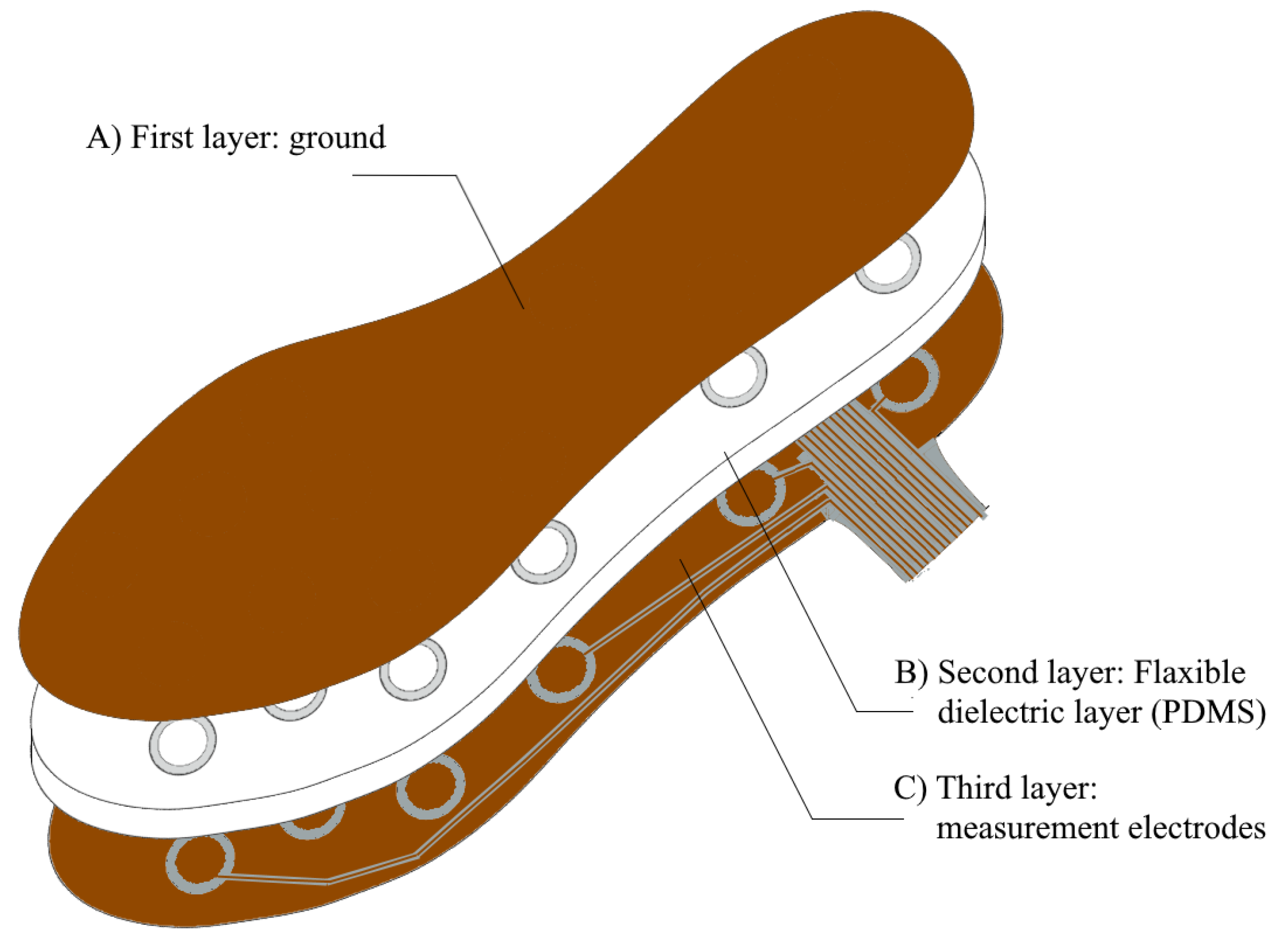
The plantar insole proposed in this paper relates the distance between several electrodes with the ground. Thus, an intermediate material must be included. For this reason, the capacitive insole designed is composed of several layers (see Figure 1): (1) the first layer is the ground of each of the sensors which is common to all of them; (2) a flexible and thick-enough second layer with the insulating element which acts as a dielectric and (3) the last layer with all the measurement electrodes placed at specific strategic points.
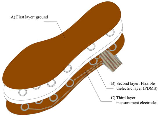
Figure 1.
Scheme of main layers that make up the proposed plantar insole.
PDM-Based Dielectric Layer
The three materials most commonly used in the literature as dielectrics in capacitive insoles are: PDMS, PVC and Ecoflex. PDMS is the material with the best pressure measurement range, the best sensitivity and the best durability [42,43]. PDMS is a type of silicon-based material which is transparent. Its mechanical properties depend on its fabrication process. Its viscoelastic behavior is the reason why it has been frequently used in applications such as the one presented in this paper. Its properties as a dielectric make it an excellent choice for the purpose of this insole design [44].
The thickness of the insole affects not only the sensor sensitivity but also the comfort of the device. In order to select the best thickness, different tests were performed with a single sensor. For the dielectric, several PDMS cylinders with a radius of 15 mm and different heights (2, 3, 4 and 5 mm) were made. Cylinders were placed between two copper electrodes of the same radius to create the capacitive pressure sensors. Since the size of these cylinders is small, the pressure performance study was performed using a screw and connecting the electrodes to a development board which includes a CDC AC7146. With each 1/4 turn of the screw, the pressure on the device increased by 17 KPa, reaching a final pressure of 119 KPa. After several pressure tests, the sensitivity results can be seen in Table 1. To calculate the sensitivity, the applied pressure is related to the measured capacitance; the slope of this curve provides the sensor sensitivity.

Table 1.
Sensitivity values and range for cylinders.
Only the 2 mm sensor broke under a pressure of 85 KPa because of its thickness. Therefore, it was decided to use the 3 mm sensor which has a very similar sensitivity to the previous one and avoids the breakdown of the device. For this reason, a thickness of 3 mm was selected. It is considered sufficiently comfortable to be used as a insole and it provides an adequate sensitivity.
3.2. Sensors Distribution
The location of the sensors is designed to cover the entire sole of the foot but specifically consider the areas that provide more information. According to [45], the areas of the sole of feet that provide more information are those where the metatarsal bones and the proximal phalanges are located. Another area where a wider pressure is exerted is where the calcaneus and the talus bone sit, which mainly make up the heel. By analyzing the load distribution in these areas, medical professionals can identify and monitor pathologies such as Hallux abducto valgus (HAV) deformities [46] or hammertoes [47]. The remaining covered areas correspond to the area where the medial and distal phalanges rest and where the so-called plantar arch or vault is located. The information collected in these areas complements the information required to analyze common pathologies such as pronation and supination. Furthermore, a lower or higher pressure identified in the area occupied by the plantar vault is associated with deformities such as pes cavus or flat feet [48,49].
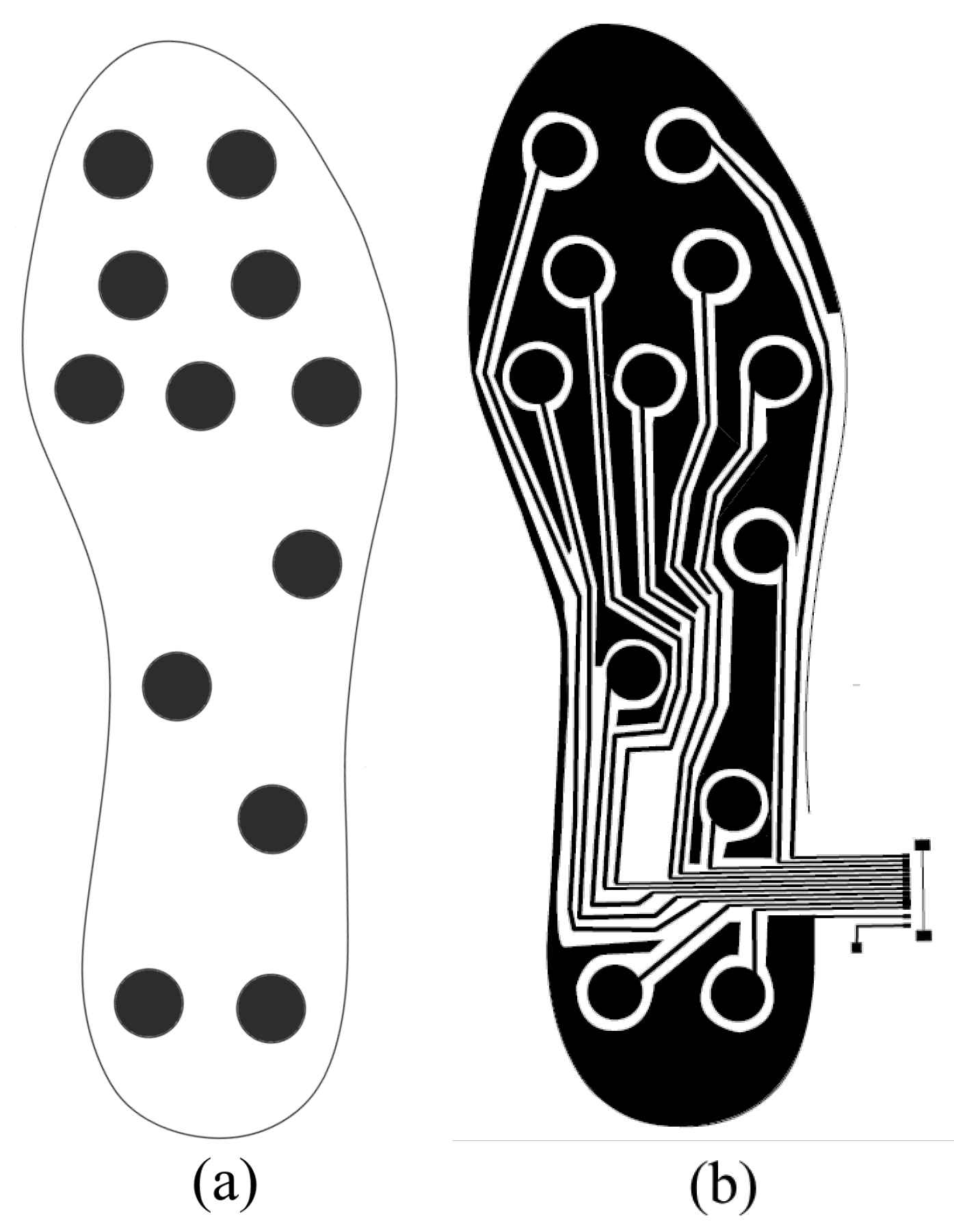
Considering the works mentioned, the final location of the sensors in the insole is shown in Figure 2. Twelve sensors are used, five located in the metatarsal and proximal phalanges area, two in the heel area, two in the medial and distal phalanges area and three in the area of the plantar vault. This distribution is similar to the one considered in previous works [31,50].

Figure 2.
(a) Location of the sensors in the proposed capacitive insole. (b) Layout of the layer with the electrodes on the capacitive plantar insole.
It is important to note that to ensure that the performance of the sensors is not affected by changes in the curvature of the plantar insole, in the design of the dielectric layer we separated the part where each sensor is located with a circular groove, 3mm thick in its circumference.
3.3. System Design
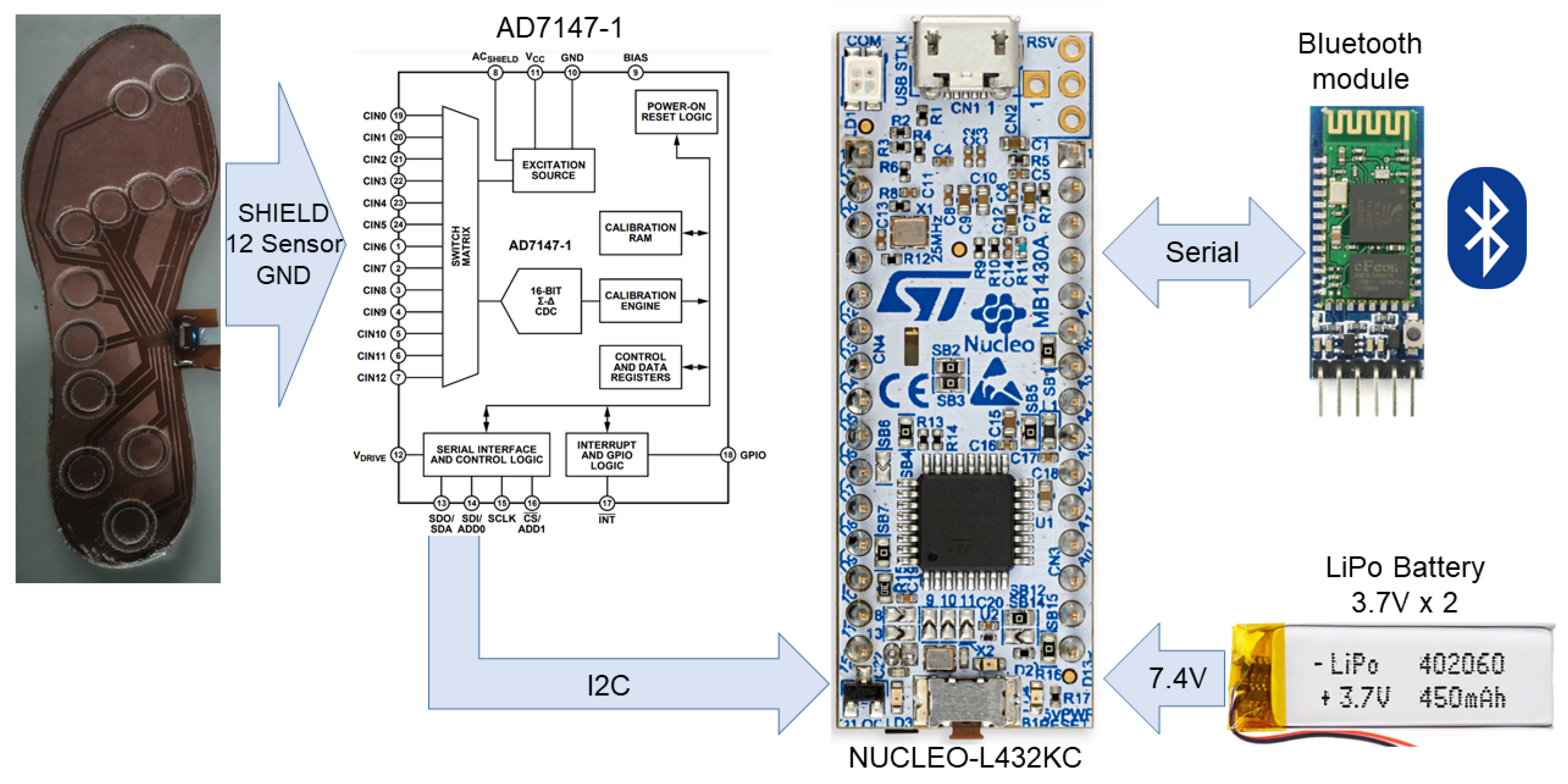
The system to obtain the samples, from the developed capacitive insole designed, is shown in Figure 3. The developed insole is connected to an AD7147-1 controller, a programmable chip equipped with a capacitance to digital converter (CDC) and an on-chip environmental calibration. This chip has an interface compatible with , which is used to set the configuration and to manage the system through an ultra-low power microcontroller (STM32L432KC) of the STM32L series with Arm Cortex-M4 MCU. The system also includes a bluetooth module which allows the user to transmit the data collected and is managed by the microcontroller and battery-power outlets.
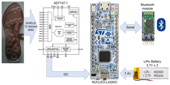
Figure 3.
Block diagram of the main components of the plantar insole system.
Additionally, to record and further analyze the data collected and sent by the system during the study, a support application was developed. The following sections explain, in detail, the features and tasks performed by each component of the system.
3.3.1. Embedded Controller System
The read process performed by the AD7147-1 controller is designed to iterate through a series of sequential steps, which are called stages. It can be configured to up to 12 stages. Each stage can be custom configured to measure the capacitance between two sensors or between a sensor and the ground layer. For our purpose, twelve stages were configured. In each of them, a capacitance reading of each sensor is obtained with respect to the common ground layer of the plantar insole. The value obtained at each stage is stored in a specific stage register. At the end of each iteration, i.e., once all the configured readings have been carried out, the AD7147 notifies the reading iteration of this completion through interrupts.
The STM32L432KC microcontroller is the component that performs the stage configuration of the integrated CDC controller. It is also in charge of accessing the internal registers of the AD7147-1 to obtain samples read from the plantar insole. The reading process is performed once all the reading stages are completed by the CDC controller.
3.3.2. Application
The developed application receives the data recorded periodically by the measurement system through bluetooth. The values obtained from each of the sensors included in the insole are shown in streaming using a graphical interface. Additionally, at the request of the user, the application can store values taken from each sensor individually, calculated from the average of a sample set, in order to eliminate fluctuations. This functionality enables the collection of data in specific tests of this work whose objective is to analyze the behavior of the sensors when subjected to a certain weight, with different plantar postures or gait stages.
3.4. Capacitive Plantar Insole Analysis
The main objective of this work is to design a system that allows high precision in the measurements recorded during walking while using the capacitive sensors insole. A comparison of the response of the plantar insole designed in this study with an insole whose sensors are resistive, specifically force-sensitive sensors FSRTM 400 sensors, is made to check if the system presented achieves higher resolution. The FSR plantar insole used for the comparison was developed and analyzed in [37,38]. It was designed to identify common gait abnormalities, i.e., pronation and supination, and some common anomalies to a degree that may be dangerous to the user or pathological. In contrast, in this paper, the objective is to design a system which supports the identification of a greater variety of pathologies.
To analyze the behavior of the plantar insole with respect to the force exerted under controlled conditions, a set of calibrated weights was used. The weights were placed on top of a base, weighing approximately 1.45 g, which has an area with the same diameter of each sensor included in the insole. In this manner, the total weight of each calibrated weight is concentrated in the entire area of each sensor. This process is used to both check that a higher resolution response is achieved when the weight is exerted, thanks to the use of the PDMS-based capacitive sensors, and obtain values that allow the individual calibration of each one of the sensors included in the insole.
The analysis of the system continues with the assessment of the response when a user is already using it to register the march. For this, a capacitive and resistive insole of each size were used. The user wearing the insole was asked to walk at a calm pace while the values acquired by the system were recorded. Observation under these conditions allowed the identification of limitations of each insole in a context closer to a real situation.
4. Results and Discussion
4.1. System Development
In this section, the prototype development process is described. Details of the implementation of the capacitive plantar and acshield insole are given. The latter component serves as a motherboard to connect the elements that make up the complete measurement system.
4.1.1. Fabrication Process of the Plantar Insole
In order to fabricate the PDMS layer, a methacrylate mold was made with the desired shape. Then, the PDMS layer was poured for curing. A laser cutter (Epilog Laser Helix 50 W) was used to cut the methacrylate pieces. All mold pieces were obtained by cutting 150 × 300 mm methacrylate sheets. The mold was made up of a base, a border to prevent PDMS leakage and twelve concentric circles (with radius of 9.5 and 7.5 mm and height of 1 mm) placed where the measurement electrodes were superimposed. This gives the shape of the capacitive pressure sensor in these areas of the insole.
The fabrication process of the PDMS needed 50 g of PDMS with 5 g of curing agent (since the ratio should be 10:1). The mixture was degassed in a vacuum chamber and poured into the insole mold. The cure was carried out in an oven, previously preheated to the same temperature, for one hour at 80 °C. Once it was cured, the PDMS could be carefully removed from the mold using a flat spatula to avoid breakage.
The fabrication process of the measurement electrodes needed flexible PCBs which consist of 35 μm copper on a Kapton substrate (AN10, CIF). The first step was to clean with acetone and isopropanol. After drying, photoresist (Positiv20, Kontatkt Chemie) was deposited on the copper layer by spraying at 30 cm and at an angle of . The photoresist was cured in the oven for 15 min at 80 °C. An acetate-based photolith film was used to print the shape shown in Figure 2b. This shape included the electrodes, tracks and ground fields that could be connected to the ACShield pin. This film was placed over the photoresist. A blackening spray (Black Covering, Abezeta) was applied to the photolith to prevent the penetration of UV light. With the photolith film aligned on the photoresist, they were placed in the UV lamp (300-245, LPKF) for 90 s.
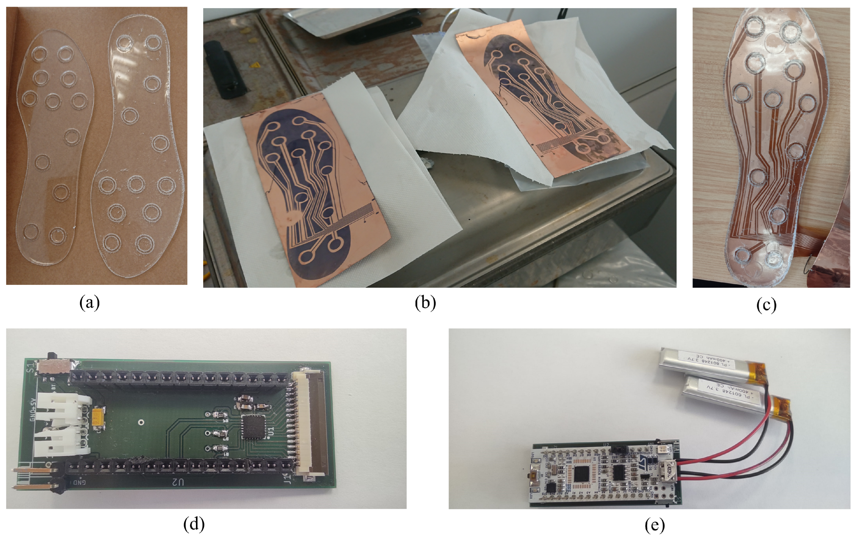
The development of the photoresist was carried out by placing it for 3 min in a tray with 3.5 g of caustic soda dissolved in 500 mL of water and gently agitated. For chemical etching, a solution of 110 vol. hydrogen peroxide (20%), hydrochloric acid (20%) and water (60%) was used. The flexible PCB was introduced into the solution until the undesired copper was removed. Electrical continuity tests were performed to ensure that there were no defects. Finally, it was cut to the shape of the insole. The result of the different components can be seen in Figure 4.
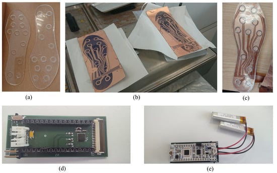
Figure 4.
Prototype components: (a) PDM-based dielectric layer; (b) flexible PCB with remaining photoresist ink, prior to copper-dissolution step; (c) the insole with three layers finished, prior to fixing them with Kapton; (d) ACShield built to house the CDC Controller Ad7147-1 and to connect both plantar insole, batteries, bluetooth and MCU to the whole system; (e) ACShield with MCU and batteries connected.
Compared to other recent studies presenting a full capacitive template design, the described manufacturing processes require the use of more complex tools, with the exception of [32], which does not solve the problem of connecting the insole to a recording system, and [34], which has a simpler design and low life cycle due to material used. Additionally, the more complex tools used in the manufacturing process can be substituted by others and their use may not even be necessary. The mold can be made with materials other than those used in this study. On the other hand, PDMS can be solidified without the use of an oven, at room temperature, but the process will take longer. In the same way, the use of a UV lamp is not necessary.
Finally, the ground layer consists of a copper foil bonded to a Kapton film. The copper foil was cut using a laser labeling machine (EASY 200F, SISMA). Then, the copper foil was adhered to Kapton tape, which acts as an electrical insulator and mechanical bonding. The copper foil was obtained from a 50 mm thick copper tape. This was the reason why two pieces of tape were used to make the ground layer of the insole. Both halves were electrically connected using two tin solder joints.
All of the layers described above were aligned and taped together with Kapton tape to ensure electrical insulation and fixing. Kapton is an insulating material which is known for its recurrent use in electronics because of its flexibility, resistance, and dielectric properties. Additionally, the ground layer was connected to the flexible PCB layer using the track designed for its connection to AD7147. Finally, for better performance, the electrodes were protected with a copper field around them, which was connected to the CDC controller.
The insoles were made for both feet with sizes that are close to the average for men and women. Specifically, sizes 43EU (27 cm long) and 39EU (24 cm long) were fabricated.
4.1.2. Connectivity of the System
A PCB shield was used to allocate the AD7147-1 CDC controller and connect it to all of the system components. These components are: an STM32 NUCLEO-L432C MCU, a bluetooth module, two 7.4 V LiPo batteries and the capacitive plantar insole. The connectivity details can be found in Table 2. The copper shield built around the electrodes is connected to the ACShield pin of the AD7147 integrated circuit.

Table 2.
PCB connectivity details. Each row represents a wire; if pin is written, it means that it is connected.
4.2. Insole Response Analysis
4.2.1. Calibrated Weights Response
The behavior analysis phase of the insole was performed using a set of calibrated weights of 20 g, 50 g, 100 g, 200 g, 500 g, 1 kg and 2 kg. The behavior of each capacitive sensor without the rest of the insole was checked using a circular base of the same diameter as the electrodes and placing each weight on top of it. The weight of the base is about 1.45 g (measured with a precision scale). The use of combinations of stacked weights to obtain more response values was avoided due to the flexible feature of the insole added to the small area of the base; it resulted in an unstable situation in the entire stack.
Table 3 shows the values obtained by exercising the different weights in the EU38 size insole, specifically, the right foot insole. Five repetitions were performed for each calibrated weight under the same environmental conditions. In order to achieve the same conditions for each repetition, the system was switched off and then on at the beginning of every test round.

Table 3.
Plantar insole— foot size 38 (24 cm).
In Table 3, it can be seen that the increase in capacitance value is directly proportional to the weight exerted. In some cases, particularly for this EU38 capacitive insole and the right foot, abnormal values were obtained. These outliers are associated with minor changes in the electric field of the environment close to the insole or with automatic calibration failures caused by the CDC Controller. However, these errors did not occur in subsequent measures. In any case, this event is reflected in the transparency and repeatability of the study. The CDC provides a 16-bit integer value resolution. The values are then converted to capacitance units according to the datasheet of the manufacturer.
Table 4 shows the results obtained when different weights are exerted on a capacitive EU 43 insole size. The process followed to obtain the samples is explained in Section 4.2.1. All the values obtained show the directly proportional behavior of the capacitance with respect to the exerted weight; anomalous data were not obtained.

Table 4.
Plantar insole— foot size 43 (27 cm).
As happened with the EU 38 size capacitive insole, it can be seen that the base capacitance value of each sensor is different. Three features can be mentioned to explain these differences: (1) small variations in the capacitive insole thickness, (2) the arrangement of each electrode on the flexible PCB with respect to the rest of the sensor tracks in the insole, and (3) the degree of coverage of each track by the copper plane that covers them. However, this change in the coordinates of the origin does not imply a problem in the measurement, since the values can be subtracted or normalized with low computational cost.
The comparison was made between the developed capacitive insole and the one previously introduced, which includes FSR sensors. The test conditions were the same as in the capacitive insole: the same calibrated weights and base platform were used. It is important to note that the base platform is the same despite the fact that the diameter of the FSRs that make up the resistive insole is smaller (approximately 7.62 mm). The results can be seen in Table 5.

Table 5.
Resistive plantar insole.
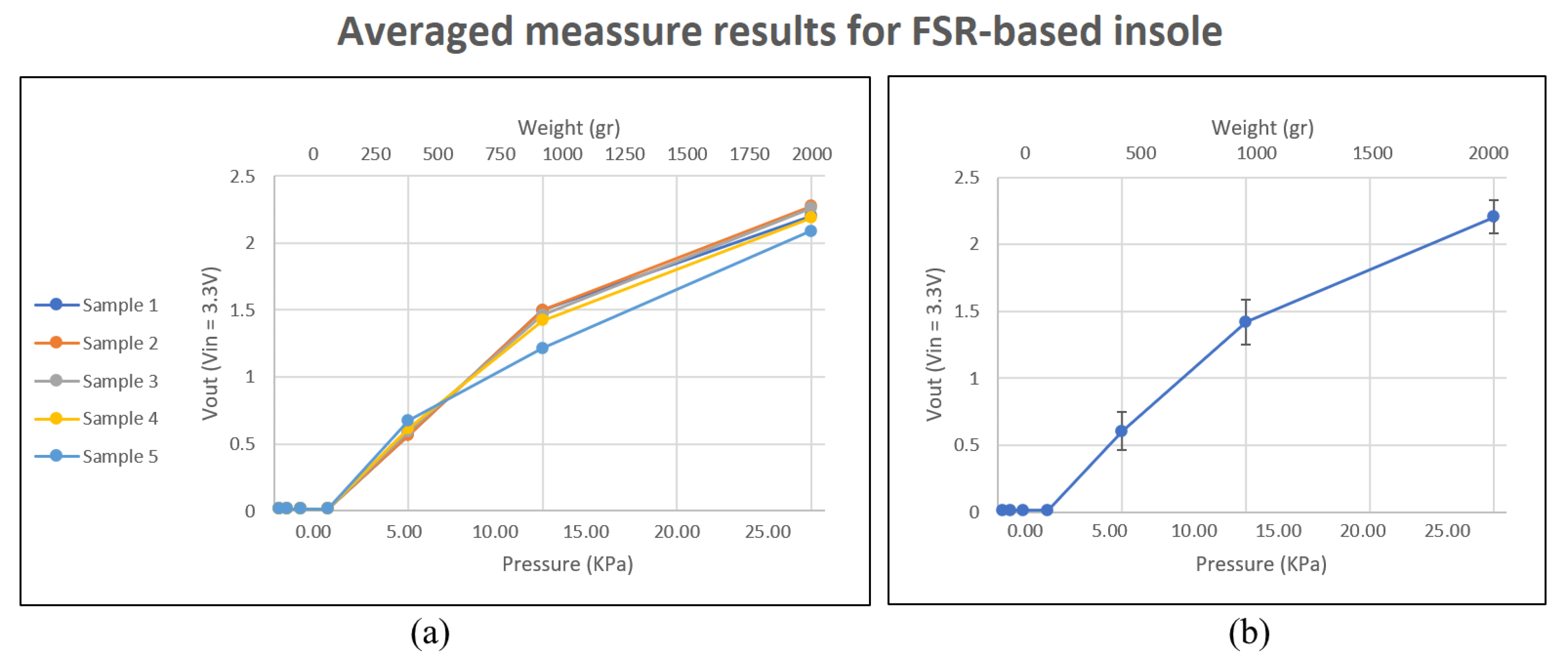
As can be seen in Table 5, the FSR sensors do not detect any change in weight up to 200 g. A response appears when a weight of 500 g is exerted on the insole. The resistive insole used in this study uses voltage dividers to acquire the values. The resolution of the ADC of the microcontroller is 12 bits and the power supply given to the sensors is 3.3 V. Table 5 shows the reverse voltage values obtained after reading the sensor, that is, 3.3 V . This inversion is performed for the sake of clarity in terms of visual comparison. It can be seen that with this simple conversion, the results obtained are also directly proportional to the weight.
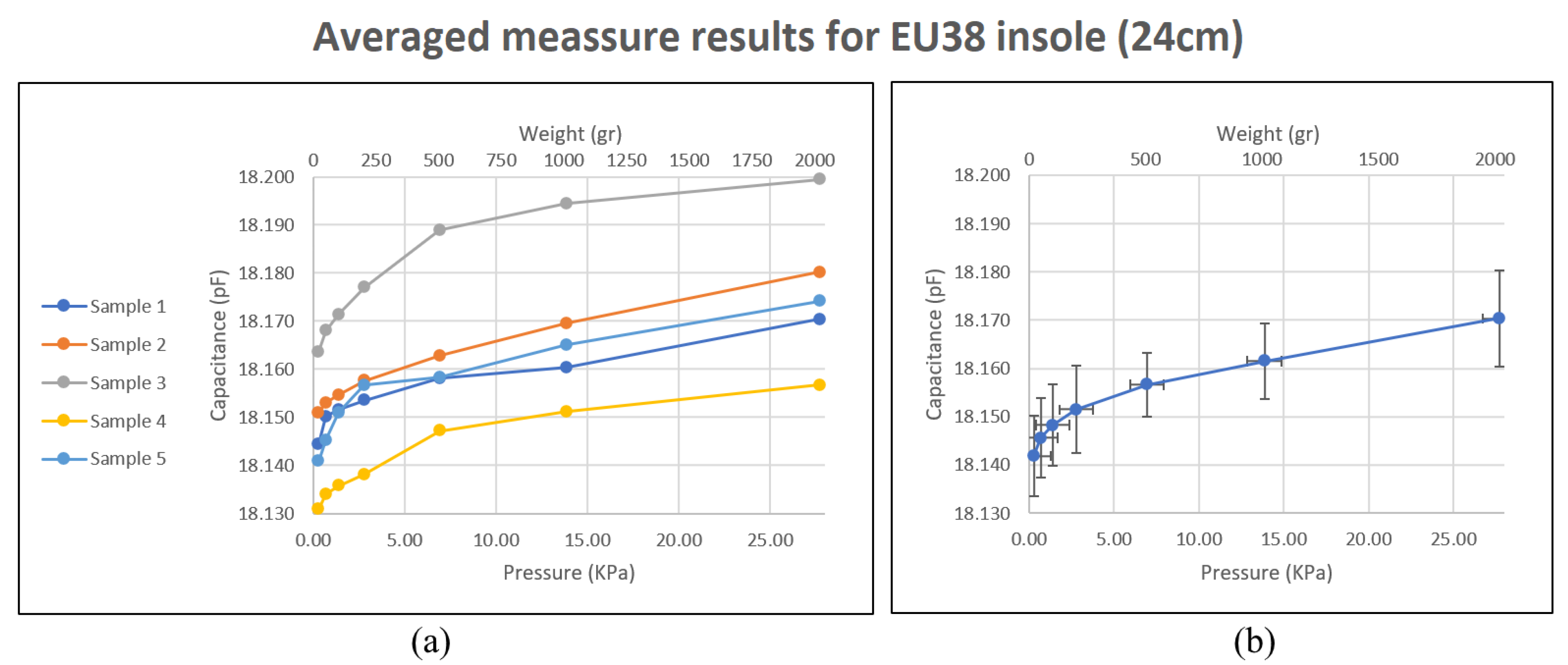
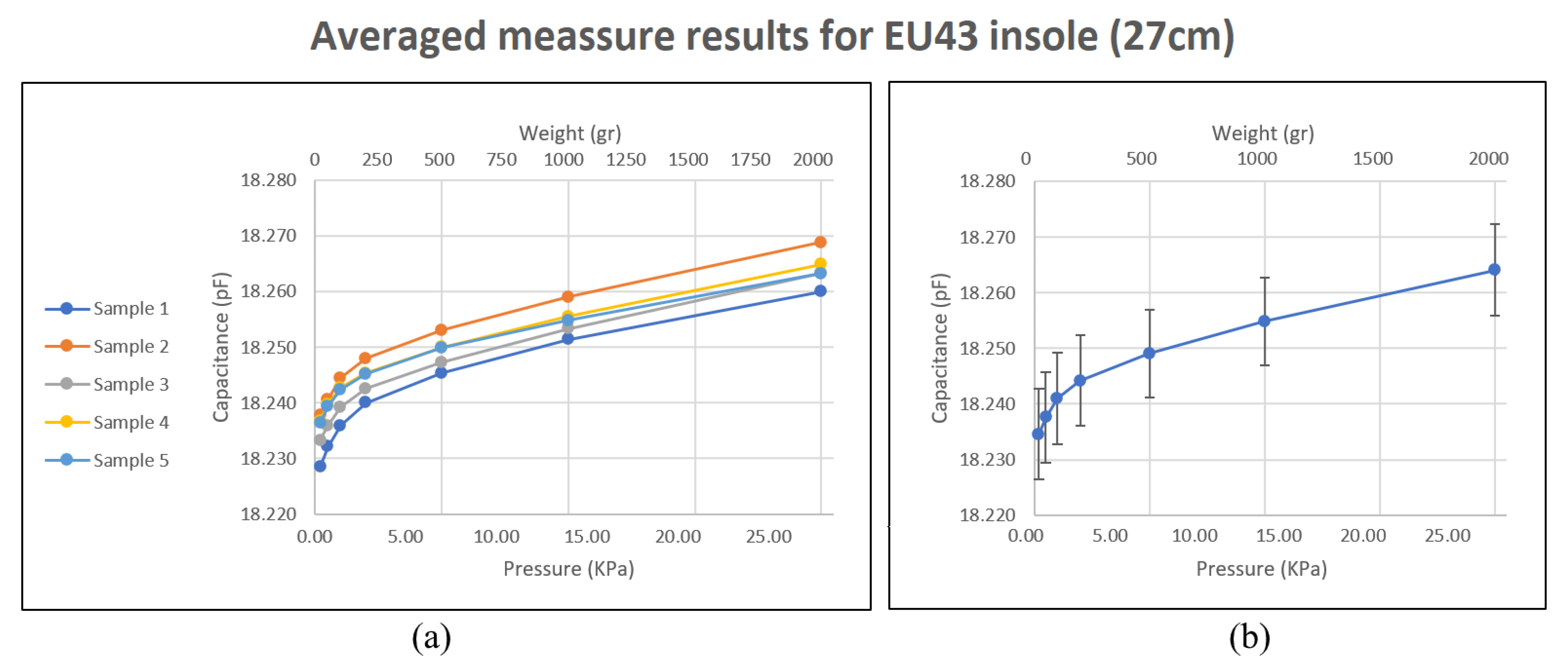
Figure 5 and Figure 6 show the average results for each repetition performed using the EU 38 size insole, as well as the combined average of all repetitions. It can be observed that for small weights the response of the sensors follows a logarithmic trend. This response may be due to the fact that the upper and lower layers of the plantar insole, that is, the shield layer and the one with the electrodes, are more separated at the beginning, so that, with small loads, the mechanical properties of the PDMS do not have much impact. However, it may also be because PDMS deforms more easily up to a given weight. However, for the highest weights, from 500 g on, the behavior can be approximated to a linear function. It should be noted that the resolution of the CDC is far from its saturation value, which is around 25 pF.
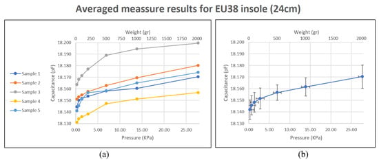
Figure 5.
Capacitive plantar insole, size 38 (24 cm). Behavior of sensors against weight in the area they occupy. (a) show the average results for each repetition performed. (b) shows the combined average of all repetitions.

Figure 6.
Capacitive plantar insole, size 43 (27 cm). Behavior of sensors against weight in the area they occupy. (a) show the average results for each repetition performed. (b) shows the combined average of all repetitions.
Figure 5b and Figure 6b show a high standard deviation, which is almost entirely due to the change in the coordinate value at the origin which is obtained with each sensor. The proportional relationship between weight and capacitance is kept in the insole, except in anomalous cases. Looking at Figure 5a and Figure 6a, a considerable change in the coordinate at the origin for the capacitance value between the different repetitions can be observed. This issue is probably due to the the temperature change of the ACShield and the MCU in the device calibration process when the tests were performed. Nevertheless, the proportional relationship between repetitions of measurement is maintained and it becomes linear with weights starting at around 500 g. This is considered appropriate given the purpose of measuring the force exerted by the footprint in different regions of the sole of the foot. This behavior is similar to that of the study presented in [32], and is closer to linear than other studies, such as [21,31], whose trends are exponential and quadratic, respectively. With other studies it is not possible to make an appropriate comparison, because they focus on analyzing the behavior of the sensors under precise loads. The study [29] reflects a linear behavior from low weights, but its design has the disadvantage of not having the sensors integrated into the insole.
The response of the plantar insole based on FSR sensors can be seen in Figure 7. An advantage of this insole is that the values obtained with each repetition are very robust, with little variation between measurements. Furthermore, the response it provides in the range from 500 g on can be assimilated into a linear function. However, given the scope of applications for which the developed system was intended, notorious disadvantages of particular relevance are encountered. Firstly, for weights lower than 200 g, a value is not obtained. This is an important limitation since pathologies related to areas of the plantar arch could not be identifiable because they are areas in which very little weight is distributed in that area of the foot’s sole. Secondly, the slope obtained in the range of 500 g to 2 kg is very high, reaching approximately 75% of the maximum resolution of the sensor in that weight range. This is a significant limitation that can prevent the identification of activities that involve maximum force on the sole of the foot. Furthermore, it could mean that it cannot make the correct measurements in users who are overweight and prone to foot injuries and pathologies.
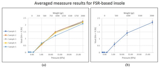
Figure 7.
Resistive plantar insole. Behavior of sensors against weight in the area they occupy. (a) show the average results for each repetition performed. (b) shows the combined average of all repetitions.
4.2.2. Insole Response with Higher Loads
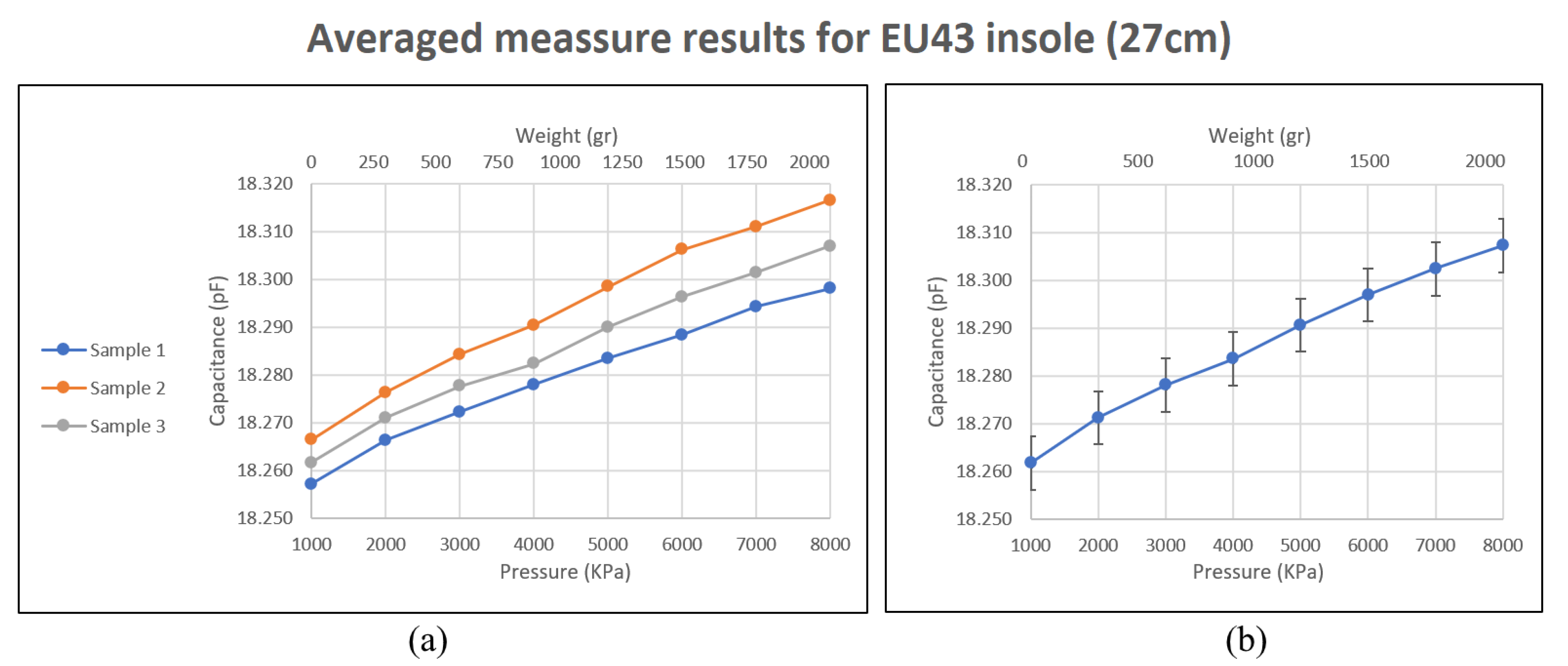
To analyze the behavior with higher loads, a screw was used. Measurements were taken from 1Kg to 8Kg. All the sensor responses were registered, but only three repetitions were carried out and using one plantar insole, specifically, the left-foot insole, size EU 43. The results obtained can be seen in Table 6. The increase in capacitance per kilogram added is small, but it follows a close-to-linear trend for all sensors. The sensitivity obtained is higher in those sensors whose bus is closest to the edge of the plantar insole. For example, the sensitivity of the s9 sensor is around 0.76 fF/KPa while that of the s5 sensor is around 0.46 fF/KPa.

Table 6.
Plantar insole—foot size 43 (27 cm)—higher loads.
Figure 8 shows the average result obtained. As indicated, the behavior of the template for these loads is close to linear. This result is consistent with the results obtained in preliminary tests of this study, and in the works [42,43]. Regarding work with capacitive plantar insoles, again, the behavior of the sensors in this study coincides with those elaborated in [29,32].

Figure 8.
Behavior of sensors against weight in the area they occupy, Using higher loads. (a) show the average results for each repetition performed. (b) shows the combined average of all repetitions.
4.2.3. Insole Response during Gait
In this section, the behavior of the insole is analyzed by obtaining data from users walking while wearing it. For the EU 43 capacitive and resistive insole test, the participant who wore them was a 31-year-old man weighing 91 kg. For the EU 38 size insole test, the participant was a 32-year-old woman weighing 65 kg. Participants were asked to walk at a leisurely pace while the developed registration application was used to collect the data received by each insole. For the resistive insole, two steps were carried out: (1) the data obtained by each sensor in the tests were used to scale the values and (2) a normalization of the values was carried out considering the maximum initial value of 3.3 V.
For the capacitive insoles, a calibration was also carried out from the values obtained in the tests with the calibrated weights. An additional step was added, consisting of partially screening the electric-field component exerted by the body itself in proximity to the sensors. This was carried out by dividing the sample recorded in a time instant by the mean of the values for that time instant of all sensors. Since all sensors were affected, all of them were used to perform the average.
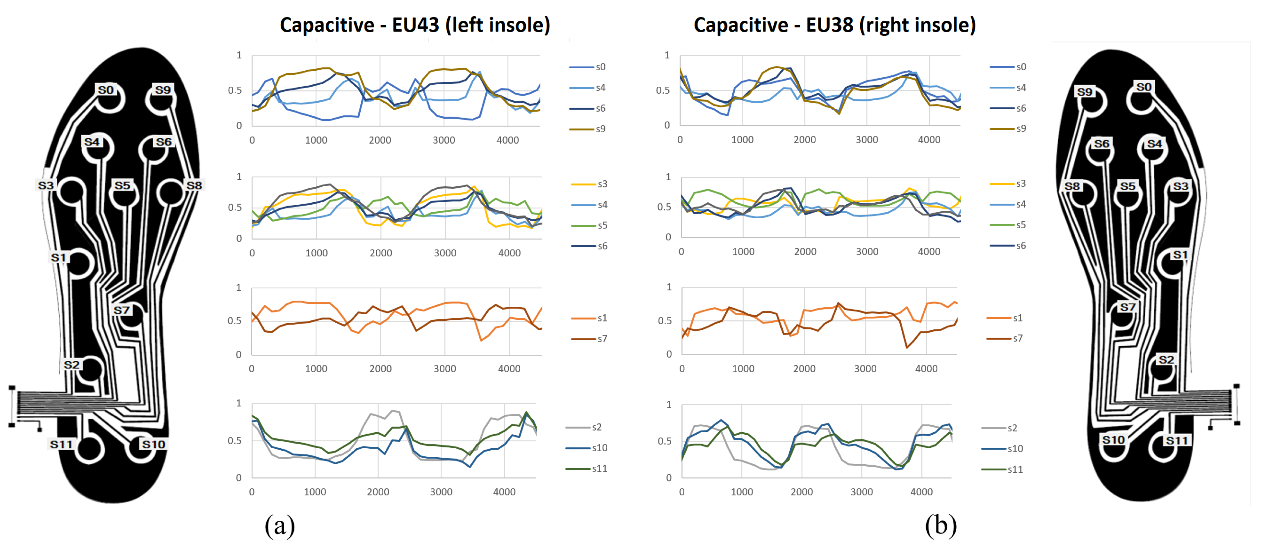
Figure 9 shows the results for the capacitive insoles. The values were normalized for an easier comparison, so the measurements have a value between 0 and 1. The values taken for the normalization of each sensor were the maximum and minimum values obtained in the entire record, plus 10% of the difference between these two values. It should be noted that this normalization is applied for better visualization in Figure 9, although it could be a valid normalization process to use them as inputs of a machine-learning model. The results can be seen in several graphs, where the signals are grouped by region, that is, where on the sole of the foot they are located. As a result, greater activity can be observed in the sensors located in the most distal zone, in the upper metatarsus and in the phalanges. In addition, the activity of the rest of the sensors can also be seen, with a set of values in the range obtained during the previous phase. There is no loss or saturation of the values.
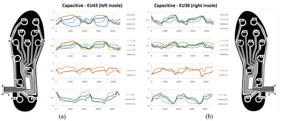
Figure 9.
Behaviour during user gait—capacitive insoles. (a) EU43 size, left insole. (b) EU38 size, right insole.
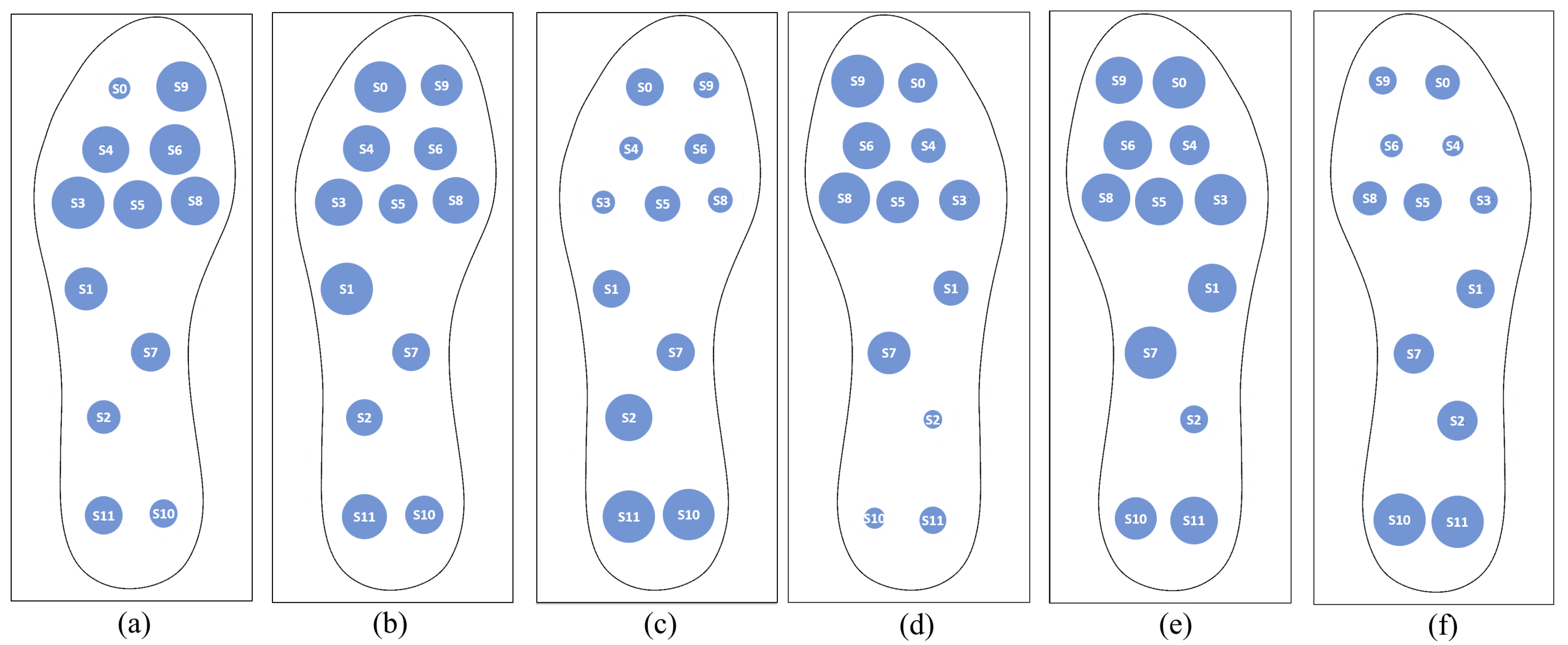
Figure 10 illustrates some distribution maps, where the responses of the insoles during different gait stages are shown. The results show that the insole responds to footsteps consistently. Although a more exhaustive analysis would be necessary to estimate the robustness of the system in the acquired data, the results show that it is possible to record data that can be used to train machine-learning models and develop a support system for monitoring and identifying pathologies.

Figure 10.
Map distribution samples obtained during different gait stages. For size EU 43 insole: (a) the forefoot is resting on the ground; (b) the whole foot is resting; (c) the hindfoot is resting. (d–f) reflects the same stages as (a–c), respectively, but with the size EU 38 insole.
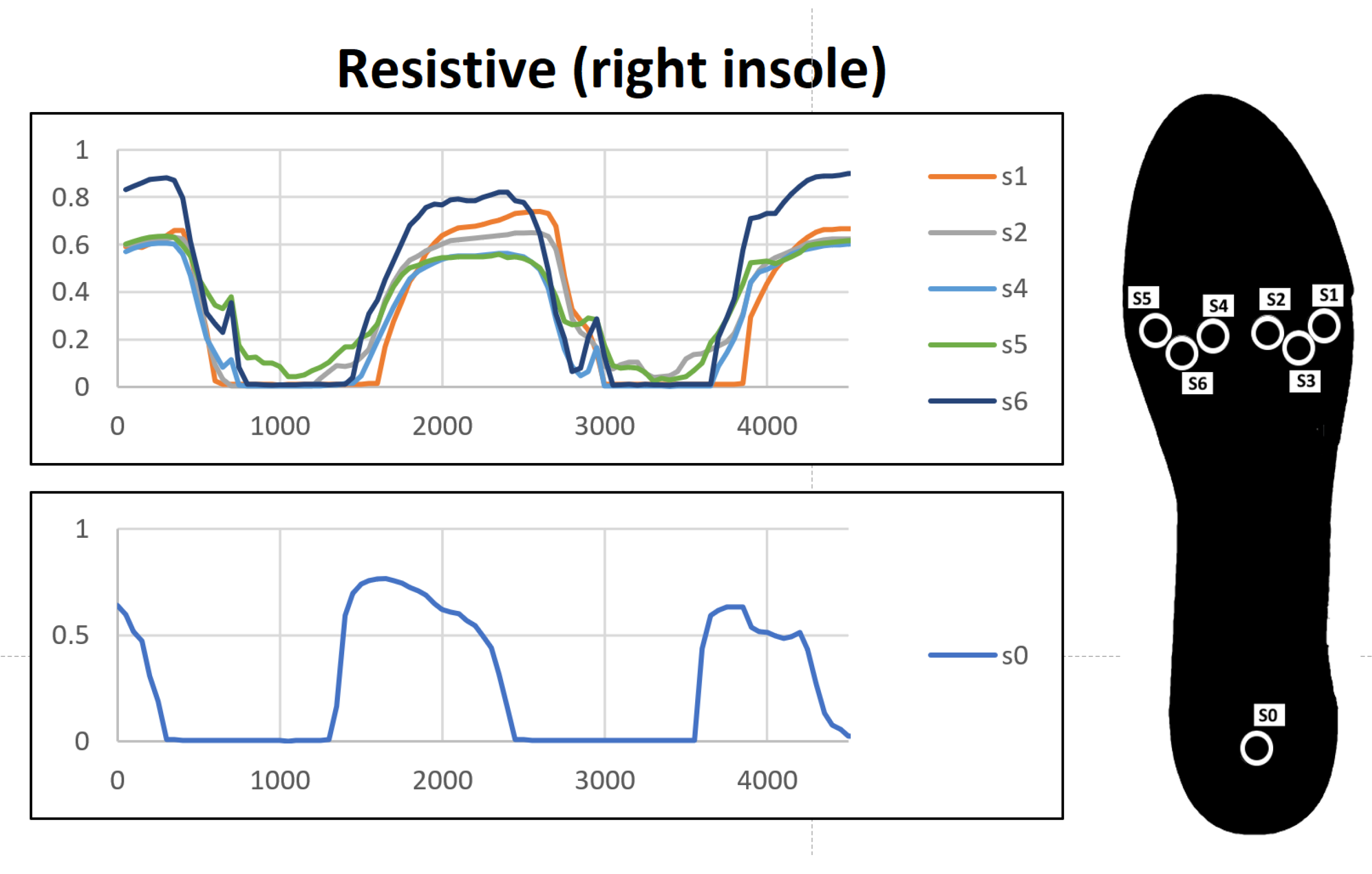
The results of the gait recording test while the user was wearing the resistive insole can be seen in Figure 11. The values obtained are more revealing and easy to observe at a glance. However, as expected, at moments in which a reduced weight is exerted, the insole does not register any response. Thus, it might lose relevant information for the identification of more subtle characteristics. Additionally, it can be seen how some sensors at specific temporal instants are very close to the saturation value. It must be taken into account that the test conditions were: walking at a leisurely gait and with a participant of a high weight given his height. However, people with gait problems may have higher weights, which would make the FSR sensors reach its saturation region, thereby limiting the measurements.
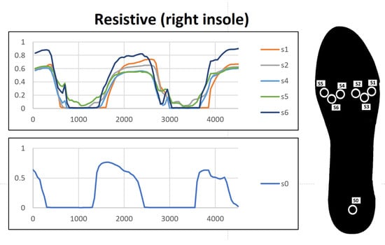
Figure 11.
Behaviour during user gait—resistive insole.
These reasons are relevant enough to choose the capacitive insole presented in this paper. Its use in anomaly identification problems will allow more precise data to be obtained and, therefore, provide more information. The additional steps needed to filter out the electric field might be the downside of the processing system. However, the use of artificial-intelligence algorithms for the identification of anomalies, given the linear nature of the disturbance, is likely to cope with this type of conditioning.
4.2.4. Response-Time Details
Regarding acquisition times, measurements with the highest decimation level of the CDC controler were performed every 37 s. However, the measurements were collected every 100 milliseconds using a sampling rate of 10 Hz. This rate is considered enough for gait monitoring and the identification of abnormalities. The sampling frequency could reach 25 Hz, without reducing the decimation, by reducing the data-transmission time. This reduction can be achieved by increasing the byte transmission rate, which has the disadvantage of higher consumption. Another possibility to reduce the transmission time is to compress the information to reduce the number of bytes that have to be transmitted by serial communication.
5. Conclusions
In this paper, a system equipped with capacitive insoles for recording anomalies in footprints was developed. To achieve the linear response of each sensor, a PDMS composition is used as the dielectric in the intermediate layer of the plantar insole. This paper shows the entire development process of the insole and the collection and delivery system. Thus, any researcher can replicate it. The proposed manufacturing process does not require the use of expensive tools. The most expensive material used is flexible PCB sheet, although this material can be replaced, for example, by using 3D printers to make flexible printed circuits.
The analysis performed reveals that capacitive sensors have advantages over resistive ones. Specifically, capacitive sensors are capable of reacting to small weights, which allows the analysis of anomalies and pathologies with more subtle characteristics. In addition, they offer a linear behavior for weights from 1Kg without saturation.
The presented design is an alternative to other capacitive insoles proposed in the literature, offering correct performance, behavior under footfall similar to studies that achieve a linear response, and totally homogeneous integration of the sensors in the plantar insole, which favors ergonomics.
The response offered by the recording system is appropriate in terms of time to identify the changes, phases, and events in the march. There is room for improvement in the transmission process and changes in decimation to perform more samples per second.
The main limitation identified in the prototype consists of the disturbance in the values due to the electric field exerted by the body. However, this disturbance can be partly removed in a simple way by performing multiplication operations. The results of the gait analysis reveal that the signal retains the gait information after the transformation. However, the search for different filtering methods could be relevant to retain information of interest for the identification of anomalies.
As a future work, the developed system will be used to record the gait of several users with pathologies or anomalies that influence gait. With the prepared data set, machine-learning models will be developed and evaluated to identify pathologies autonomously in order to develop a complete monitoring and diagnostic support system.
Author Contributions
Conceptualization: B.S.-D., F.L.-P. and A.M.-E.; Formal analysis: B.S.-D. and F.L.-P.; Funding acquisition: A.M.-E.; Investigation: F.L.-P., E.E.-L. and A.M.-E.; Methodology: B.S.-D., F.L.-P. and F.P.-P.; Software: F.L.-P. and E.E.-L.; Supervision: B.S.-D., F.P.-P. and J.M.R.C.; Validation: J.M.R.C., F.P.-P. and A.M.-E.; Writing—original draft: B.S.-D., F.L.-P., E.E.-L. and A.M.-E.; Writing—review and editing: B.S.-D., F.L.-P., F.P.-P., J.M.R.C., E.E.-L. and A.M.-E. All authors have read and agreed to the published version of the manuscript.
Funding
This research was partially funded by the FEDER research project “Sistemas multimodales avanzados para prótesis robóticas de miembro superior (PROBOTHAND)” (FEDER-UCA18-108407) and by the FEDER research project “Understanding Daily Multiple Sclerosis related Fatigue: A Participatory Health Informatics Approach (MSF-PHIA)” (US-1263715) from Junta de Andalucía.
Institutional Review Board Statement
Not applicable.
Informed Consent Statement
Informed consent was obtained from all subjects involved in the study.
Data Availability Statement
Not applicable.
Acknowledgments
This work has been supported by the Robotics and Computer Technology Lab. (RTC) of the Universidad de Sevilla, Spain, and Applied Robotics Research Group of the Universidad de Cadiz. We thank the students Beatriz Armillas Mateos and Luciano Manso de la Torre for their collaboration in the preparation of preliminary prototypes, the first steps for carrying out this study.
Conflicts of Interest
The authors declare no conflict of interest.
Abbreviations
The following abbreviations are used in this manuscript:
| CDC | Capacitance to digital converter |
| FSR | Force sensitive sensor |
| HAV | Hallux abducto valgus |
| I2C | Inter-integrated circuit |
| MCU | Micro-controller unit |
| MWCNT | Multiwalled carbon nanotube |
| PCB | Printed circuit board |
| PDMS | Polydimethylsiloxane |
| PVC | Polyvinyl chloride |
References
- Karagounis, P.; Prionas, G.; Armenis, E.; Tsiganos, G.; Baltopoulos, P. The impact of the Spartathlon ultramarathon race on athletes’ plantar pressure patterns. Foot Ankle Spec. 2009, 2, 173–178. [Google Scholar] [CrossRef] [PubMed]
- Kim, H.K.; Mirjalili, S.A.; Fernandez, J. Gait kinetics, kinematics, spatiotemporal and foot plantar pressure alteration in response to long-distance running: Systematic review. Hum. Mov. Sci. 2018, 57, 342–356. [Google Scholar] [CrossRef] [PubMed]
- Lianzhen, C.; Hua, Z. Athlete Rehabilitation Evaluation System Based on Internet of Health Things and Human Gait Analysis Algorithm. Complexity 2021, 2021. [Google Scholar] [CrossRef]
- Sampath, G.; Abu-Faraj, Z.O.; Smith, P.A.; Harris, G.F. Clinical validation of a system for the analysis of pediatric foot and ankle kinematics during gait. In Proceedings of the 20th Annual International Conference of the IEEE Engineering in Medicine and Biology Society. Vol. 20 Biomedical Engineering towards the Year 2000 and Beyond (Cat. No. 98CH36286), Hong Kong, China, 1 November 1998; Volume 5, pp. 2418–2421. [Google Scholar]
- Fawzy, O.A.; Arafa, A.I.; Wakeel, M.A.E.; Kareem, S.H.A. Plantar pressure as a risk assessment tool for diabetic foot ulceration in Egyptian patients with diabetes. Clin. Med. Insights Endocrinol. Diabetes 2014, 7, CMED-S17088. [Google Scholar] [CrossRef] [PubMed]
- Kong, K.; Tomizuka, M. Smooth and continuous human gait phase detection based on foot pressure patterns. In Proceedings of the 2008 IEEE International Conference on Robotics and Automation, Pasadena, CA, USA, 19–23 May 2008; pp. 3678–3683. [Google Scholar]
- Rufasa, M.J.T.; Bukard, S.; Arndt, H.; Drevet, S.; Boudissa, M.; Tonetti, J.; Marque, I.; Moreau-Gaudry, A.; Castillejo, A.; Carrabina, J. Gait Analysis Platform for Measuring Surgery Recovery. In Proceedings of the PHealth 2021—18th International Conference on Wearable Micro and Nano Technologies for Personalized Health, Genoa, Italy, 8–10 November 2021; Volume 285, p. 199. [Google Scholar]
- Sebbag, E.; Felten, R.; Sagez, F.; Sibilia, J.; Devilliers, H.; Arnaud, L. The world-wide burden of musculoskeletal diseases: A systematic analysis of the World Health Organization Burden of Diseases Database. Ann. Rheum. Dis. 2019, 78, 844–848. [Google Scholar] [CrossRef]
- Thomas, M.J.; Roddy, E.; Zhang, W.; Menz, H.B.; Hannan, M.T.; Peat, G.M. The population prevalence of foot and ankle pain in middle and old age: A systematic review. Pain 2011, 152, 2870–2880. [Google Scholar] [CrossRef]
- Griffin, T.M.; Guilak, F. The role of mechanical loading in the onset and progression of osteoarthritis. Exerc. Sport Sci. Rev. 2005, 33, 195–200. [Google Scholar] [CrossRef]
- Silvestrini-Biavati, A.; Migliorati, M.; Demarziani, E.; Tecco, S.; Silvestrini-Biavati, P.; Polimeni, A.; Saccucci, M. Clinical association between teeth malocclusions, wrong posture and ocular convergence disorders: An epidemiological investigation on primary school children. BMC Pediatr. 2013, 13, 12. [Google Scholar] [CrossRef]
- Travascio, F.; Eltoukhy, M.; Cami, S.; Asfour, S. Altered mechano-chemical environment in hip articular cartilage: Effect of obesity. Biomech. Model. Mechanobiol. 2014, 13, 945–959. [Google Scholar] [CrossRef]
- Matheson, G.O.; Macintyre, J.G.; Taunton, J.E.; Clement, D.B.; Lloyd-Smith, R. Musculoskeletal injuries associated with physical activity in older adults. Med. Sci. Sport. Exerc. 1989, 21, 379–385. [Google Scholar] [CrossRef]
- Danoudis, M.; Ganesvaran, G.; Iansek, R. Disturbances of automatic gait control mechanisms in higher level gait disorder. Gait Posture 2016, 48, 47–51. [Google Scholar]
- Podsiadlo, D.; Richardson, S. The timed “Up & Go”: A test of basic functional mobility for frail elderly persons. J. Am. Geriatr. Soc. 1991, 39, 142–148. [Google Scholar] [PubMed]
- Rathinam, C.; Bateman, A.; Peirson, J.; Skinner, J. Observational gait assessment tools in paediatrics–a systematic review. Gait Posture 2014, 40, 279–285. [Google Scholar] [CrossRef]
- Zampieri, C.; Salarian, A.; Carlson-Kuhta, P.; Nutt, J.G.; Horak, F.B. Assessing mobility at home in people with early Parkinson’s disease using an instrumented Timed Up and Go test. Park. Relat. Disord. 2011, 17, 277–280. [Google Scholar] [CrossRef]
- van Beers, R.J.; Brenner, E.; Smeets, J.B. Random walk of motor planning in task-irrelevant dimensions. J. Neurophysiol. 2013, 109, 969–977. [Google Scholar] [CrossRef] [PubMed]
- Razak, A.H.A.; Zayegh, A.; Begg, R.K.; Wahab, Y. Foot plantar pressure measurement system: A review. Sensors 2012, 12, 9884–9912. [Google Scholar] [CrossRef] [PubMed]
- Almuteb, I.; Hua, R.; Wang, Y. Smart insoles review over the last two decade: Applications, potentials, and future. Smart Health 2022, 25, 100301. [Google Scholar] [CrossRef]
- Zhang, Q.; Wang, Y.L.; Xia, Y.; Wu, X.; Kirk, T.V.; Chen, X.D. A low-cost and highly integrated sensing insole for plantar pressure measurement. Sens.-Bio-Sens. Res. 2019, 26, 100298. [Google Scholar] [CrossRef]
- Lee, S.S.; Choi, S.T.; Choi, S.I. Classification of gait type based on deep learning using various sensors with smart insole. Sensors 2019, 19, 1757. [Google Scholar]
- Abbott, C.A.; Chatwin, K.E.; Foden, P.; Hasan, A.N.; Sange, C.; Rajbhandari, S.M.; Reddy, P.N.; Vileikyte, L.; Bowling, F.L.; Boulton, A.J.; et al. Innovative intelligent insole system reduces diabetic foot ulcer recurrence at plantar sites: A prospective, randomised, proof-of-concept study. Lancet Digit. Health 2019, 1, e308–e318. [Google Scholar] [PubMed]
- Putti, A.; Arnold, G.; Cochrane, L.; Abboud, R. The Pedar® in-shoe system: Repeatability and normal pressure values. Gait Posture 2007, 25, 401–405. [Google Scholar] [CrossRef] [PubMed]
- DeBerardinis, J.; Dufek, J.S.; Trabia, M.B.; Lidstone, D.E. Assessing the validity of pressure-measuring insoles in quantifying gait variables. J. Rehabil. Assist. Technol. Eng. 2018, 5, 2055668317752088. [Google Scholar] [CrossRef] [PubMed]
- Kakarla, T.P.; Varma, K.A.; Preejith, S.; Joseph, J.; Sivaprakasam, M. Accuracy enhancement of total force by capacitive insoles. In Proceedings of the 2019 IEEE International Symposium on Medical Measurements and Applications (MeMeA), Istanbul, Turkey, 26–28 June 2019; pp. 1–6. [Google Scholar]
- Tao, H.; Joyce, L.; Kozak, B.; Luiken, J.; Wendt, N. Spatiotemporal comparison of overground and treadmill running with pressure sensor insoles in division I collegiate runners. Int. J. Sport. Phys. Ther. 2019, 14, 731. [Google Scholar] [CrossRef]
- Barratt, G.K.; Bellenger, C.; Robertson, E.Y.; Lane, J.; Crowther, R.G. Validation of Plantar Pressure and Reaction Force Measured by Moticon Pressure Sensor Insoles on a Concept2 Rowing Ergometer. Sensors 2021, 21, 2418. [Google Scholar] [CrossRef]
- Mazumder, O.; Kundu, A.S.; Bhaumik, S. Development of wireless insole foot pressure data acquisition device. In Proceedings of the 2012 International Conference on Communications, Devices and Intelligent Systems (CODIS), Kolkata, India, 28–29 December 2012; pp. 302–305. [Google Scholar]
- Wang, C.; Kim, Y.; Min, S.D. Soft-material-based smart insoles for a gait monitoring system. Materials 2018, 11, 2435. [Google Scholar] [CrossRef]
- Aqueveque, P.; Osorio, R.; Pastene, F.; Saavedra, F.; Pino, E. Capacitive sensors array for plantar pressure measurement insole fabricated with flexible PCB. In Proceedings of the 2018 40th Annual International Conference of the IEEE Engineering in Medicine and Biology Society (EMBC), Honolulu, HI, USA, 18–21 July 2018; pp. 4393–4396. [Google Scholar]
- Aqueveque, P.; Germany, E.; Osorio, R.; Pastene, F. Gait segmentation method using a plantar pressure measurement system with custom-made capacitive sensors. Sensors 2020, 20, 656. [Google Scholar] [CrossRef]
- Sorrentino, I.; Andrade Chavez, F.J.; Latella, C.; Fiorio, L.; Traversaro, S.; Rapetti, L.; Tirupachuri, Y.; Guedelha, N.; Maggiali, M.; Dussoni, S.; et al. A novel sensorised insole for sensing feet pressure distributions. Sensors 2020, 20, 747. [Google Scholar] [CrossRef]
- Lee, W.; Hong, S.H.; Oh, H.W. Characterization of elastic polymer-based smart insole and a simple foot plantar pressure visualization method using 16 electrodes. Sensors 2018, 19, 44. [Google Scholar] [CrossRef]
- Gerlach, C.; Krumm, D.; Illing, M.; Lange, J.; Kanoun, O.; Odenwald, S.; Hübler, A. Printed MWCNT-PDMS-composite pressure sensor system for plantar pressure monitoring in ulcer prevention. IEEE Sens. J. 2015, 15, 3647–3656. [Google Scholar] [CrossRef]
- Zhang, X.; Chai, R.; Wang, H.; Ye, X. A plantar pressure sensing system with balancing sensitivity based on tailored mwcnts/pdms composites. Micromachines 2018, 9, 466. [Google Scholar]
- Domínguez-Morales, M.J.; Luna-Perejón, F.; Miró-Amarante, L.; Hernández-Velázquez, M.; Sevillano-Ramos, J.L. Smart footwear insole for recognition of foot pronation and supination using neural networks. Appl. Sci. 2019, 9, 3970. [Google Scholar] [CrossRef]
- Luna-Perejón, F.; Domínguez-Morales, M.; Gutiérrez-Galán, D.; Civit-Balcells, A. Low-Power Embedded System for Gait Classification Using Neural Networks. J. Low Power Electron. Appl. 2020, 10, 14. [Google Scholar] [CrossRef]
- Escobar-Linero, E.; Domínguez-Morales, M.; Sevillano, J.L. Worker’s physical fatigue classification using neural networks. Expert Syst. Appl. 2022, 198, 116784. [Google Scholar] [CrossRef]
- Luna-Perejón, F.; Montes-Sánchez, J.M.; Durán-López, L.; Vazquez-Baeza, A.; Beasley-Bohórquez, I.; Sevillano-Ramos, J.L. IoT Device for Sitting Posture Classification Using Artificial Neural Networks. Electronics 2021, 10, 1825. [Google Scholar] [CrossRef]
- Brandrup, J.; Immergut, E.H.; Grulke, E.A.; Abe, A.; Bloch, D.R. Polymer Handbook; Wiley: New York, NY, USA, 1999; Volume 89. [Google Scholar]
- Dong, T.; Guo, Y.; Gu, Y.; Wang, L.; Liu, T.; Wang, X.; Li, P.; Li, X. Design of a wireless and fully flexible insole using a highly sensitive pressure sensor for gait event detection. Meas. Sci. Technol. 2021, 32, 105109. [Google Scholar] [CrossRef]
- Xia, Y.; Gu, H.; Xu, L.; Chen, X.D.; Kirk, T.V. Extending Porous Silicone Capacitive Pressure Sensor Applications into Athletic and Physiological Monitoring. Sensors 2021, 21, 1119. [Google Scholar] [CrossRef]
- Pignanelli, J.; Schlingman, K.; Carmichael, T.B.; Rondeau-Gagné, S.; Ahamed, M.J. A comparative analysis of capacitive-based flexible PDMS pressure sensors. Sens. Actuators Phys. 2019, 285, 427–436. [Google Scholar] [CrossRef]
- Shu, L.; Hua, T.; Wang, Y.; Li, Q.; Feng, D.D.; Tao, X. In-shoe plantar pressure measurement and analysis system based on fabric pressure sensing array. IEEE Trans. Inf. Technol. Biomed. 2010, 14, 767–775. [Google Scholar]
- Bryant, A.; Tinley, P.; Singer, K. Plantar pressure distribution in normal, hallux valgus and hallux limitus feet. Foot 1999, 9, 115–119. [Google Scholar] [CrossRef]
- Ahroni, J.H.; Boyko, E.J.; Forsberg, R.C. Clinical correlates of plantar pressure among diabetic veterans. Diabetes Care 1999, 22, 965–972. [Google Scholar] [CrossRef] [PubMed]
- Zanolli, D.H.; Glisson, R.R.; Nunley, J.A.; Easley, M.E. Biomechanical assessment of flexible flatfoot correction: Comparison of techniques in a cadaver model. JBJS 2014, 96, e45. [Google Scholar] [CrossRef] [PubMed]
- Franco, A.H. Pes cavus and pes planus: Analyses and treatment. Phys. Ther. 1987, 67, 688–694. [Google Scholar] [CrossRef] [PubMed]
- Pineda-Gutiérrez, J.; Miró-Amarante, L.; Hernández-Velázquez, M.; Sivianes-Castillo, F.; Domínguez-Morales, M. Designing a wearable device for step analyzing. In Proceedings of the 2019 IEEE 32nd International Symposium on Computer-Based Medical Systems (CBMS), Cordoba, Spain, 5–7 June 2019; pp. 259–262. [Google Scholar]
Disclaimer/Publisher’s Note: The statements, opinions and data contained in all publications are solely those of the individual author(s) and contributor(s) and not of MDPI and/or the editor(s). MDPI and/or the editor(s) disclaim responsibility for any injury to people or property resulting from any ideas, methods, instructions or products referred to in the content. |
© 2023 by the authors. Licensee MDPI, Basel, Switzerland. This article is an open access article distributed under the terms and conditions of the Creative Commons Attribution (CC BY) license (https://creativecommons.org/licenses/by/4.0/).

