
The Design of a Circularly Polarized Antenna Array with Flat-Top Beam for an Electronic Toll Collection System

Abstract
:1. Introduction
2. Optimization Theory
- (1)
- Determine the configuration of the antenna array to be designed. The antenna element, array size, and the inter-element spacing can be determined according to actual requirements or empirical rules. It should be noted that the inter-element spacing is not limited to only half-wavelengths. Hence, the smaller or larger inter-element spacing is applicable for the antenna array design, based on the proposed method.
- (2)
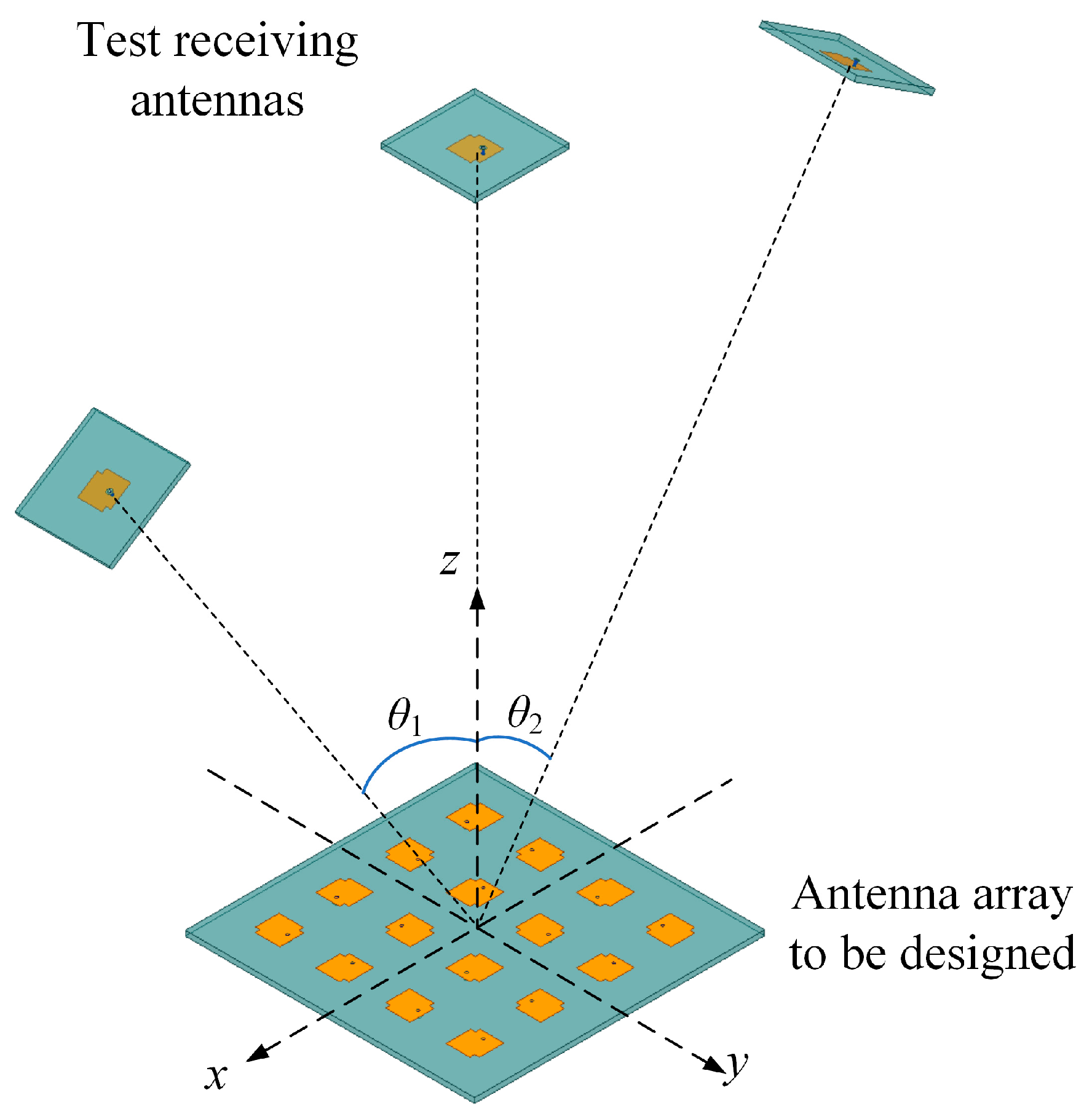
- Set the test receiving antennas at proper positions. In general, the test receiving antennas should evenly cover the area that needs to be shaped. Based on the angular coverage of the area to be shaped, the number of test receiving antennas may vary from case to case, and should be carefully decided. Thus, the shaping area is divided into many small areas. If the number of test receiving antennas is too small, a depression may occur in the curve of gain. Therefore, dividing the target area into two or four parts and placing the receiving antennas at the junctions and edges may be a suitable choice, according to the simulation experiences.
- (3)
- Calculate the scattering parameters. While the arrangement of the antenna array to be designed and test antennas is determined, the multiple-input multiple-output system is formed. A full-wave simulation can be conducted using commercial simulation software, such as HFSS, CST, and FEKO. As a result, the simulated scattering matrix is obtained and used for further optimization.
- (4)
- Obtain the optimal excitations for the antenna array to be designed. Once the scattering matrix is achieved, the optimal amplitudes and phases for the transmitting antenna elements can be obtained using (7). The optimal distribution of excitations can then be accomplished via a feeding network or RF circuits depending on the actual requirements.
3. Optimal Antenna Array Design
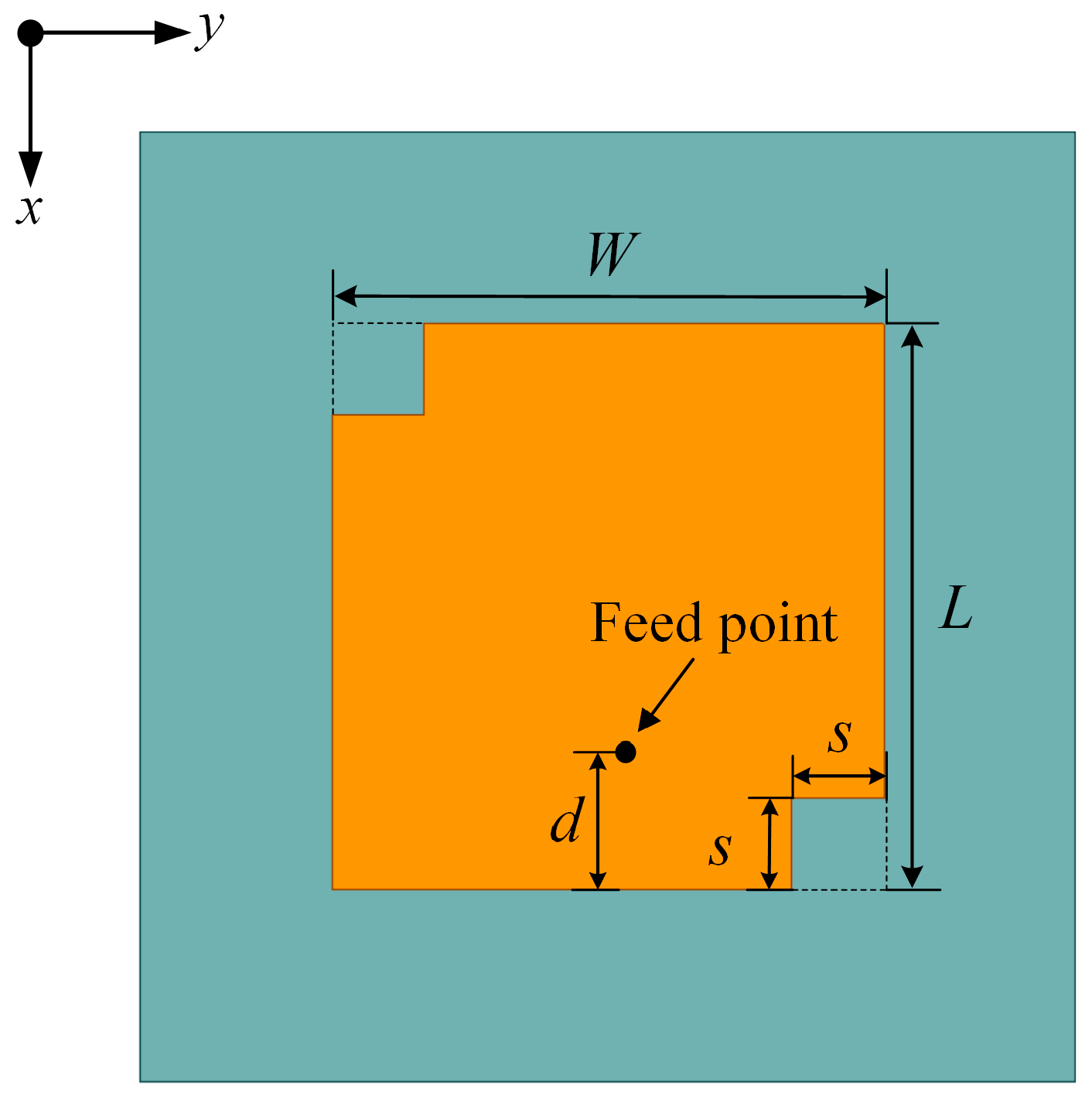
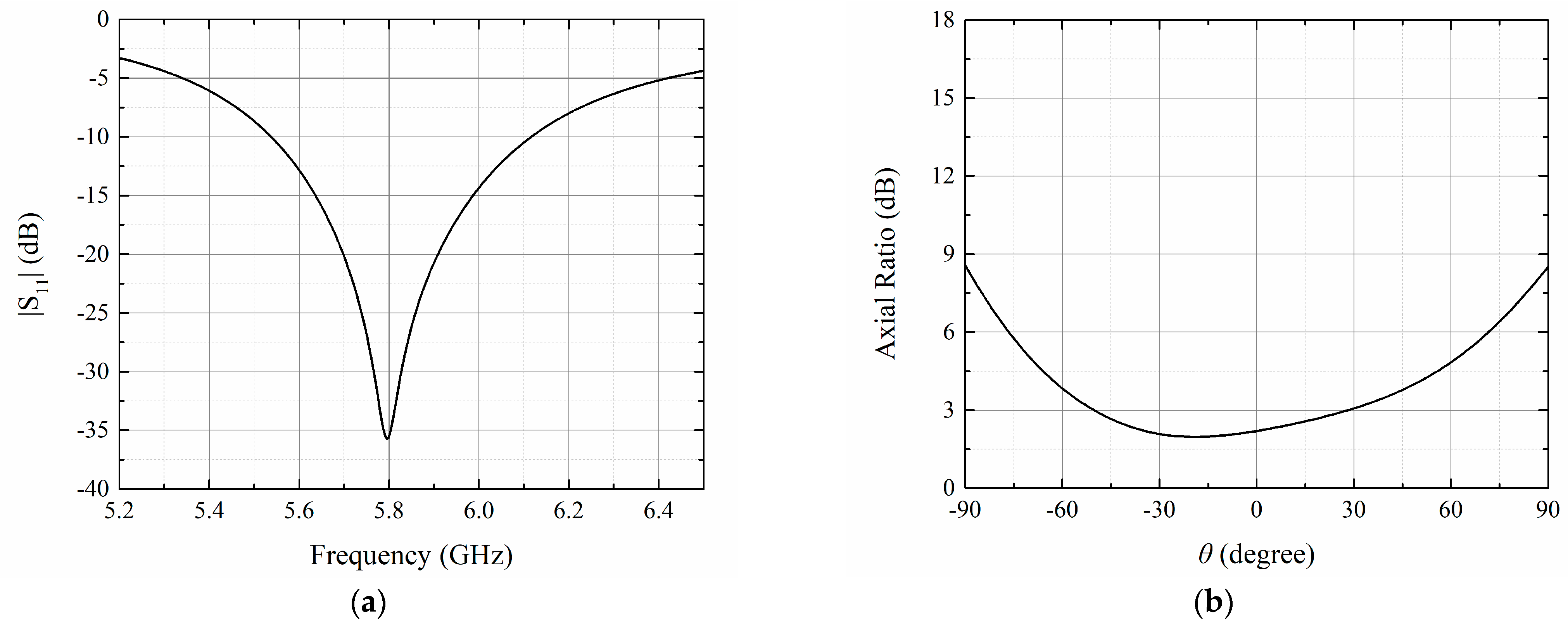
3.1. Antenna Element Design
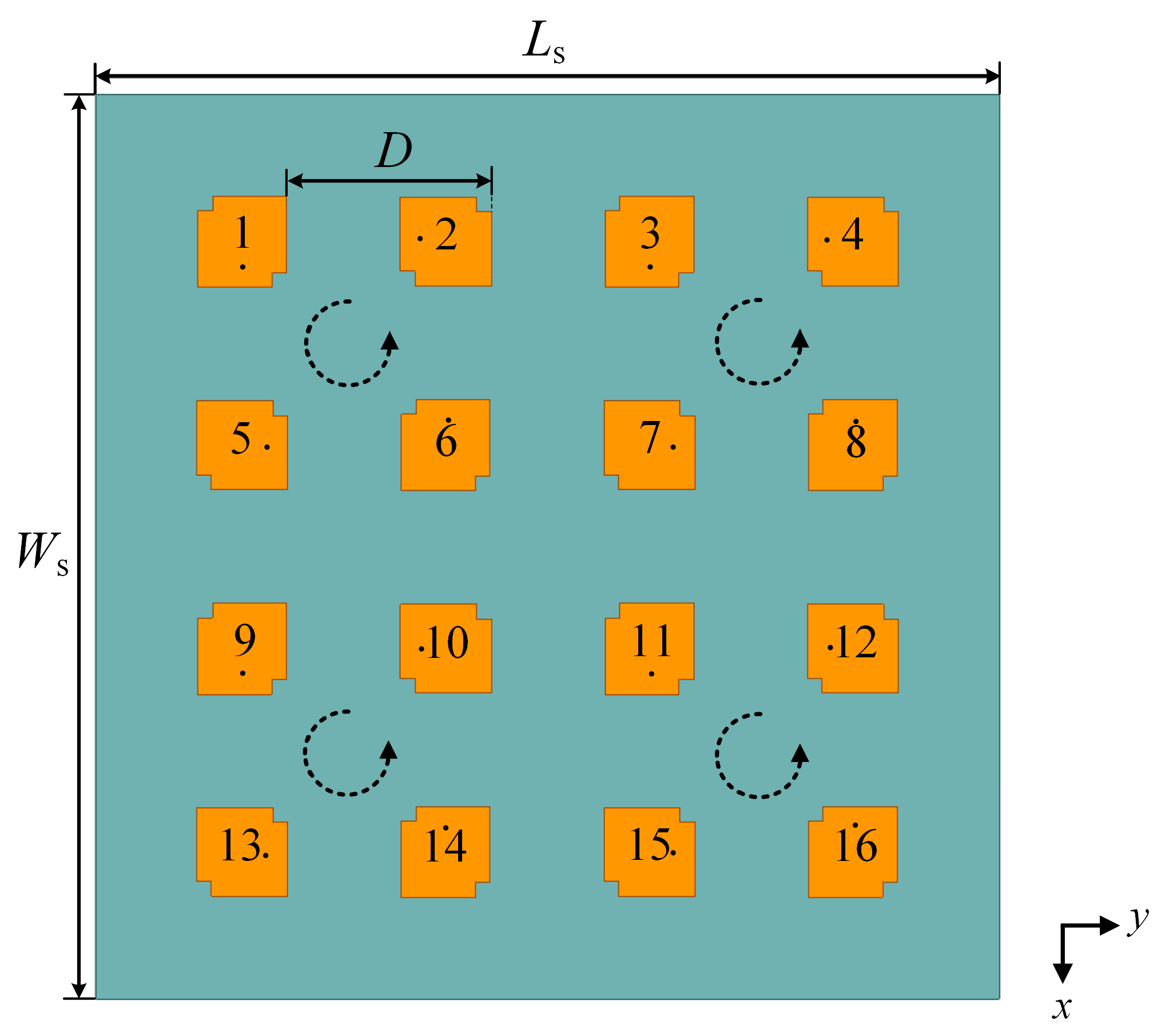
3.2. Antenna Array Design and Excitation Optimization
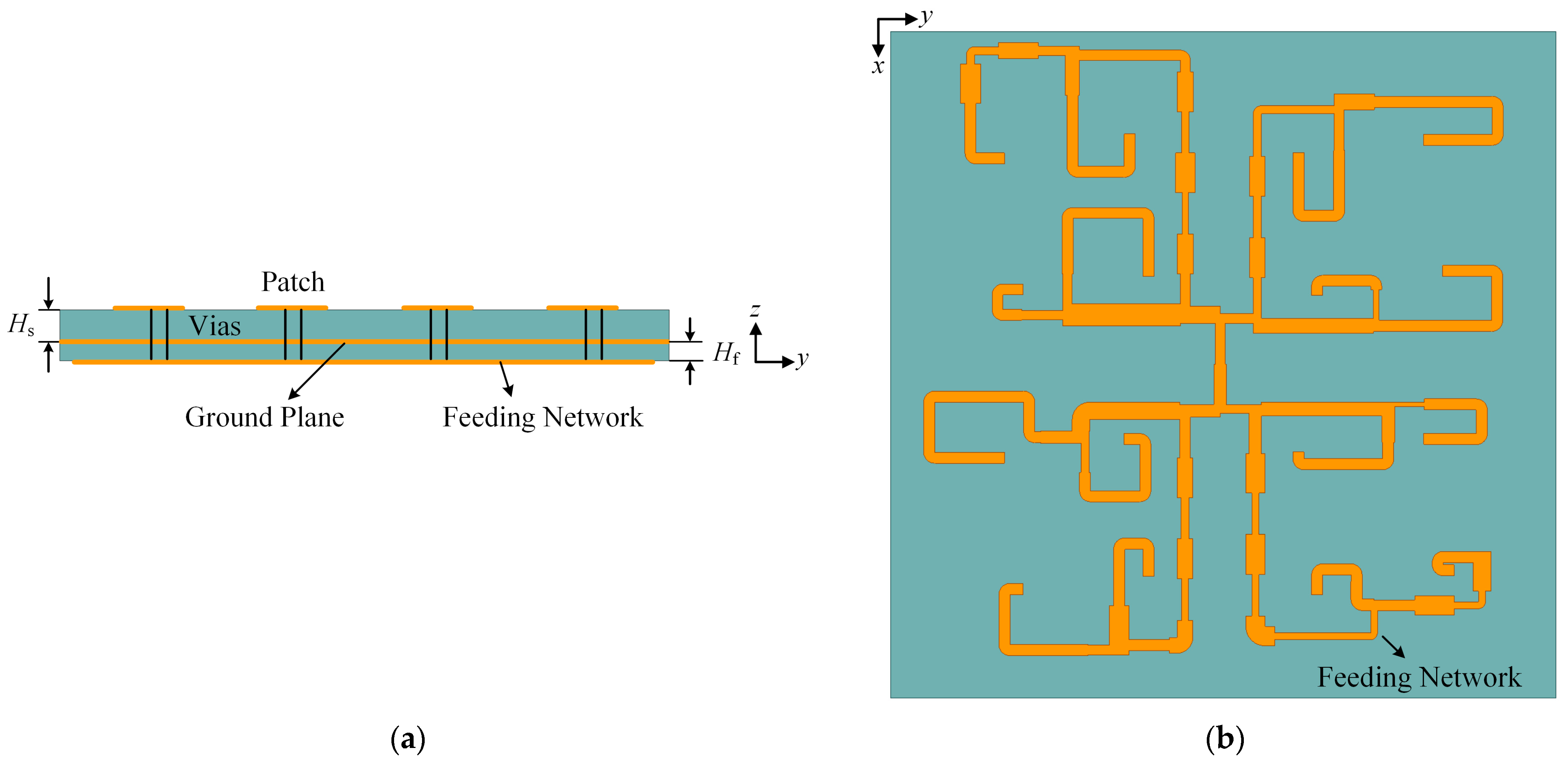
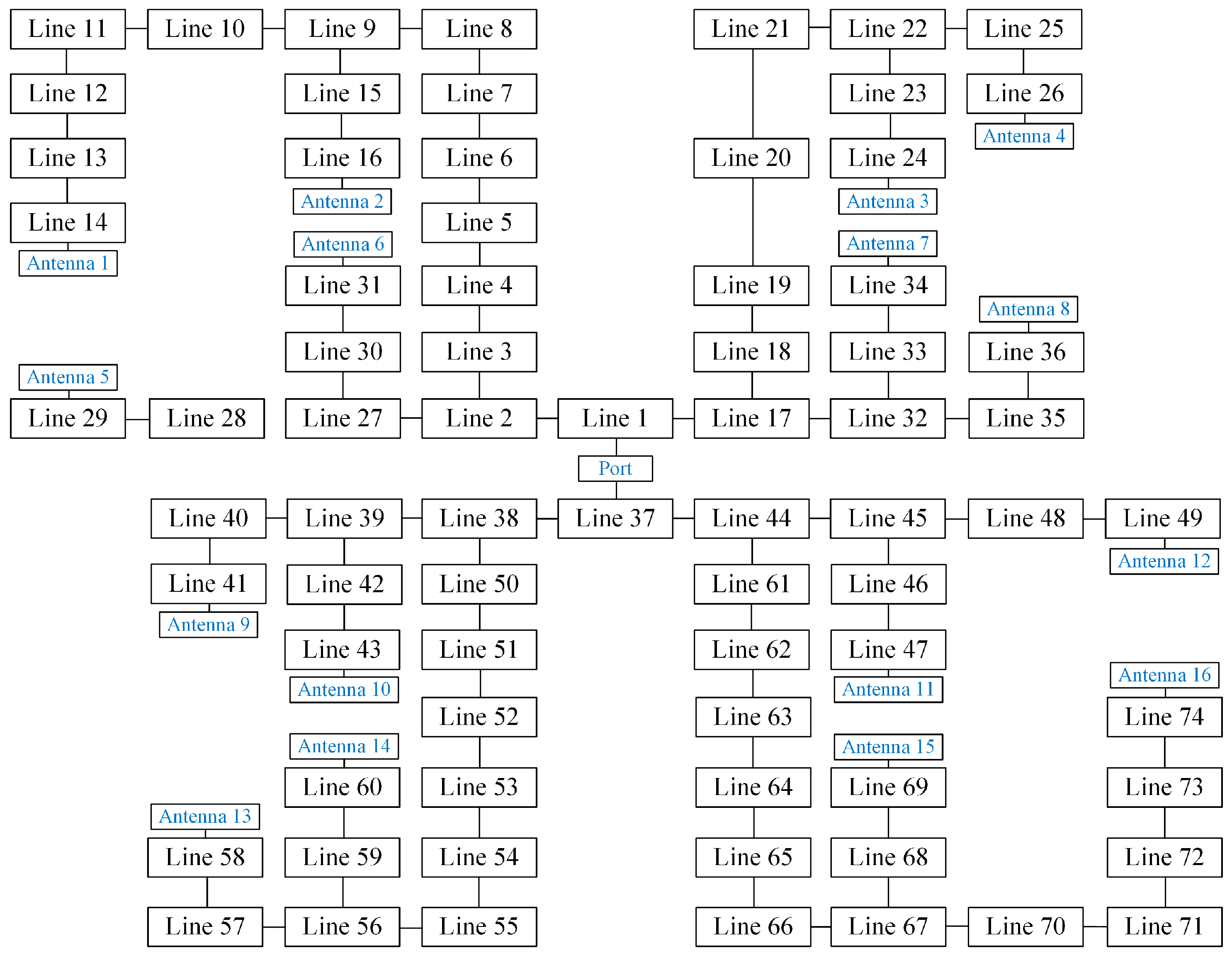
3.3. Feeding Network Design
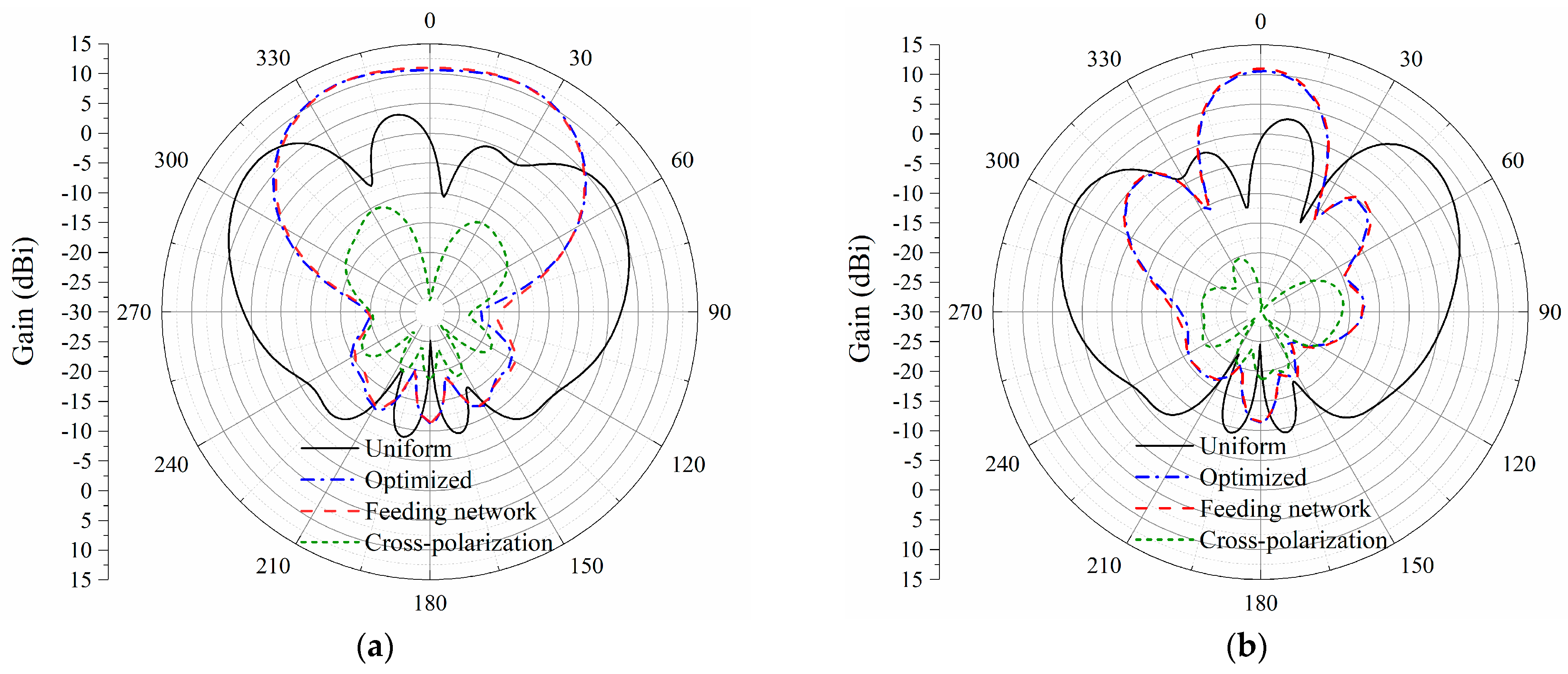
4. Results and Discussion
5. Conclusions
Author Contributions
Funding
Institutional Review Board Statement
Informed Consent Statement
Data Availability Statement
Acknowledgments
Conflicts of Interest
References
- Wang, C.H.; Chen, Y.K.; Yang, S.W. Dual-Band Dual-Polarized Antenna Array with Flat-Top and Sharp Cutoff Radiation Patterns for 2G/3G/LTE Cellular Bands. IEEE Trans. Antennas Propag. 2018, 66, 5907–5917. [Google Scholar] [CrossRef]
- Monavar, F.M.; Shamsinejad, S.; Mirzavand, R.; Melzer, J.; Mousavi, P. Beam-Steering SIW Leaky-Wave Subarray with Flat-Topped Footprint for 5G Applications. IEEE Trans. Antennas Propag. 2017, 65, 1108–1120. [Google Scholar] [CrossRef]
- Xu, M.M.; Zhang, C.; Qiao, H.D.; Zhang, Q.J.; Deng, C.J.; Yu, W.H. Sparse Antenna Array with Flat-Top and Sharp Cutoff Radiation Patterns. IEEE Trans. Antennas Propag. 2023, 71, 4695–4703. [Google Scholar] [CrossRef]
- Cai, X.; Wen, G.Y. An Optimization Method for the Synthesis of Flat-Top Radiation Patterns in the Near- and Far-Field Regions. IEEE Trans. Antennas Propag. 2019, 67, 980–987. [Google Scholar] [CrossRef]
- Yao, Y.; Cui, C.X.; Yu, J.S.; Chen, X.D. A meander line UHF RFID reader antenna for near-field applications. IEEE Trans. Antennas Propag. 2017, 65, 82–91. [Google Scholar] [CrossRef]
- Qing, X.M.; Chen, Z.N. Characteristics of a metal-backed loop antenna and its application to a high-Frequency RFID smart shelf. IEEE Antennas Propag. Mag. 2009, 51, 26–38. [Google Scholar] [CrossRef]
- Dong, Y.; Cai, X.; Wen, G.Y. Circularly Polarized Antenna Array with Suppressed Sidelobes for Electronic Toll Collection. IEEE Antennas Wireless Propag. Lett. 2022, 22, 988–992. [Google Scholar] [CrossRef]
- Inserra, D.; Hu, W.; Wen, G.J. Antenna Array Synthesis for RFID-Based Electronic Toll Collection. IEEE Trans. Antennas Propag. 2018, 66, 4596–4605. [Google Scholar] [CrossRef]
- Zhang, Z.H.; Li, M.; Dai, Q.; Tang, M.C.; Zhu, L. Compact, Wideband, Dual-Band Polarization and Pattern Diversity Antenna for Vehicle Communications. IEEE Trans. Antennas Propag. 2023, 71, 4528–4533. [Google Scholar] [CrossRef]
- Kannappan, L.; Palaniswamy, S.K.; Wang, L.L.; Kanagasabai, M.; Kumar, S.; Alsath, M.G.N.; Rao, T.R. Quad-port multiservice diversity antenna for automotive applications. Sensors 2021, 21, 8238. [Google Scholar] [CrossRef]
- GB/T20851-2007; The National Specifications of P. R. China on ETC/DSRC. Ministry of Transport of the People’s Republic of China: Beijing, China, 2007.
- EN 300 674-1; European Standard for Electromagnetic Compatibility and Radio Spectrum Matters: Road Transport and Traffic Telematics (RTTT); Dedicated Short Range Communication (DSRC) Transmission Equipment (500 kbit/s/250 kbit/s) Operating in the 5.8 GHz Industrial, Scientific and Medical (ISM) Band; Part 1: General Characteristics and Test Methods for Road Side Units (RSU) and on-Board Units (OBU). European Telecommunications Standards Institute (ETSI): Sophia Antipolis, France, 2004; Rev. V1.2.1.
- Nguyen, N.T.; Sauleau, R.; Le, C.L. Reduced-Size Double-Shell Lens Antenna with Flat-Top Radiation Pattern for Indoor Communications at Millimeter Waves. IEEE Trans. Antennas Propag. 2011, 59, 2424–2429. [Google Scholar] [CrossRef]
- Chen, C.; Zhang, B.; Huang, K.M. Nonuniform Fabry–Perot Leaky-Wave Antenna with Flat-Topped Radiation Patterns for Microwave Wireless Power Transmission. IEEE Antennas Wireless Propag. Lett. 2019, 18, 1863–1867. [Google Scholar] [CrossRef]
- Nguyen, D.M.; Au, N.D.; Seo, C. Aperture-Coupled Patch Antenna with Flat-Top Beam for Microwave Power Transmission. IEEE Antennas Wireless Propag. Lett. 2022, 21, 2130–2134. [Google Scholar] [CrossRef]
- Nobuyuki, T.; Katsumi, K.; Mizuki, M.; Naoki, S.; Tomohiko, M. Large-Scale Sequentially-Fed Array Antenna Radiating Flat-Top Beam for Microwave Power Transmission to Drones. IEEE J. Microw. 2022, 2, 297–306. [Google Scholar]
- Rao, S.K.; Tang, M.Q. Stepped-reflector antenna for dual-band multiple beam Satellite communications payloads. IEEE Trans. Antennas Propag. 2006, 54, 801–811. [Google Scholar] [CrossRef]
- Soliman, S.A.M.; Eldesouki, E.M.; Attiya, A.M. Analysis and Design of an X-Band Reflectarray Antenna for Remote Sensing Satellite System. Sensors 2022, 22, 1166. [Google Scholar] [CrossRef]
- Chen, C.; Pourkazemi, A.; Zhao, W.; van den Brande, N.; Hauffman, T.; Zhang, Z.Y.; Stiens, J. A new exploration of quality testing technique for the wafer-scale graphene film based on the terahertz vector network analysis technology. Appl. Surf. Sci. 2023, 616, 156498. [Google Scholar] [CrossRef]
- Chen, C.; Zhao, W.; Zhang, H.Y.; Hauffman, T.; Zhang, Z.Y.; Stiens, J. Improvement of absorbing stability of carbon nanofibers in sub-terahertz domain using the surface modification of zinc oxide. Ceram. Int. 2023, 49, 18491–18501. [Google Scholar] [CrossRef]
- Li, Z.H.; Chen, C.; Zhang, H.Y.; Xie, Y.L.; Zhao, W.; Zhang, Z.Y.; Stiens, J. Design and optimization of a graphene-enhanced tunable wire-grid-like polarizer operating in the 0.5-0.75 THz band. Diam. Relat. Mater. 2023, 138, 110177. [Google Scholar] [CrossRef]
- Kumar, O.P.; Kumar, P.; Ali, T.; Kumar, P.; Subhash, K.K. A Quadruple Notch UWB Antenna with Decagonal Radiator and Sierpinski Square Fractal Slots. J. Sens. Actuator Netw. 2023, 12, 24. [Google Scholar] [CrossRef]
- Woodward, P.M.; Lawson, J.D. The theoretical precision with which an arbitrary radiation-pattern may be obtained from a source of finite size. J. Inst. Elect. Eng. III Radio Commun. Eng. 1948, 95, 363–370. [Google Scholar]
- Thadeu Freitas de Abreu, G.; Kohno, R. A modified Dolph-Chebyshev approach for the synthesis of low sidelobe beampatterns with adjustable beamwidth. IEEE Trans. Antennas Propag. 2003, 51, 3014–3017. [Google Scholar] [CrossRef]
- Zhang, X.S.; Guo, C.J.; Hou, B.H. A Modified Dolph-Chebyshev Approach for Synthesis of Array Antennas. Aeronautical Computing Tech. 2009, 39, 46–48+51. [Google Scholar]
- Chakraborty, A.; Das, B.N.; Sanyal, G.S. Beam shaping using nonlinear phase distribution in a uniformly spaced array. IEEE Trans. Antennas Propag. 1982, 30, 1031–1034. [Google Scholar] [CrossRef]
- Vlaminck, V.; Temdie, L.; Castel, V.; Jungfleisch, M.B.; Stoeffler, D.; Henry, Y.; Bailleul, M. Spin wave diffraction model for perpendicularly magnetized films. J. Appl. Phys. 2023, 133, 53903. [Google Scholar] [CrossRef]
- López-Álvarez, C.; Rodríguez-González, J.A.; López-Martín, M.E.; Ares-Pena, F.J. An Improved Pattern Synthesis Iterative Method in Planar Arrays for Obtaining Efficient Footprints with Arbitrary Boundaries. Sensors 2021, 21, 2358. [Google Scholar]
- Li, J.Y.; Qi, Y.X.; Zhou, S.G. Shaped beam synthesis based on superposition principle and Taylor method. IEEE Trans. Antennas Propag. 2017, 65, 6157–6160. [Google Scholar] [CrossRef]
- Lu, G.M.; Sabirova, F.M.; Morozov, A.V. Simulation and experimental measurement of digital multi-beamforming phased antenna array in the frequency range C. Results Phys. 2019, 13, 102310. [Google Scholar]
- Liu, X.; Schmitt, L.; Sievert, B.; Lipka, J.; Geng, C.; Kolpatzeck, K.; Erni, D.; Rennings, A.; Balzer, J.C.; Hoffmann, M.; et al. Terahertz Beam Steering Using a MEMS-Based Reflectarray Configured by a Genetic Algorithm. IEEE Access 2022, 10, 84458–84472. [Google Scholar] [CrossRef]
- Huang, H.; Tang, X. Wideband Multiple Bessel Beams with Desired Directions and Energy Distribution Proportion Based on Time Reversal and Genetic Algorithm in Microwave. IEEE Trans. Mag. 2023, 59, 1–9. [Google Scholar] [CrossRef]
- Bagheri, A.; Safaei, M.; Araghi, A.; Shahabi, S.M.M.; Wang, F.; Khalily, M.; Tafazolli, R. Mathematical Model and Real-World Demonstration of Multi-Beam and Wide-Beam Reconfigurable Intelligent Surface. IEEE Access 2023, 11, 19613–19621. [Google Scholar] [CrossRef]
- Ding, Z.; Xie, J.; Li, Z. Adaptive Transmit Beamspace Optimization Design based on RD-log-FDA Radar. J. Syst. Eng. Electron. 2022, 33, 91–96. [Google Scholar] [CrossRef]
- Park, J.; Lim, H.J.; Trinh-Van, S.; Park, D.; Jung, Y.K.; Lim, D.; Hwang, K.C. Derivation of a Universally Valid Array Factor of a Conformal Arrays Based on Phase Compensation and Genetic Learning Particle Swarm Optimization. Appl. Sci. 2022, 12, 6501. [Google Scholar] [CrossRef]
- Chen, R.; Tian, Z.; Long, W.X.; Wang, X.; Zhang, W. Hybrid Mechanical and Electronic Beam Steering for Maximizing OAM Channel Capacity. IEEE Trans. Wireless Commun. 2023, 22, 534–549. [Google Scholar] [CrossRef]
- Dai, S.W.; Li, M.H.; Abbasi, Q.H.; Imran, M.A. A Zero Placement Algorithm for Synthesis of Flat Top Beam Pattern with Low Sidelobe Level. IEEE Access 2020, 8, 225935–225944. [Google Scholar] [CrossRef]
- Lin, C.; Qing, A.; Feng, Q. Synthesis of unequally spaced antenna arrays by using differential evolution. IEEE Trans. Antennas Propag. 2010, 58, 2553–2561. [Google Scholar]
- Bing, L. A simplified genetic algorithm in multi-beam combination for mm-Wave communication system. Telecom. Sys. 2021, 78, 15–24. [Google Scholar] [CrossRef]
- Wang, H.; Zhang, Z.J.; Feng, Z.H. A beam-switching antenna array with shaped radiation patterns. IEEE Antennas Wireless Propag. Lett. 2012, 11, 818–821. [Google Scholar] [CrossRef]


| Parameter | Value |
|---|---|
| W (mm) | 11.3 |
| L (mm) | 11.6 |
| s (mm) | 1.88 |
| d (mm) | 2.57 |
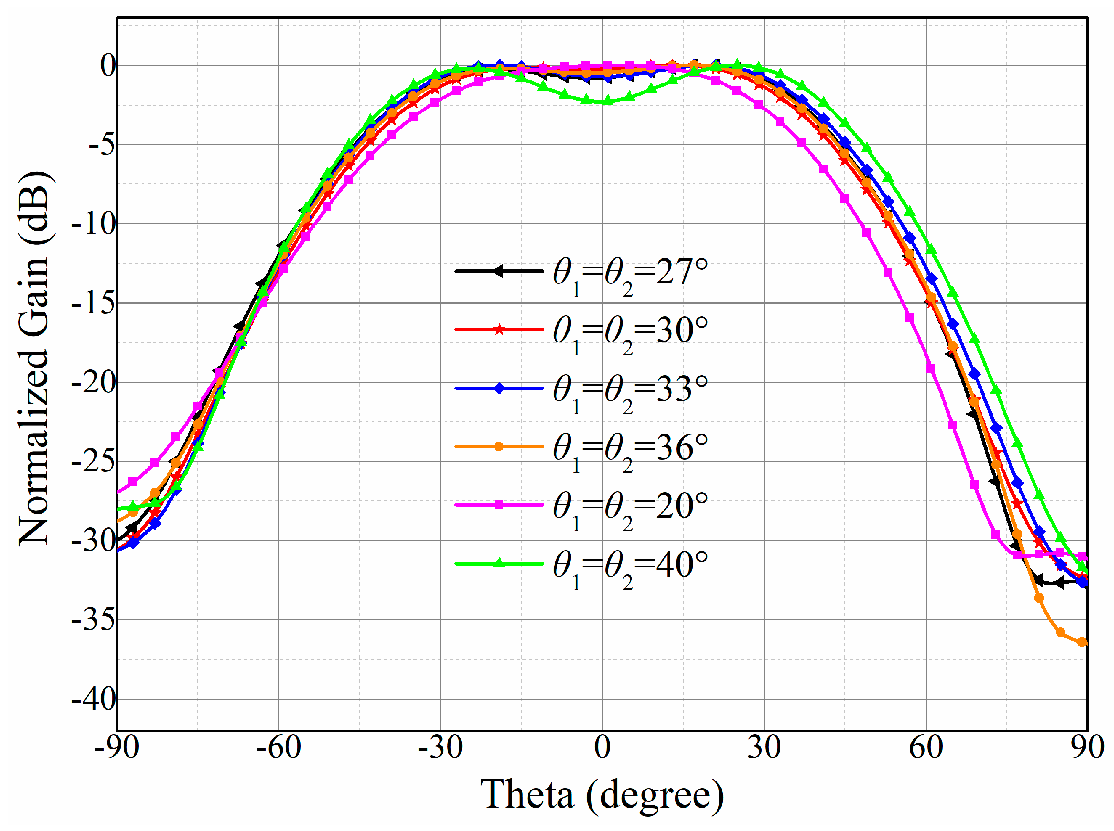
| (Degree) | Gain Fluctuation (dB) |
|---|---|
| 20 | 2.47 |
| 27 | 0.86 |
| 30 | 1.31 |
| 33 | 0.74 |
| 36 | 1.08 |
| 40 | 2.27 |
| Antenna No. | Optimized Excitation |
|---|---|
| 1 | 0.04 V < 51.8° |
| 2 | 0.09 V < 154.1° |
| 3 | 0.06 V < −89.6° |
| 4 | 0.10 V < 147.2° |
| 5 | 0.37 V < 148.2° |
| 6 | 0.28 V < −114.5° |
| 7 | 0.35 V < 139.4° |
| 8 | 0.35 V < −113.0° |
| 9 | 0.33 V < 68.4° |
| 10 | 0.39 V < 31.0° |
| 11 | 0.32 V < 48.9° |
| 12 | 0.37 V < −26.1° |
| 13 | 0.06 V < −32.0° |
| 14 | 0.07 V < 48.4° |
| 15 | 0.07 V < −13.2° |
| 16 | 0.04 V < 85.6° |
| Line No. | Width (mm) | Length (mm) | Line No. | Width (mm) | Length (mm) | Line No. | Width (mm) | Length (mm) |
|---|---|---|---|---|---|---|---|---|
| 1 | 1.75 | 7.04 | 26 | 1.89 | 40.61 | 51 | 2.71 | 6.89 |
| 2 | 2.93 | 6.86 | 27 | 3.77 | 20.30 | 52 | 1.37 | 7.13 |
| 3 | 1.66 | 7.06 | 28 | 1.62 | 7.07 | 53 | 2.71 | 6.89 |
| 4 | 2.71 | 6.89 | 29 | 1.89 | 13.02 | 54 | 1.17 | 7.18 |
| 5 | 1.01 | 7.23 | 30 | 1.62 | 7.07 | 55 | 2.71 | 6.89 |
| 6 | 3.30 | 6.81 | 31 | 1.89 | 35.50 | 56 | 1.89 | 7.02 |
| 7 | 1.37 | 7.13 | 32 | 2.51 | 20.74 | 57 | 1.62 | 7.07 |
| 8 | 2.71 | 6.89 | 33 | 0.92 | 7.25 | 58 | 1.89 | 28.15 |
| 9 | 1.74 | 21.14 | 34 | 1.89 | 14.24 | 59 | 3.36 | 6.81 |
| 10 | 1.57 | 7.08 | 35 | 1.95 | 7.01 | 60 | 1.89 | 21.35 |
| 11 | 2.71 | 6.89 | 36 | 1.89 | 33.29 | 61 | 2.09 | 6.98 |
| 12 | 1.37 | 7.13 | 37 | 2.04 | 6.99 | 62 | 3.30 | 6.81 |
| 13 | 3.52 | 6.79 | 38 | 2.10 | 6.98 | 63 | 1.17 | 7.18 |
| 14 | 1.89 | 15.36 | 39 | 2.99 | 20.50 | 64 | 3.30 | 6.81 |
| 15 | 2.41 | 6.93 | 40 | 2.10 | 6.98 | 65 | 1.17 | 7.18 |
| 16 | 1.89 | 29.72 | 41 | 1.89 | 49.76 | 66 | 3.30 | 6.81 |
| 17 | 1.66 | 7.06 | 42 | 1.39 | 7.12 | 67 | 1.17 | 21.54 |
| 18 | 1.37 | 7.13 | 43 | 1.89 | 28.13 | 68 | 2.00 | 7.00 |
| 19 | 2.71 | 6.89 | 44 | 1.46 | 7.11 | 69 | 1.89 | 13.27 |
| 20 | 1.37 | 7.13 | 45 | 2.39 | 20.80 | 70 | 1.82 | 7.03 |
| 21 | 2.71 | 6.89 | 46 | 2.17 | 6.97 | 71 | 3.30 | 6.81 |
| 22 | 1.37 | 21.38 | 47 | 1.89 | 21.39 | 72 | 1.17 | 7.18 |
| 23 | 1.68 | 7.06 | 48 | 0.80 | 7.29 | 73 | 3.03 | 6.85 |
| 24 | 1.89 | 29.24 | 49 | 1.89 | 25.94 | 74 | 1.89 | 11.22 |
| 25 | 2.76 | 6.88 | 50 | 1.77 | 7.04 |
| Antenna No. | Optimized Excitation |
|---|---|
| 1 | 0.03 V < 51.8° |
| 2 | 0.08 V < 154.1° |
| 3 | 0.05 V < −89.6° |
| 4 | 0.9 V < 147.2° |
| 5 | 0.36 V < 148.2° |
| 6 | 0.27 V < −114.1° |
| 7 | 0.34 V < 139.4° |
| 8 | 0.35 V < −113.0° |
| 9 | 0.34 V < 68.9° |
| 10 | 0.40 V < 32.9° |
| 11 | 0.33 V < 49.0° |
| 12 | 0.39 V < −26.9° |
| 13 | 0.06 V < −32.2° |
| 14 | 0.06 V < 47.4° |
| 15 | 0.06 V < −12.9° |
| 16 | 0.03 V < 86.5° |
| Ref. | Frequency (GHz) | Gain Fluctuation (dB) | Minimum AR (dB) | 3-dB AR Beam Coverage | Sidelobe Level (dB) | Antenna Size |
|---|---|---|---|---|---|---|
| [7] | 5.8 | 12.9 | 0.3 | (−23°, 23°) | <−30 | 120 mm × 125.2 mm × 2 mm (2.22 λ × 2.42 λ × 0.04 λ) |
| [8] | 0.92 | 13 | <2 | Not given | <−22 | 590 mm × 590 mm × 1.524 mm (1.81 λ × 1.81 λ × 0.005 λ) |
| [9] | 3.8 | >1 | 1.8 | (−18°, 40°) | <−8 | 138 mm × 138 mm × 6.15 mm (1.75 λ × 1.75 λ × 0.08 λ) |
| This work | 5.8 | <0.7 | 0.202 | (−54°, 56°) | <−11.4 | 114.7 mm × 115 mm × 3 mm (2.22 λ × 2.22 λ × 0.06 λ) |
Disclaimer/Publisher’s Note: The statements, opinions and data contained in all publications are solely those of the individual author(s) and contributor(s) and not of MDPI and/or the editor(s). MDPI and/or the editor(s) disclaim responsibility for any injury to people or property resulting from any ideas, methods, instructions or products referred to in the content. |
© 2023 by the authors. Licensee MDPI, Basel, Switzerland. This article is an open access article distributed under the terms and conditions of the Creative Commons Attribution (CC BY) license (https://creativecommons.org/licenses/by/4.0/).
Share and Cite
Xu, T.; Xu, M.; Cai, X. The Design of a Circularly Polarized Antenna Array with Flat-Top Beam for an Electronic Toll Collection System. Sensors 2023, 23, 9388. https://doi.org/10.3390/s23239388
Xu T, Xu M, Cai X. The Design of a Circularly Polarized Antenna Array with Flat-Top Beam for an Electronic Toll Collection System. Sensors. 2023; 23(23):9388. https://doi.org/10.3390/s23239388
Chicago/Turabian StyleXu, Tianfan, Mengchi Xu, and Xiao Cai. 2023. "The Design of a Circularly Polarized Antenna Array with Flat-Top Beam for an Electronic Toll Collection System" Sensors 23, no. 23: 9388. https://doi.org/10.3390/s23239388
APA StyleXu, T., Xu, M., & Cai, X. (2023). The Design of a Circularly Polarized Antenna Array with Flat-Top Beam for an Electronic Toll Collection System. Sensors, 23(23), 9388. https://doi.org/10.3390/s23239388