
Longitudinal Spin Seebeck Effect Thermopiles Based on Flexible Co-Rich Amorphous Ribbons/Pt Thin-Film Heterostructures

 ,
, 
 , ,
, ,  ,
, 
Abstract
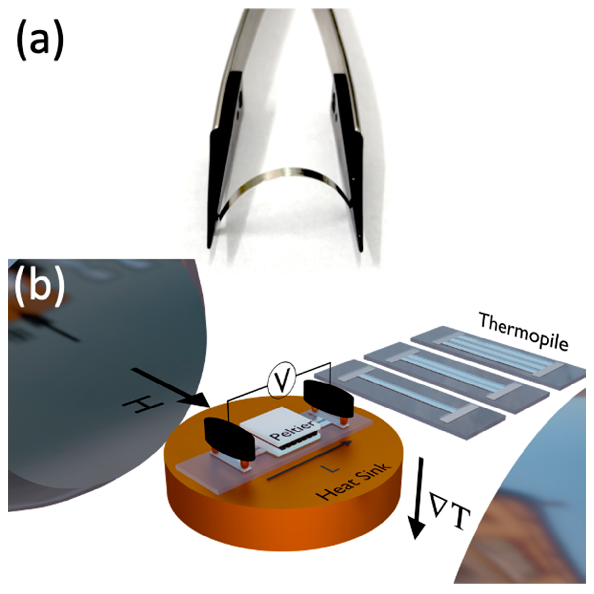
:1. Introduction
2. Materials and Methods
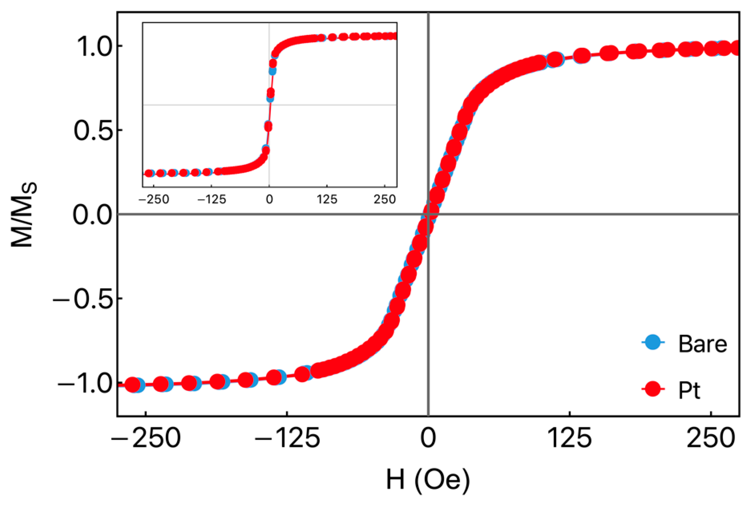
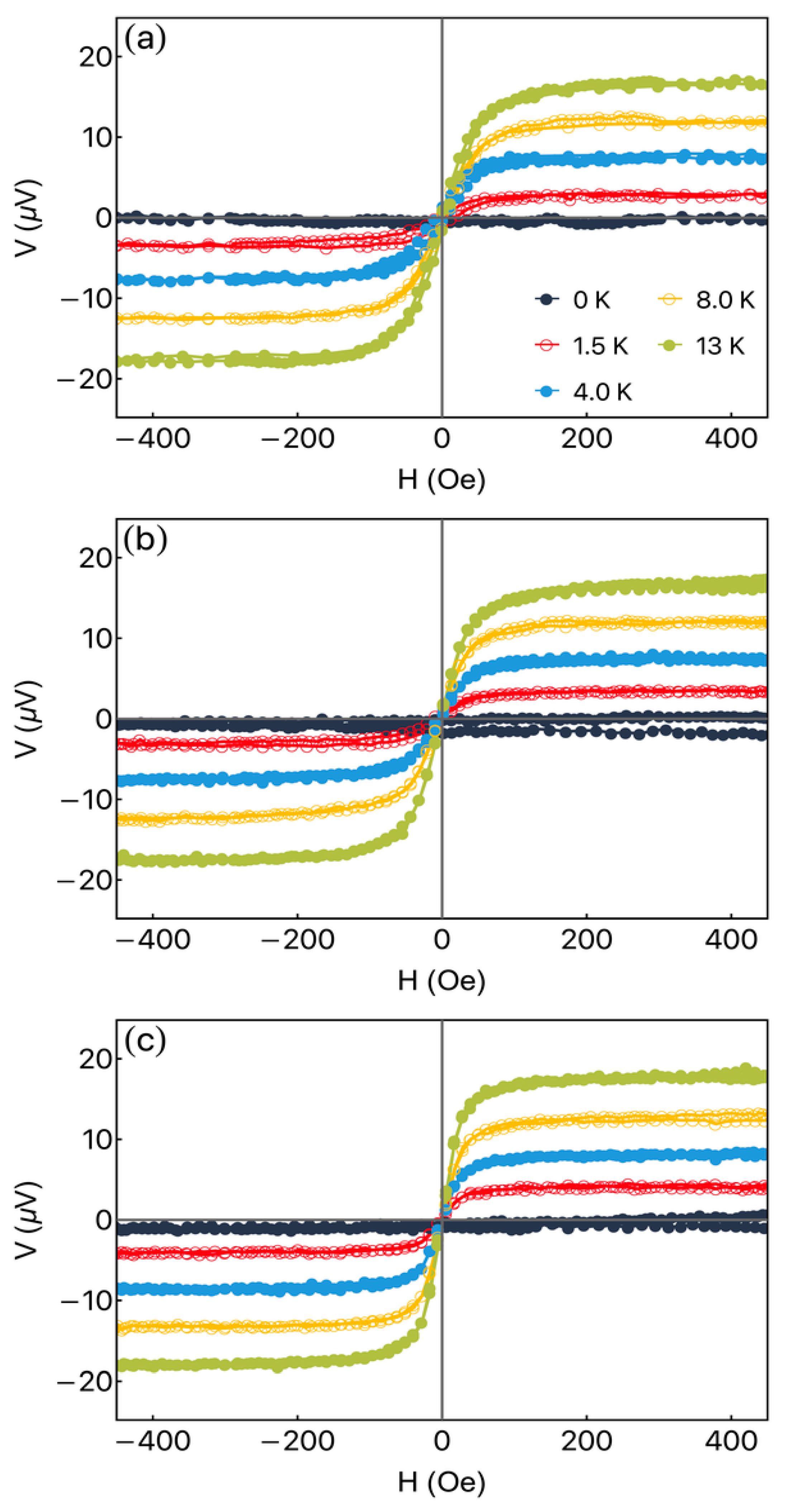
3. Results and Discussion
4. Conclusions
Author Contributions
Funding
Institutional Review Board Statement
Informed Consent Statement
Data Availability Statement
Conflicts of Interest
References
- Nykyruy, Y.; Mudry, S.; Kulyk, Y.; Prunitsa, V.; Borysiuk, A. Magnetic properties and nanocrystallization behavior of Co-based amorphous alloy. Phys. Chem. Solid State 2023, 24, 106–113. [Google Scholar] [CrossRef]
- Murugaiyan, P.; Mitra, A.; Panda, A.K.; Kumar, A.; Roy, R.K.; Manna, K.; Srivastava, S.K. Electromagnetic interference shielding effectiveness of amorphous and nanocomposite soft magnetic ribbons. Phys. B Condens. Matter 2019, 568, 13–17. [Google Scholar] [CrossRef]
- Beach, R.; Berkowitz, A. Sensitive field-and frequency-dependent impedance spectra of amorphous FeCoSiB wire and ribbon. J. Appl. Phys. 1994, 76, 6209–6213. [Google Scholar] [CrossRef]
- Volchkov, S.O.; Pasynkova, A.A.; Derevyanko, M.S.; Bukreev, D.A.; Kozlov, N.V.; Svalov, A.V.; Semirov, A.V. Magnetoimpedance of CoFeCrSiB Ribbon-Based Sensitive Element with FeNi Covering: Experiment and Modeling. Sensors 2021, 21, 6728. [Google Scholar] [CrossRef]
- Makhotkin, V.E.; Shurukhin, B.P.; Lopatin, V.A.; Marchukov, P.Y.; Levin, Y.K. Magnetic field sensors based on amorphous ribbons. Sens. Act. A Phys. 1991, 27, 759–762. [Google Scholar] [CrossRef]
- Gazda, P.; Nowicki, M. Giant Stress-Impedance Effect in CoFeNiMoBSi Alloy in Variation of Applied Magnetic Field. Materials 2021, 14, 1919. [Google Scholar] [CrossRef]
- Semirov, A.V.; Bukreev, D.A.; Moiseev, A.A.; Derevyanko, M.S.; Kudryavtsev, V.O. Relationship Between the Temperature Changes of the Magnetostriction Constant and the Impedance of Amorphous Elastically Deformed Soft Magnetic Cobalt-Based Ribbons. Russ. Phys. J. 2013, 55, 977–982. [Google Scholar] [CrossRef]
- Kurlyandskaya, G.V.; Sánchez, M.L.; Hernando, B.; Prida, V.M.; Gorria, P.; Tejedor, M. Giant-magnetoimpedance-based sensitive element as a model for biosensors. Appl. Phys. Lett. 2003, 82, 3053–3055. [Google Scholar] [CrossRef]
- Yang, Z.; Lei, C.; Zhou, Y.; Cheng Sun, X. Study on the giant magnetoimpedance effect in micro-patterned Co-based amorphous ribbons with single strip structure and tortuous shape. Microsyst. Technol. 2015, 21, 1995–2001. [Google Scholar] [CrossRef]
- Knobel, M.; Vazquez, M.; Kraus, L. Giant magnetoimpedance. In Handbook of Magnetic Materials; Buschow, K.H.J., Ed.; Elsevier: Amsterdam, The Netherlands, 2003; Volume 15, pp. 497–563. [Google Scholar]
- Cox, C.D.W.; Caruana, A.J.; Cropper, M.D.; Morrison, K. Anomalous Nernst effect in Co2MnSi thin films. J. Phys. D Appl. Phys. 2020, 53, 035005. [Google Scholar] [CrossRef]
- Tian, D.; Li, Y.; Qu, D.; Jin, X.; Chien, C.L. Separation of spin Seebeck effect and anomalous Nernst effect in Co/Cu/YIG. App. Phys. Lett. 2015, 106, 212407. [Google Scholar] [CrossRef]
- Uchida, K.; Xiao, J.; Adachi, H.; Ohe, J.; Takahashi, S.; Ieda, J.; Ota, T.; Kajiwara, Y.; Umezawa, H.; Kawai, H.; et al. Spin Seebeck insulator. Nat. Mater. 2010, 9, 894–897. [Google Scholar] [CrossRef]
- Chen, T.; Minami, S.; Sakai, A.; Wang, Y.; Feng, Z.; Nomoto, T.; Hirayama, M.; Ishii, R.; Koretsune, T.; Arita, R.; et al. Large anomalous Nernst effect and nodal plane in an iron-based kagome ferromagnet. Sci. Adv. 2022, 8, eabk1480. [Google Scholar] [CrossRef] [PubMed]
- Melo, A.S.; de Oliveira, A.B.; Chesman, C.; Pace, R.D.D.; Bohn, F.; Correa, M.A. Anomalous Nernst effect in stressed magnetostrictive film grown onto flexible substrate. Sci. Rep. 2019, 9, 15338. [Google Scholar] [CrossRef] [PubMed]
- Asaba, T.; Ivanov, V.; Thomas, S.M.; Savrasov, S.Y.; Thompson, J.D.; Bauer, E.D.; Ronning, F. Colossal anomalous Nernst effect in a correlated noncentrosymmetric kagome ferromagnet. Sci. Adv. 2021, 7, eabf1467. [Google Scholar] [CrossRef]
- Xing, Y.; Feng Sun, Q.; Wang, J. Nernst and Seebeck effects in a graphene nanoribbon. Phys. Rev. B 2009, 80, 235411. [Google Scholar] [CrossRef]
- Correa, M.A.; Ferreira, A.; Souza, A.L.R.; Neto, J.M.D.; Bohn, F.; Vaz, F.; Kurlyandskaya, G.V. Anomalous Nernst Effect in Flexible Co-Based Amorphous Ribbons. Sensors 2023, 23, 1420. [Google Scholar] [CrossRef]
- Geishendorf, K.; Vir, P.; Shekhar, C.; Felser, C.; Facio, J.I.; van den Brink, J.; Nielsch, K.; Thomas, A.; Goennenwein, S.T.B. Signatures of the Magnetic Entropy in the Thermopower Signals in Nanoribbons of the Magnetic Weyl Semimetal Co3Sn2S2. Nano Lett. J. 2020, 20, 300–305. [Google Scholar] [CrossRef]
- Kai, W.; Lin, P.; Chen, W.; Kao, P.; Huang, R.; Liaw, P. Air-oxidation of a Co-based amorphous ribbon at 400–600 °C. J. Alloys Compd. 2011, 509, S179–S183. [Google Scholar] [CrossRef]
- Park, D.; Kim, C.; Kim, W.; Hong, J. Study of GMI-valve characteristics in the Co-based amorphous ribbon by ferromagnetic resonance. J. Magn. Magn. Mater. 2007, 310, 2295–2297. [Google Scholar] [CrossRef]
- Egbu, J.; Ohodnicki, P.R., Jr.; Baltrus, J.P.; Talaat, A.; Wright, R.F.; McHenry, M.E. Analysis of surface roughness and oxidation of FeNi-based metal amorphous nanocomposite alloys. J. Alloys Compd. 2022, 912, 165155. [Google Scholar] [CrossRef]
- Clark, A.; Zhu, A.; Sun, K.; Petty, H.R. Cerium oxide and platinum nanoparticles protect cells from oxidant-mediated apoptosis. J. Nanoparticle Res. 2011, 13, 5547–5555. [Google Scholar] [CrossRef]
- Xu, M.; Chen, F.; Wang, T.; Yu, B.; Zhao, Z.; Zhou, L.; Hua, D. Platinum Nanoparticles Anchored on Covalent Triazine Frameworks Modified Cordierite for Efficient Oxidation of Hydrogen Isotopes. ACS Appl. Nano Mater. 2023, 6, 867–874. [Google Scholar] [CrossRef]
- Pragnell, W.; Evans, H.; Williams, A. Oxidation protection of Sm2Co17-based alloys. J. Alloys Compd. 2012, 517, 92–97. [Google Scholar] [CrossRef]
- Castel, V.; Vlietstra, N.; Youssef, J.B.; van Wees, B.J. Platinum thickness dependence of the inverse spin-Hall voltage from spin pumping in a hybrid yttrium iron garnet/platinum system. Appl. Phys. Lett. 2012, 101, 132414. [Google Scholar] [CrossRef]
- Sun, Y.; Chang, H.; Kabatek, M.; Song, Y.Y.; Wang, Z.; Jantz, M.; Schneider, W.; Wu, M.; Montoya, E.; Kardasz, B.; et al. Damping in Yttrium Iron Garnet Nanoscale Films Capped by Platinum. Phys. Rev. Lett. 2013, 111, 106601. [Google Scholar] [CrossRef]
- Adachi, H.; Ichi Uchida, K.; Saitoh, E.; Maekawa, S. Theory of the spin Seebeck effect. Rep. Prog. Phys. 2013, 76, 036501. [Google Scholar] [CrossRef]
- Snyder, G.J.; Toberer, E.S. Complex thermoelectric materials. Nat. Mater. 2008, 7, 105–114. [Google Scholar] [CrossRef] [PubMed]
- Uchida, K.; Takahashi, S.; Harii, K.; Ieda, J.; Koshibae, W.; Ando, K.; Maekawa, S.; Saitoh, E. Observation of the spin Seebeck effect. Nature 2008, 455, 778–781. [Google Scholar] [CrossRef]
- Holanda, J.; Santos, O.A.; Cunha, R.O.; Mendes, J.B.; Rodríguez-Suárez, R.L.; Azevedo, A.; Rezende, S.M. Longitudinal spin Seebeck effect in permalloy separated from the anomalous Nernst effect: Theory and experiment. Phys. Rev. B 2017, 95, 214421. [Google Scholar] [CrossRef]
- Uchida, K.; Nonaka, T.; Yoshino, T.; Kikkawa, T.; Kikuchi, D.; Saitoh, E. Enchancement of Spin-Seebeck Voltage by Spin-Hall Thermopile. Appl. Phys. Exp. 2012, 5, 093001. [Google Scholar] [CrossRef]
- Kim, J.M.; Jeon, C.Y.; Kim, D.J.; Van, P.C.; Jeong, J.R.; Park, B.G. Amplification of Spin Thermoelectric Signal in Multilayer Spin Thermopiles. ACS Appl. Electron. Mater. 2020, 2, 2906–2912. [Google Scholar] [CrossRef]
- Kim, D.J.; Lee, K.D.; Surabhi, S.; Yoon, S.G.; Jeong, J.R.; Park, B.G. Utilization of Antiferromagnetic IrMn electrode in Spin thermoelectric devices and their beneficial hybrid for thermopiles. Adv. Func. Mater. 2016, 26, 5507. [Google Scholar] [CrossRef]
- Weng, T.W.; Chuang, T.C.; Qu, D.; Huang, S.Y. Anomalous Nernst thermopile made of single element iron. J. Magn. Magn. Mater. 2022, 563, 169892. [Google Scholar] [CrossRef]
- Fal Miyar, V.; Cerdeira, M.A.; García, J.A.; Potatov, A.P.; Pierna, A.R.; Marzo, F.F.; Barandiarán, J.M.; Kurlyandskaya, G.V. Giant magnetoimpedance of electrochemically surface modified Co-based amorphous ribbons. IEEE Trans. Magn. 2008, 44, 4476–4479. [Google Scholar] [CrossRef]
- Kurlyandskaya, G.V.; Lezama, L.; Pasynkova, A.A.; Volchkov, S.O.; Lukshina, V.A.; Larrañaga, A.; Dmitrieva, N.V.; Timofeeva, A.V.; Orue, I. Amorphous FeCoCrSiB Ribbons with Tailored Anisotropy for the Development of Magnetic Elements for High Frequency Applications. Materials 2022, 15, 4160. [Google Scholar] [CrossRef] [PubMed]
- Kurlyandskaya, G.; Dmitrieva, N.; Zayarnaya, T.; Lukshina, V.; Potapov, A. The thermomechanical treatment of an amorphous Co-based alloy with a low Curie temperature. J. Magn. Magn. Mater. 1996, 160, 307–308. [Google Scholar] [CrossRef]
- Althammer, M.; Meyer, S.; Nakayama, H.; Schreier, M.; Altmannshofer, S.; Weiler, M.; Huebl, H.; Geprãgs, S.; Opel, M.; Gross, R.; et al. Quantitative study of the spin Hall magnetoresistance in ferromagnetic insulator/normal metal hybrids. Phys. Rev. B 2013, 87, 224401. [Google Scholar] [CrossRef]
- Melzer, M.; Kaltenbrunner, M.; Makarov, D.; Karnaushenko, D.; Karnaushenko, D.; Sekitani, T.; Someya, T.; Schmidt, O.G. Imperceptible magnetoelectronics. Nat. Commun. 2015, 6, 6080. [Google Scholar] [CrossRef]


Disclaimer/Publisher’s Note: The statements, opinions and data contained in all publications are solely those of the individual author(s) and contributor(s) and not of MDPI and/or the editor(s). MDPI and/or the editor(s) disclaim responsibility for any injury to people or property resulting from any ideas, methods, instructions or products referred to in the content. |
© 2023 by the authors. Licensee MDPI, Basel, Switzerland. This article is an open access article distributed under the terms and conditions of the Creative Commons Attribution (CC BY) license (https://creativecommons.org/licenses/by/4.0/).
Share and Cite
Correa, M.A.; Svalov, A.V.; Ferreira, A.; Gamino, M.; Silva, E.F.d.; Bohn, F.; Vaz, F.; de Oliveira, D.F.; Kurlyandskaya, G.V. Longitudinal Spin Seebeck Effect Thermopiles Based on Flexible Co-Rich Amorphous Ribbons/Pt Thin-Film Heterostructures. Sensors 2023, 23, 7781. https://doi.org/10.3390/s23187781
Correa MA, Svalov AV, Ferreira A, Gamino M, Silva EFd, Bohn F, Vaz F, de Oliveira DF, Kurlyandskaya GV. Longitudinal Spin Seebeck Effect Thermopiles Based on Flexible Co-Rich Amorphous Ribbons/Pt Thin-Film Heterostructures. Sensors. 2023; 23(18):7781. https://doi.org/10.3390/s23187781
Chicago/Turabian StyleCorrea, Marcio A., Andrey V. Svalov, Armando Ferreira, Matheus Gamino, Edimilson F. da Silva, Felipe Bohn, Filipe Vaz, Danniel F. de Oliveira, and Galina V. Kurlyandskaya. 2023. "Longitudinal Spin Seebeck Effect Thermopiles Based on Flexible Co-Rich Amorphous Ribbons/Pt Thin-Film Heterostructures" Sensors 23, no. 18: 7781. https://doi.org/10.3390/s23187781
APA StyleCorrea, M. A., Svalov, A. V., Ferreira, A., Gamino, M., Silva, E. F. d., Bohn, F., Vaz, F., de Oliveira, D. F., & Kurlyandskaya, G. V. (2023). Longitudinal Spin Seebeck Effect Thermopiles Based on Flexible Co-Rich Amorphous Ribbons/Pt Thin-Film Heterostructures. Sensors, 23(18), 7781. https://doi.org/10.3390/s23187781