
Review on Type of Sensors and Detection Method of Anti-Collision System of Unmanned Aerial Vehicle


 ,
,  ,
, 
 and
and 
Abstract
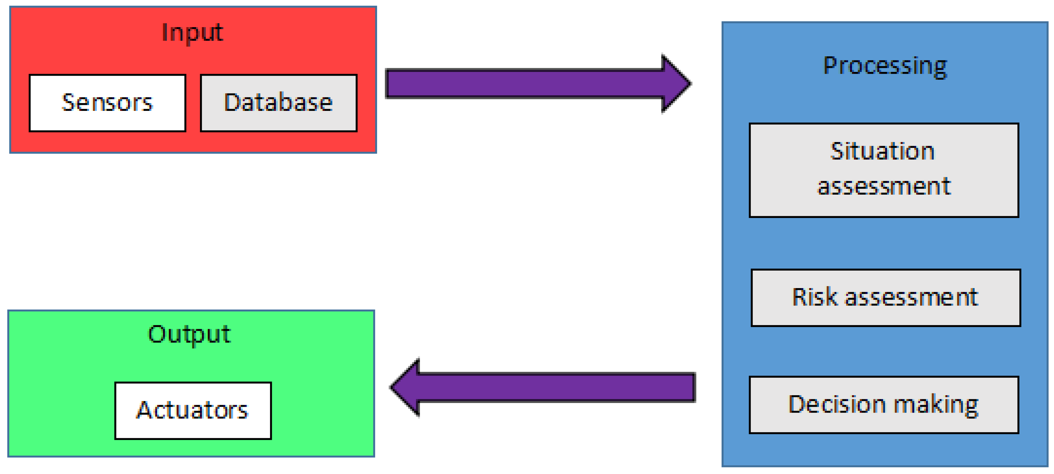
1. Introduction
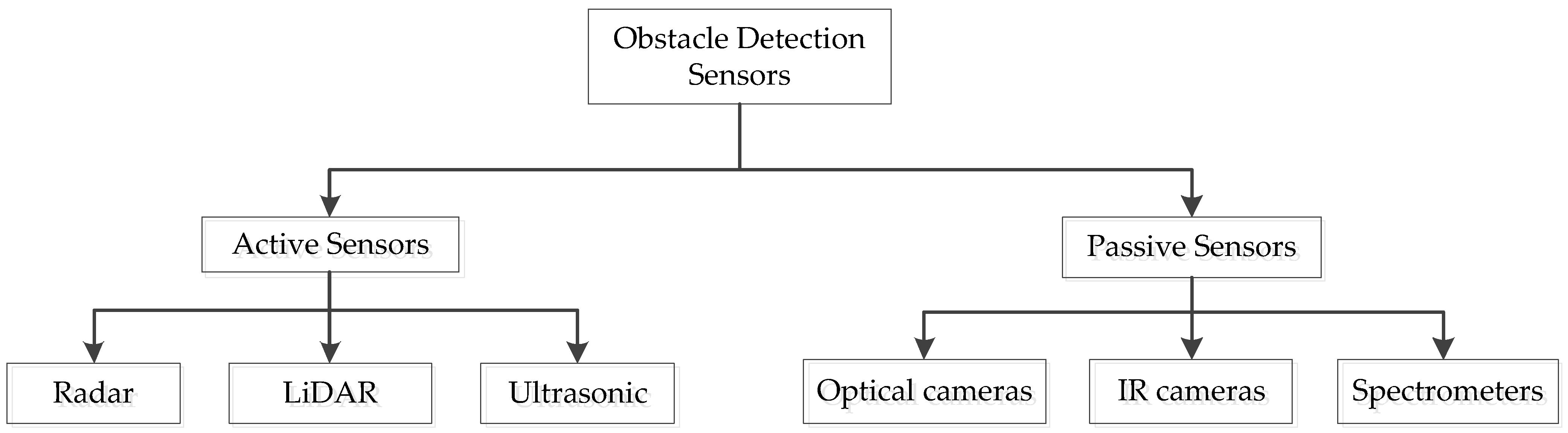
2. Obstacle Detection Sensors
2.1. Active Sensors
2.1.1. Radar
2.1.2. LiDAR
2.1.3. Ultrasonic
2.2. Passive Sensors
2.2.1. Optical
2.2.2. Infrared
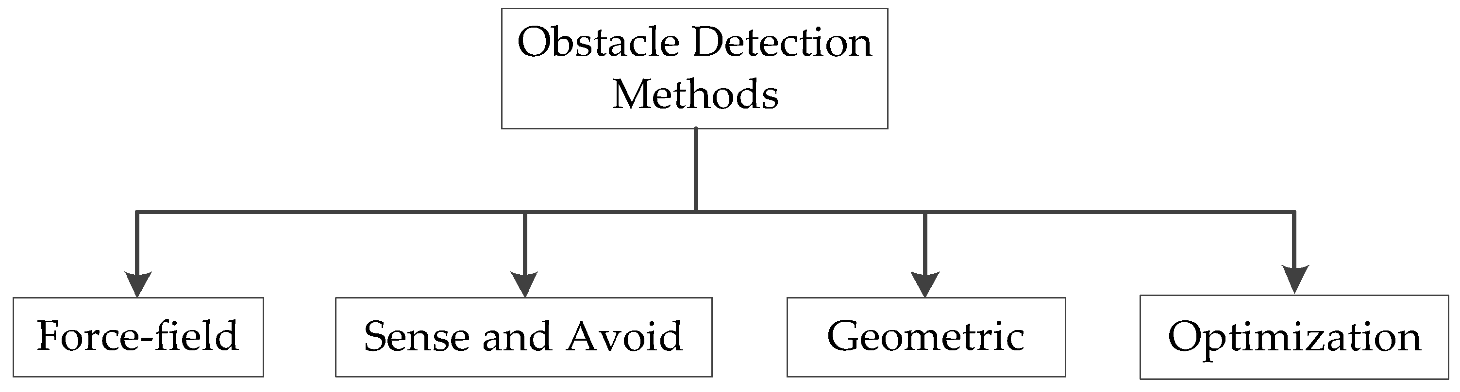
3. Obstacle Detection Method
3.1. Force-Field Method
3.2. Sense and Avoid Method
3.3. Geometric Method
3.4. Optimization Method
3.5. Summary of Object Detection Method
4. Conclusions
Author Contributions
Funding
Institutional Review Board Statement
Informed Consent Statement
Data Availability Statement
Acknowledgments
Conflicts of Interest
References
- Zosimovych, N. Preliminary design of a VTOL unmanned aerial system for remote sensing of landscapes. Aeron Aero Open Access J. 2020, 4, 62–67. [Google Scholar] [CrossRef]
- Papa, U.; Ponte, S. Preliminary Design of an Unmanned Aircraft System for Aircraft General Visual Inspection. Electronics 2018, 7, 435. [Google Scholar] [CrossRef]
- Giernacki, W.; Gośliński, J.; Goślińska, J.; Espinoza-Fraire, T.; Rao, J. Mathematical Modeling of the Coaxial Quadrotor Dynamics for Its Attitude and Altitude Control. Energies 2021, 14, 1232. [Google Scholar] [CrossRef]
- Gheorghiţă, D.; Vîntu, I.; Mirea, L.; Brăescu, C. Quadcopter control system. In Proceedings of the 2015 19th International Conference on System Theory, Control and Computing (ICSTCC), Cheile Gradistei, Romania, 14–16 October 2015; pp. 421–426. [Google Scholar]
- Huang, H.-M. Autonomy levels for unmanned systems (ALFUS) framework: Safety and application issues. In Proceedings of the 2007 Workshop on Performance Metrics for Intelligent Systems, Washington, DC, USA, 28–30 August 2007. [Google Scholar]
- Zhang, W.; Zelinsky, G.; Samaras, D. Real-time accurate object detection using multiple resolutions. In Proceedings of the 2007 IEEE 11th International Conference on Computer Vision, Rio De Janeiro, Brazil, 14–21 October 2007. [Google Scholar]
- Holovatyy, A.; Teslyuk, V.; Lobur, M. VHDL-AMS model of delta-sigma modulator for A/D converter in MEMS interface circuit. Perspective Technologies and Methods In MEMS Design. In Proceedings of the MEMSTECH 2015—11th International Conference, Lviv, Ukraine, 2–6 September 2015; pp. 55–57. [Google Scholar] [CrossRef]
- Holovatyy, A.; Lobur, M.; Teslyuk, V. VHDL-AMS model of mechanical elements of MEMS tuning fork gyroscope for the schematic level of computer-aided design. Perspective Technologies and Methods. In Proceedings of the 2008 International Conference on Perspective Technologies and Methods in MEMS Design, Lviv, Ukraine, 21–24 May 2008; pp. 138–140. [Google Scholar] [CrossRef]
- Zhuge, C.; Cai, Y.; Tang, Z. A novel dynamic obstacle avoidance algorithm based on collision time histogram. Chin. J. Electron. 2017, 6, 522–529. [Google Scholar] [CrossRef]
- Puchalski, R.; Giernacki, W. UAV Fault Detection Methods, State-of-the-Art. Drones 2022, 6, 330. [Google Scholar] [CrossRef]
- Bondyra, A.; Kołodziejczak, M.; Kulikowski, R.; Giernacki, W. An Acoustic Fault Detection and Isolation System for Multirotor UAV. Energies 2022, 15, 3955. [Google Scholar] [CrossRef]
- Chao, H.; Cao, Y.; Chen, Y. Autopilots for small fixed-wing unmanned air vehicles: A survey. In Proceedings of the 2007 International Conference on Mechatronics and Automation, Harbin, China, 5–8 August 2007. [Google Scholar]
- Vijayavargiya, A.; Sharma, A.; Anirudh; Kumar, A.; Kumar, A.; Yadav, A.; Sharma, A.; Jangid, A.; Dubey, A. Unmanned aerial vehicle. Imp. J. Interdiscip. 2016, 2, 1747–1750. [Google Scholar]
- Shim, D.; Chung, H.; Kim, H.J.; Sastry, S. Autonomous exploration in unknown urban environments for unmanned aerial vehicles. In Proceedings of the AIAA Guidance, Navigation, and Control Conference and Exhibit, San Francisco, CA, USA, 15–18 August 2005. [Google Scholar]
- Mikołajczyk, T.; Mikołajewski, D.; Kłodowski, A.; Łukaszewicz, A.; Mikołajewska, E.; Paczkowski, T.; Macko, M.; Skornia, M. Energy Sources of Mobile Robot Power Systems: A Systematic Review and Comparison of Efficiency. Appl. Sci. 2023, 13, 7547. [Google Scholar] [CrossRef]
- Zhang, A.; Zhou, D.; Yang, M.; Yang, P. Finite-time formation control for unmanned aerial vehicle swarm system with time-delay and input saturation. IEEE Access Pract. Innov. Open Solut. 2019, 7, 5853–5864. [Google Scholar] [CrossRef]
- Yasin, J.N.; Mohamed, S.A.S.; Haghbayan, M.-H.; Heikkonen, J.; Tenhunen, H.; Plosila, J. Unmanned aerial vehicles (UAVs): Collision avoidance systems and approaches. IIEEE Access Pract. Innov. Open Solut. 2020, 8, 105139–105155. [Google Scholar] [CrossRef]
- Mircheski, I.; Łukaszewicz, A.; Szczebiot, R. Injection process design for manufacturing of bicycle plastic bottle holder using CAx tools. Procedia Manuf. 2019, 32, 68–73. [Google Scholar] [CrossRef]
- Kiefer, R.J.; Grimm, D.K.; Litkouhi, B.B.; Sadekar, V. Collision Avoidance System. U.S. Patent 7 245 231 2007, 6 August 2004. [Google Scholar]
- Foka, A.; Trahanias, P. Real-time hierarchical POMDPs for autonomous robot navigation. Robot. Auton. Syst. 2020, 55, 561–571. [Google Scholar] [CrossRef]
- Murray, R.M. Recent research in cooperative control of multivehicle systems. J. Dyn. Syst. Meas. Control 2007, 129, 571–598. [Google Scholar] [CrossRef]
- Ladd, G.; Bland, G. Non-military applications for small UAS platforms. In Proceedings of the AIAA Infotech@Aerospace Conference, Washington, DC, USA, 6–9 April 2009. [Google Scholar]
- He, L.; Bai, P.; Liang, X.; Zhang, J.; Wang, W. Feedback formation control of UAV swarm with multiple implicit leaders. Aerosp. Sci. Technol. 2018, 72, 327–334. [Google Scholar] [CrossRef]
- Esfahlani, S.S. Mixed reality and remote sensing application of unmanned aerial vehicle in fire and smoke detection. J. Ind. Inf. Integr. 2019, 15, 42–49. [Google Scholar] [CrossRef]
- Valavanis, K.P. Unmanned Aircraft Systems: The Current State-of-the Art; Springer: Cham, Switzerland, 2016. [Google Scholar]
- Wargo, C.A.; Church, G.C.; Glaneueski, J.; Strout, M. Unmanned Aircraft Systems (UAS) research and future analysis. In Proceedings of the 2014 IEEE Aerospace Conference, Big Sky, MT, USA, 1–8 March 2014. [Google Scholar]
- Horla, D.; Giernacki, W.; Báča, T.; Spurny, V.; Saska, M. AL-TUNE: A Family of Methods to Effectively Tune UAV Controllers in In-flight Conditions. J. Intell. Robot Syst. 2021, 103, 5. [Google Scholar] [CrossRef]
- Wang, X.; Yadav, V.; Balakrishnan, S.N. Cooperative UAV formation flying with obstacle/collision avoidance. IEEE Trans. Control. Syst. Technol. A Publ. IEEE Control. Syst. Soc. 2007, 15, 672–679. [Google Scholar] [CrossRef]
- Łukaszewicz, A.; Panas, K.; Szczebiot, R. Design process of technological line to vegetables packaging using CAx tools. In Proceedings of the 17th International Scientific Conference on Engineering for Rural Development, Jelgava, Latvia, 23–25 May 2018; pp. 871–887. [Google Scholar] [CrossRef]
- Łukaszewicz, A.; Szafran, K.; Jóźwik, J. CAx techniques used in UAV design process. In Proceedings of the 2020 IEEE 7th International Workshop on Metrology for AeroSpace (MetroAeroSpace), Pisa, Italy, 22–24 June 2020; pp. 95–98. [Google Scholar] [CrossRef]
- Active Sensors. (n.d.). Esa.int. Available online: https://www.esa.int/Education/7.ActiveSensors (accessed on 15 December 2022).
- What Is Active Sensor?—Definition. Available online: https://internetofthingsagenda.techtarget.com/defisensor (accessed on 13 March 2020).
- Blanc, C.; Aufrère, R.; Malaterre, L.; Gallice, J.; Alizon, J. Obstacle detection and tracking by millimeter wave RADAR. IFAC Proc. Vol. 2004, 37, 322–327. [Google Scholar] [CrossRef]
- Korn, B.; Edinger, C. UAS in civil airspace: Demonstrating “sense and avoid” capabilities in flight trials. In Proceedings of the 2008 IEEE/AIAA 27th Digital Avionics Systems Conference, St. Paul, MN, USA, 26–30 October 2008. [Google Scholar]
- Owen, M.P.; Duffy, S.M.; Edwards, M.W.M. Unmanned aircraft sense and avoid radar: Surrogate flight testing performance evaluation. In Proceedings of the 2014 IEEE Radar Conference, Cincinnati, OH, USA 19–23 May 2014. [Google Scholar]
- Quist, E.B.; Beard, R.W. Radar odometry on fixed-wing small unmanned aircraft. IEEE Trans. Aerosp. Electron. Syst. 2016, 52, 396–410. [Google Scholar] [CrossRef]
- Kwag, Y.K.; Chung, C.H. UAV based collision avoidance radar sensor. In Proceedings of the 2007 IEEE International Geoscience and Remote Sensing Symposium, Barcelona, Spain, 23–28 July 2007. [Google Scholar]
- Hugler, P.; Roos, F.; Schartel, M.; Geiger, M.; Waldschmidt, C. Radar taking off: New capabilities for UAVs. IEEE Microw. Mag. 2018, 19, 43–53. [Google Scholar] [CrossRef]
- Nijsure, Y.A.; Kaddoum, G.; Khaddaj Mallat, N.; Gagnon, G.; Gagnon, F. Cognitive chaotic UWB-MIMO detect-avoid radar for autonomous UAV navigation. IEEE Trans. Intell. Transp. Syst. A Publ. IEEE Intell. Transp. Syst. Counc. 2016, 17, 3121–3131. [Google Scholar] [CrossRef]
- Mohamed, S.A.S.; Haghbayan, M.-H.; Westerlund, T.; Heikkonen, J.; Tenhunen, H.; Plosila, J. A survey on odometry for autonomous navigation systems. IEEE Access Pract. Innov. Open Solut. 2019, 7, 97466–97486. [Google Scholar] [CrossRef]
- Nashashibi, F.; Bargeton, A. Laser-based vehicles tracking and classification using occlusion reasoning and confidence estimation. In Proceedings of the 2008 IEEE Intelligent Vehicles Symposium, Eindhoven, The Netherlands, 4–6 June 2008. [Google Scholar]
- Nüchter, A.; Lingemann, K.; Hertzberg, J.; Surmann, H. 6D SLAM-3D mapping outdoor environments: 6D SLAM-3D Mapping Outdoor Environments. J. Field Robot. 2007, 24, 699–722. [Google Scholar] [CrossRef]
- Zhang, J.; Singh, S. Visual-lidar odometry and mapping: Low-drift, robust, and fast. In Proceedings of the 2015 IEEE International Conference on Robotics and Automation (ICRA), Seattle, WA, USA, 26–30 May 2015. [Google Scholar]
- Tahir, A.; Böling, J.; Haghbayan, M.-H.; Toivonen, H.T.; Plosila, J. Swarms of unmanned aerial vehicles—A survey. J. Ind. Inf. Integr. 2019, 16, 100106. [Google Scholar] [CrossRef]
- Armingol, J.M.; Alfonso, J.; Aliane, N.; Clavijo, M.; Campos-Cordobés, S.; de la Escalera, A.; del Ser, J.; Fernández, J.; García, F.; Jiménez, F.; et al. Environmental Perception for Intelligent Vehicles; Jiménez, F., Ed.; Butterworth-Heinemann: Oxford, UK, 2018; Volume 2, pp. 23–101. [Google Scholar]
- Wang, C.-C.R.; Lien, J.-J.J. Automatic vehicle detection using local features—A statistical approach. IEEE Trans. Intell. Transp. Syst. A Publ. IEEE Intell. Transp. Syst. Counc. 2008, 9, 83–96. [Google Scholar] [CrossRef]
- Mizumachi, M.; Kaminuma, A.; Ono, N.; Ando, S. Robust sensing of approaching vehicles relying on acoustic cues. Sensors 2014, 14, 9546–9561. [Google Scholar] [CrossRef]
- Kim, J.; Hong, S.; Baek, J.; Kim, E.; Lee, H. Autonomous vehicle detection system using visible and infrared camera. In Proceedings of the 2012 12th International Conference on Control, Automation and Systems, Jeju, Republic of Korea, 17–21 October 2012; pp. 630–634. [Google Scholar]
- Kota, F.; Zsedrovits, T.; Nagy, Z. Sense-and-avoid system development on an FPGA. In Proceedings of the 2019 International Conference on Unmanned Aircraft Systems (ICUAS), Atlanta, Gam, USA, 11–14 June 2019. [Google Scholar]
- Mcfadyen, A.; Durand-Petiteville, A.; Mejias, L. Decision strategies for automated visual collision avoidance. In Proceedings of the 2014 International Conference on Unmanned Aircraft Systems (ICUAS), Orlando, FL, USA, 27–30 May 2014. [Google Scholar]
- Saha, S.; Natraj, A.; Waharte, S. A real-time monocular vision-based frontal obstacle detection and avoidance for low cost UAVs in GPS denied environment. In Proceedings of the 2014 IEEE International Conference on Aerospace Electronics and Remote Sensing Technology, Yogyakarta, Indonesia, 13–14 November 2014. [Google Scholar]
- Mejias, L.; McNamara, S.; Lai, J.; Ford, J. Vision-based detection and tracking of aerial targets for UAV collision avoidance. In Proceedings of the 2010 IEEE/RSJ International Conference on Intelligent Robots and Systems, Taipei, Taiwan, 8–22 October 2010. [Google Scholar]
- Mohamed, S.A.S.; Haghbayan, M.-H.; Heikkonen, J.; Tenhunen, H.; Plosila, J. Towards real-time edge detection for event cameras based on lifetime and dynamic slicing. In Advances in Intelligent Systems and Computing; Springer International Publishing: Berlin/Heidelberg, Germany, 2020. [Google Scholar]
- Lee, T.-J.; Yi, D.-H.; Cho, D.-I.D. A monocular vision sensor-based obstacle detection algorithm for autonomous robots. Sensors 2016, 16, 311. [Google Scholar] [CrossRef]
- Haque, A.U.; Nejadpak, A. Obstacle avoidance using stereo camera. arXiv 2017, arXiv:1705.04114. [Google Scholar]
- Hartmann, W.; Tilch, S.; Eisenbeiss, H.; Schindler, K. Determination of the uav position by automatic processing of thermal images. In Proceedings of the ISPRS—International Archives of the Photogrammetry Remote Sensing and Spatial Information Sciences, Melbourne, Australia, 25 August–1 September 2012; pp. 111–116. [Google Scholar]
- Gupta, A.; Padhi, R.; Indian Inst of Science Bangalore Dept of Aerospace Engineering. Reactive Collision Avoidance of Using Nonlinear Geometric and Differential Geometric Guidance. J. Guid. Control Dyn. 2010, 34, 303–310. [Google Scholar]
- Khatib, O. Real-time obstacle avoidance for manipulators and mobile robots. In Proceedings of the 1985 IEEE International Conference on Robotics and Automation, St. Louis, MS, USA, 25–28 March 2005. [Google Scholar]
- Oroko, J.; Nyakoe, G. Obstacle avoidance and path planning schemes for autonomous navigation of a mobile robot: A review. In Proceedings of the Sustainable Research and Innovation Conference, Delft, The Netherlands, 9 May 2014; pp. 314–318. [Google Scholar]
- Choi, D.; Lee, K.; Kim, D. Enhanced Potential Field Based Collision Avoidance for Unmanned Aerial Vehicles in a Dynamic Environment. In Proceedings of the AIAA Scitech 2020 Forum, Orlando, FL, USA, 6–10 January 2020. [Google Scholar]
- Grodzki, W.; Łukaszewicz, A. Design and manufacture of unmanned aerial vehicles (UAV) wing structure using composite materials. Mater. Werkst. 2015, 46, 269–278. [Google Scholar] [CrossRef]
- Sun, J.; Tang, J.; Lao, S. Collision avoidance for cooperative UAVs with optimized artificial potential field algorithm. Sens. IEEE Access Pract. Innov. Open Solut. 2017, 5, 18382–18390. [Google Scholar] [CrossRef]
- Wolf, M.T.; Burdick, J.W. Artificial potential functions for highway driving with collision avoidance. In Proceedings of the 2008 IEEE International Conference on Robotics and Automation, Pasadena, CA, USA, 19–23 May 2008. [Google Scholar]
- Kim, C.Y.; Kim, Y.H.; Ra, W.-S. Modified 1D virtual force field approach to moving obstacle avoidance for autonomous ground vehicles. J. Electr. Eng. Technol. 2019, 14, 1367–1374. [Google Scholar] [CrossRef]
- Yasin, J.N.; Mohamed, S.A.S.; Haghbayan, M.-H.; Heikkonen, J.; Tenhunen, H.; Plosila, J.M. Navigation of autonomous swarm of drones using translational coordinates. In Advances in Practical Applications of Agents, Multi-Agent Systems, and Trustworthiness; Springer International Publishing: Berlin/Heidelberg, Germany, 2020; pp. 353–362. [Google Scholar]
- Yu, X.; Zhang, Y. Sense and avoid technologies with applications to unmanned aircraft systems: Review and prospects. Prog. Aerosp. Sci. 2015, 74, 152–166. [Google Scholar] [CrossRef]
- Wang, M.; Voos, H.; Su, D. Robust online obstacle detection and tracking for collision-free navigation of multirotor UAVs in complex environments. In Proceedings of the 2018 15th International Conference on Control, Automation, Robotics and Vision (ICARCV), Singapore, 18–21 November 2018. [Google Scholar]
- Sharma, S.U.; Shah, D.J. A practical animal detection and collision avoidance system using computer vision technique. IEEE Access Pract. Innov. Open Solut. 2017, 5, 347–358. [Google Scholar] [CrossRef]
- De Simone, M.; Rivera, Z.; Guida, D. Obstacle avoidance system for unmanned ground vehicles by using ultrasonic sensors. Machine 2018, 6, 18, Version June 19, 2023 submitted to Journal Not Specified 12 of 12. [Google Scholar] [CrossRef]
- Yu, Y.; Tingting, W.; Long, C.; Weiwei, Z. Stereo vision based obstacle avoidance strategy for quadcopter UAV. In Proceedings of the 2018 Chinese Control and Decision Conference (CCDC), Shenyang, China, 9–11 June 2018. [Google Scholar]
- Bilimoria, K. A geometric optimization approach to aircraft conflict resolution. In Proceedings of the 18th Applied Aerodynamics Conference, Denver, CO, USA, 14–17 August 2000. [Google Scholar]
- Goss, J.; Rajvanshi, R.; Subbarao, K. Aircraft conflict detection and resolution using mixed geometric and collision cone approaches. In Proceedings of the AIAA Guidance, Navigation, and Control Conference and Exhibit, San Francisco, CA, USA, 16–19 August 2004. [Google Scholar]
- Seo, J.; Kim, Y.; Kim, S.; Tsourdos, A. Collision avoidance strategies for unmanned aerial vehicles in formation flight. IEEE Trans. Aerosp. Electron. Syst. 2017, 53, 2718–2734. [Google Scholar] [CrossRef]
- Lin, Z.; Castano, L.; Mortimer, E.; Xu, H. Fast 3D collision avoidance algorithm for fixed wing UAS. J. Intell. Robot. Syst. 2020, 97, 577–604. [Google Scholar] [CrossRef]
- Ha, L.N.N.T.; Bui, D.H.P.; Hong, S.K. Nonlinear control for autonomous trajectory tracking while considering collision avoidance of UAVs based on geometric relations. Energies 2019, 12, 1551. [Google Scholar] [CrossRef]
- Pérez-Carabaza, S.; Scherer, J.; Rinner, B.; López-Orozco, J.A.; Besada-Portas, E. UAV trajectory optimization for Minimum Time Search with communication constraints and collision avoidance. Appl. Artif. Intell. 2019, 85, 357–371. [Google Scholar] [CrossRef]
- Boivin, E.; Desbiens, A.; Gagnon, E. UAV collision avoidance using cooperative predictive control. In Proceedings of the 2008 16th Mediterranean Conference on Control and Automation, Ajaccio, France, 25–27 June 2008. [Google Scholar]
- Biswas, S.; Anavatti, S.G.; Garratt, M.A. A particle swarm optimization based path planning method for autonomous systems in unknown terrain. In Proceedings of the 2019 IEEE International Conference on Industry 4.0, Artificial Intelligence, and Communications Technology (IAICT), Bali, Indonesia, 1–3 July 2019. [Google Scholar]
- van den Berg, J.; Wilkie, D.; Guy, S.J.; Niethammer, M.; Manocha, D. LQG-obstacles: Feedback control with collision avoidance for mobile robots with motion and sensing uncertainty. In Proceedings of the 2012 IEEE International Conference on Robotics and Automation, St. Paul, MN, USA, 14–18 May 2012. [Google Scholar]
- Zhu, H.; Alonso-Mora, J. Chance-constrained collision avoidance for MAVs in dynamic environments. IEEE Robot. Autom. Lett. 2019, 4, 776–783. [Google Scholar] [CrossRef]
- Balestrieri, E.; Daponte, P.; De Vito, L.; Picariello, F.; Tudosa, I. Sensors and Measurements for UAV Safety: An Overview. Sensors 2021, 21, 8253. [Google Scholar] [CrossRef] [PubMed]
- Pallottino, F.; Antonucci, F.; Costa, C.; Bisaglia, C.; Figorilli, S.; Menesatti, P. Optoelectronic proximal sensing vehicle-mounted technologies in precision agriculture: A review. Comput. Electron. Agric. 2019, 62, 859–873. [Google Scholar] [CrossRef]
- Hu, W.; Li, X.; Hu, J.; Song, X.; Dong, X.; Kong, D.; Xu, Q.; Ren, C. A rear anti-collision decision-making methodology based on deep reinforcement learning for autonomous commercial vehicles. IEEE Sens. J. 2022, 22, 16370–16380. [Google Scholar] [CrossRef]
- Chen, Y.; Cheng, C.; Zhang, Y.; Li, X.; Sun, L. A Neural Network-Based Navigation Approach for Autonomous Mobile Robot Systems. Appl. Sci. 2022, 12, 7796. [Google Scholar] [CrossRef]


| Sensor | Sensor Size | Power Required | Accuracy | Range | Weather Condition | Light Sensitivity | Cost |
|---|---|---|---|---|---|---|---|
| Radar | Large | High | High | Long | Not Affected | No | High |
| LiDar | Small | Low | Medium | Medium | Affected | No | Medium |
| Ultrasonic | Small | Low | Low | Short | Slightly Affected | No | Low |
| Geometric | Sense and Avoid | Force Field | Optimization | |||||
|---|---|---|---|---|---|---|---|---|
| [78,79] | [80] | [83] | [72] | [74] | [69] | [65] | [82] | |
| Multiple UAV Compatibility | / | / | / | / | / | / | O | / |
| 3D Compatibility | / | / | / | / | / | O | O | / |
| Communication | O | / | / | / | / | O | O | / |
| Alternate Route Generation | / | / | / | / | O | / | / | / |
| Real-time Detection | / | / | / | / | / | / | / | / |
Disclaimer/Publisher’s Note: The statements, opinions and data contained in all publications are solely those of the individual author(s) and contributor(s) and not of MDPI and/or the editor(s). MDPI and/or the editor(s) disclaim responsibility for any injury to people or property resulting from any ideas, methods, instructions or products referred to in the content. |
© 2023 by the authors. Licensee MDPI, Basel, Switzerland. This article is an open access article distributed under the terms and conditions of the Creative Commons Attribution (CC BY) license (https://creativecommons.org/licenses/by/4.0/).
Share and Cite
Chandran, N.K.; Sultan, M.T.H.; Łukaszewicz, A.; Shahar, F.S.; Holovatyy, A.; Giernacki, W. Review on Type of Sensors and Detection Method of Anti-Collision System of Unmanned Aerial Vehicle. Sensors 2023, 23, 6810. https://doi.org/10.3390/s23156810
Chandran NK, Sultan MTH, Łukaszewicz A, Shahar FS, Holovatyy A, Giernacki W. Review on Type of Sensors and Detection Method of Anti-Collision System of Unmanned Aerial Vehicle. Sensors. 2023; 23(15):6810. https://doi.org/10.3390/s23156810
Chicago/Turabian StyleChandran, Navaneetha Krishna, Mohammed Thariq Hameed Sultan, Andrzej Łukaszewicz, Farah Syazwani Shahar, Andriy Holovatyy, and Wojciech Giernacki. 2023. "Review on Type of Sensors and Detection Method of Anti-Collision System of Unmanned Aerial Vehicle" Sensors 23, no. 15: 6810. https://doi.org/10.3390/s23156810
APA StyleChandran, N. K., Sultan, M. T. H., Łukaszewicz, A., Shahar, F. S., Holovatyy, A., & Giernacki, W. (2023). Review on Type of Sensors and Detection Method of Anti-Collision System of Unmanned Aerial Vehicle. Sensors, 23(15), 6810. https://doi.org/10.3390/s23156810