Abstract
In digital communication systems featuring high-resolution analog-to-digital converters (ADCs), the utilization of successive interference cancellation and detection can enhance the capacity of a Gaussian multiple access channel (MAC) by combining signals from multiple transmitters in a non-orthogonal manner. Conversely, in systems employing one-bit ADCs, it is exceedingly difficult to eliminate non-orthogonal interference using digital signal processing due to the considerable distortion present in the received signal when employing such ADCs. As a result, the Gaussian MAC does not yield significant capacity gains in such cases. To address this issue, we demonstrate that, under a given deterministic interference, the capacity of a one-bit-quantized channel becomes equivalent to the capacity without interference when an appropriate threshold value is chosen. This finding suggests the potential for indirect interference cancellation in the analog domain, facilitating the proposition of an efficient successive interference cancellation and detection scheme. We analyze the achievable rate of the proposed scheme by deriving the mutual information between the transmitted and received signals at each detection stage. The obtained results indicate that the sum rate of the proposed scheme generally outperforms conventional methods, with the achievable upper bound being twice as high as that of the conventional methods. Additionally, we have developed an optimal transmit power allocation algorithm to maximize the sum rate in fading channels.
1. Introduction
In modern wireless communication systems, digital signal processing (DSP) is essential to ensure high speed and reliable communication [1,2]. In practice, an inevitable quantization error occurs in analog-to-digital converters (ADCs), which may cause a mismatch between theory and implementation, because most digital communication theories were derived assuming the use of infinite-resolution ADCs. As a result, traditional communication standards, such as long-term evolution, recommended using high-resolution ADCs in receivers.
To satisfy the consistently increasing demand for data rates, recent standards for wireless communication are focusing on utilizing large amounts of unused bandwidth in the millimeter-wave (mmWave) and terahertz frequency bands [3,4,5,6,7,8,9,10,11,12,13]. In general, they try to accommodate the fast-growing demand for higher data rates by leveraging the significantly wider bandwidth available in higher-frequency bands, such as the mmWave band. However, the use of such wider bandwidths can lead to the dissipation of a substantial amount of power when employing conventional high-resolution ADCs. This is because the power consumption of ADCs increases linearly with higher sampling rates [14]. Power consumption is a critical issue for mobile devices, as it directly affects the battery lifetime and available power resources for uplink communications.
Receiver structures based on low-resolution ADCs have garnered significant attention as a useful solution for exploiting the abundant resources available in extremely high-frequency bands while achieving low power consumption [15]. In particular, the utilization of one-bit ADCs as the receivers has been widely studied as an extreme case due to its high power efficiency. Extensive research has been dedicated to evaluating the performance of communication channels with one-bit ADCs [15,16,17,18,19,20,21,22,23,24,25,26,27,28,29,30].
The Shannon theoretic capacity of a single-input and single-output (SISO) real-valued additive white Gaussian noise (AWGN) channel with one-bit ADCs was derived in [16]. Building upon this, the capacity of complex fading channels with multiple transmit and receive antennas was considered in [17]. For instance, assuming perfect channel state information at the transmitter, the capacity of a multiple-input and single-output (MISO) complex fading channel was derived for the given channel components. Furthermore, various upper and lower bounds have been presented for multiple-input and multiple-output (MIMO) complex channels. Additionally, numerous important studies have derived the capacities of different wireless channels with one-bit ADCs [18,19,20,21]. In [18], the trade-off between achievable rates and energy rates was considered when employing one-bit ADC receivers. The performance of a one-bit quantized channel with limited channel state information at the transmitter (CSIT) was investigated in [19]. Moreover, the use of one-bit digital-to-analog converters (DACs) in transmitters was explored in [20]. The study in [20] also proposed a channel training method to improve the poor performance of direct channel feedback with one-bit ADCs. The secrecy capacity of a Gaussian wiretap channel with one-bit ADCs was analyzed in [21]. Furthermore, the detection performance of fading channels with one-bit ADCs was studied in [22,23,24]. There have also been several studies in the case of massive MIMO [25]. In [25], a one-bit ADC was used for an uplink massive MIMO system, and the corresponding throughput was analyzed. The paper [26] investigated a decode-and-forward relay protocol using one-bit ADCs. In [27], authors analyzed the performance of angle of arrival (AoA) estimation while considering the use of one-bit ADCs and DACs at the transmitter and receiver, respectively. In addition, the performance of AoA estimation using a massive uniform linear array was analyzed in [28].
In addition to the studies on the performance of point-to-point channels with one-bit ADCs, several studies have recently focused on the capacity of multiple access channels (MACs) with one-bit ADCs. For example, researchers [31,32,33] have studied one-bit ADC-based Gaussian MAC, particularly those in which two transmitters communicate with a single receiver. In [31], a MAC with AWGN was considered and the capacity region was derived. The authors also proved that the boundary points of the capacity region can be achieved by discrete input distributions, so it suffices to consider only discrete random variables as inputs to the MAC with AWGN. In [32], a two-transmitter MAC was considered in Rayleigh fading environments with AWGN. Here, the authors proposed a signaling scheme and the corresponding input distribution (circularly symmetric with bounded amplitude) and proved that their scheme can achieve the capacity region under the premise of perfect channel state information at the receiver (CSIR). In [33], the capacity region of MAC in the presence of Gaussian-mixture co-channel interference was analyzed. These studies contribute to the understanding of the capacity limits and achievable performance of MACs with one-bit ADCs, considering different channel conditions and interference scenarios.
If the receiver uses infinite-resolution ADCs (IR-ADCs), DSP techniques such as successive interference cancellation (SIC) can effectively eliminate non-orthogonal interference. As a result, the channel capacity of a two-transmitter MAC can be twice as high as that of a SISO channel when the transmit power is sufficient [2]. However, with one-bit ADCs, the capacity has the same upper bound as the SISO capacity [31,32,33], although we have a sufficient transmit power. This is because non-orthogonal inter-signal interference (ISI) between different transmitters cannot be adequately removed using DSP techniques such as SIC due to the nonlinear distortion introduced by one-bit ADCs. Consequently, the performance of DSP-based techniques, such as SIC, is compromised in the presence of one-bit ADCs.
To address the capacity limitation in a MAC with one-bit ADCs, an alternative interference cancellation technique based on threshold adaptation is proposed in this study. This novel technique aims to eliminate non-orthogonal ISI between different transmitters in a two-transmitter MAC with one-bit ADCs. By effectively mitigating the non-orthogonal ISI, the proposed scheme has the potential to achieve a capacity that is twice as high as conventional approaches, particularly in a high signal-to-noise ratio (SNR) regime. By incorporating successive detection after the proposed interference cancellation process, the capacity scaling is achieved, leading to significantly improved performance. This study also provides analytical derivations for the achievable rate region of the proposed scheme, offering a theoretical understanding of its performance. Simulation results are also presented, confirming that the proposed scheme achieves significantly higher sum rates compared to conventional schemes. This performance improvement is attributed to the benefits gained from the proposed interference cancellation technique. The main contributions of this study can be summarized as follows:
- A SIC scheme operating in the analog domain is proposed for a two-transmitter MAC with AWGN. Achieving substantial gain using SIC in the digital domain is nearly impossible when using one-bit ADCs due to nonlinear distortion caused by one-bit quantization. The proposed scheme addresses this issue by incorporating analog domain threshold adaptation. The achievable rate of the proposed scheme is theoretically analyzed, demonstrating its significant performance superiority over conventional methods.
- The maximum achievable rate of the proposed scheme can be up to twice as high as the capacity of a SISO channel in the high SNR regime, even when the total transmit powers are equal for both systems. This observation differs from the scenario where SIC is performed with IR-ADCs, where the capacity of a two-transmitter MAC is equivalent to that of a SISO channel if the total transmit powers for both systems are equal. This implies that the impact of using SIC is much more significant in systems with one-bit ADCs compared to systems with IR-ADCs.
- When the total transmit power is constrained, the achievable rate of the proposed scheme depends on the ratio between the received signal powers from different transmitters. Furthermore, in wireless fading channels, the realizations of fading channel gains significantly impact the received signal power ratio. Consequently, the instantaneous sum rate is greatly influenced by the power allocation between the two transmitters. Therefore, this study also introduces a power allocation algorithm tailored to the specific channel conditions. The algorithm effectively maximizes the achievable rate of the proposed system in wireless fading channels.
The remainder of this paper is organized as follows. Section 2 describes the system model and preliminaries, Section 3 presents the proposed SIC with successive detection, and Section 4 considers an extension to wireless fading channels. Section 5 introduces a lookup table-based optimal power allocation strategy that is well-suited for the proposed method. It also presents simulation results to validate the effectiveness of the proposed approach. Finally, Section 6 concludes the paper and summarizes the key findings.
2. System Model and Preliminaries
2.1. System Model
In this study, we consider the two-transmitter and single-receiver memoryless AWGN MAC. The received signal of the channel is represented as [31,32]
where Y is the analog domain received signal, are the transmit signals from two different transmitters, and W represents AWGN with zero mean and unit variance (noise variance is normalized to 1 for simplicity). The received signal Y is connected to a one-bit resolution quantizer, which is modeled using the function , that maps the real-valued input x to one of two output symbols using threshold as follows:
We initially analyze a two-transmitter MAC with AWGN in (1). Additionally, in Section 4, we extend our analysis to complex wireless fading channels for a more realistic and practical discussion.
2.2. Related Work
In this subsection, we provide a summary of previous studies conducted on the two-transmitter MAC with AWGN. These studies will serve as a comparison group to showcase the advantages of the method proposed in this study. In particular, the work by Mo et al. [17] derived the capacity of SISO and MISO complex fading channels with one-bit ADCs when CSIT is available. Each capacity was derived using the following equations.
where , , and H denote binary entropy, Gaussian Q-function, and channel gain, respectively, and denotes the total transmit power. In [31], the capacity region of a normal memoryless AWGN MAC with one-bit ADCs was investigated. The authors utilized an auxiliary random variable and demonstrated that finite and discrete input distributions can achieve the boundary points of the capacity region. Furthermore, in [32], it was shown that an input distribution with bounded amplitudes, specifically a circularly symmetric distribution, is an optimal input distribution for the considered system. It is worth noting that this optimal distribution is also finite and discrete, as mentioned previously. The corresponding sum-capacity of a two-transmitter MAC, assuming perfect CSI at the receiver, is derived as (4):
where is complex fading channel gains between the receiver and transmitters i, and is the average transmit power of transmitter i, for . Please note that, based on the input distributions examined in previous studies [31,32,33] concerning the two-transmitter MAC, the sum rate is upper-bounded by 1 in real channels and by 2 in complex channels. The upper bound is equal to that of the SISO channels.
3. Proposed Scheme: Method and Analysis
3.1. Proposed Interference Cancellation and Detection
In this study, we propose a successive interference cancellation and detection structure based on a novel interference cancellation scheme designed by adapting the threshold of one-bit ADC. Based on the previous results in [16,17], and are obtained following binary phase shift keying (BPSK) signaling. At the first stage of the proposed scheme, the receiver detects one transmitter (it can be either or ) signal regarding the other transmitter signal as an interference; the threshold value of the corresponding ADC is zero (Figure 1). At the second stage, the previously detected signal is used as a threshold value for the additional one-bit ADC.
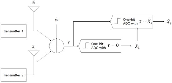
Figure 1.
Proposed scheme.
Without loss of generality, can be detected first, followed by at the second stage, as depicted in Figure 1. The achievable rate of transmitter 1 and 2 can be obtained as follows.
Lemma 1.
Suppose that and are obtained by BPSK signaling and the one-bit ADC at the first stage uses a zero threshold. The error-free achievable rate of transmitter 1, which is denoted as , is given by
where and denote binary entropy and Gaussian Q-function, respectively, and is the average transmit power of for . Moreover, in the derivation, and in (5) correspond to the received SNRs of the signals from transmitters 1 and 2, respectively.
Proof.
See Appendix A. □
Lemma 2.
For a given value of , the error-free achievable rate of transmitter 2 is , when the threshold value is set as at the second stage.
Proof.
Based on the hypothesis of the lemma, let . Since is detected at the second stage, the achievable rate at the second stage can be determined by calculating the mutual information between and . By the definition of in (2), is given by
Thus, if we define as follows, the mutual information between and is equal to the mutual information between and :
In other words, if we define as the one-bit quantized value of obtained using a zero threshold for quantization, then the mutual information between and is equal to the mutual information between and . The mutual information between the input signal and the one-bit quantized output with a zero threshold was derived in Theorem 2 by [16]. It can be expressed as , where represents the binary entropy function and denotes the quantization function. □
From these lemmas, the achievable sum rate of the proposed scheme can be represented by a function of two variables and as follows:
In the following subsections, power allocation problems are considered when we have some transmit power constraints.
3.2. Individual Power Constraints
For simplicity, we call the two transmitters and , and denote their respective transmit signals as and . In this subsection, we consider the case when the two transmitters have individual power constraints and , where and are independent deterministic constants. We must identify the case that achieves a higher achievable rate between the two cases and ; the former is the case where the signal of transmitter is first detected, and the latter is the case where the signal of transmitter is first detected (we assumed in the previous section that the signal denoted as is detected first). Considering that upper bounds and are independent, we can assume that without loss of generality.
Let and be the maximum sum rates corresponding to the cases and , respectively. For any given , in (5) is an increasing function of . Thus, we have
and the maximum sum rate with individual power constraints is given as
Remark 1.
The Gaussian Q-function can be closely approximated by a linear function as near , such that if x and y are sufficiently small, we may use the approximation , where the approximation error converges to zero as x and y approaches 0. Therefore, in a low SNR regime, we may approximate as , such that and are achieved at and and have the same approximated values. Thus, .
Remark 2.
In (5), if , then . Given that is a fast-decreasing function, the rate is rapidly saturated to an upper bound that is smaller than when and increase. Hence, if and are moderately large, then detecting the signal with a higher transmit power is more advantageous, such that can be increased up to 2 with increasing and .
Thus, Remark 1 implies that, in a low SNR regime, the detection order in the proposed scheme is not significant. In addition, Remark 2 suggests that in moderate and high SNR regimes, it is more advantageous to detect the transmit signal with higher transmit power at the first stage. That is, is generally preferred when .
Therefore, can be approximated as . Finally, an optimal value of must be determined. However, has multiple critical points with respect to , making it difficult to mathematically determine the optimal value. Instead, we can numerically determine optimal through offline simulation in the AWGN channel. The corresponding results can be utilized as a lookup table to determine optimal values for wireless fading channels, as described in the following sections.
3.3. Total Power Constraint
In this subsection, we consider the case when the sum power is upper-bounded by a constant, such as . The maximization problem is defined as
The domain of interest for the maximization is given by the colored region (the union of light and dark gray regions) in Figure 2, whose boundary is described by , , and . In the previous subsection, we explained that the first detection of the transmit signal with higher transmit power is more advantageous. Hence, we can claim that the optimal transmit powers and will exist in the region (light gray-colored region in Figure 2) with a high probability. If (within the dark gray-colored region), then the sum rate is less than the optimal rate (the rate is saturated to the upper bound of , as discussed in Remark 2). For any given , is an increasing function of . Thus, the optimal value will exist in the rightmost boundary of the light-gray region and the optimization problem can be modified as
where the region for maximization corresponds to the arrow depicted in Figure 2.
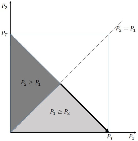
Figure 2.
Domain for optimization.
In practice, an optimal value of (for a given value of , is also deterministic as at the optimal point) can be numerically obtained through offline simulation in the AWGN channel as a function of . The corresponding result can be used as a lookup table to determine an optimal power allocation in realistic fading channels, as is demonstrated in the following section. This type of approach is similar to the usage of SNR versus block error rate lookup table (evaluated in the AWGN channel) to determine an appropriate modulation and coding set in long-term evolution standards.
4. Extension to Complex Fading Channels
In practice, a baseband digital communication channel is generally given by a complex fading channel. One of the most popular examples is the Rayleigh fading channel which is widely used to model wireless communication channels. In a narrow-band fading environment, two-transmitter and single-receiver AWGN MAC with fading can be expressed as
where and are random variables that model fading channels between transmitters and the receiver. In the Rayleigh fading environment, and are modeled as complex circularly symmetric Gaussian random variables, and is complex white Gaussian noise that has zero mean and unit variance and is also circularly symmetric.
If the CSIs and are known at the transmitter, then transmitter can equalize the phase of the corresponding channel by transmitting , where denotes the phase of , for . Considering and are complex baseband signals, we can directly extend the proposed scheme to the rotated quadrature phase shift keying (QPSK) signaling for each (assuming individually imposing BPSK signals for real and imaginary parts) [17]. With QPSK signaling and phase equalization at the transmitter, the received signal can be rewritten as
Here, we investigate the real and imaginary parts separately, which can be presented as follows:
where and represent the real and imaginary parts of a complex number, respectively. Thus, we have two equivalent real-valued channels from the complex baseband channel. Given that a QPSK signal has the same signal powers at real and imaginary parts, and . In addition, the real and imaginary parts of have half-variance of . Therefore, the real and imaginary channels in (16) can be represented as
where , , and . Then, we can individually apply Lemmas 1 and 2 for real () and imaginary () channels, respectively, to obtained the instantaneous sum rate of the proposed scheme. That is, the instantaneous sum rate of the proposed scheme with QPSK signaling for and is given by
The transmit power multiplied by channel gain can be regarded as an effective SNR. If we have a total power constraint, then the optimization problem is derived from (12) and (18) as:
5. Numerical Results
5.1. AWGN MAC without Channel Fading
In this subsection, we present simulation results for the AWGN MAC without fading, as described in (1). Figure 3 serves as a verification of Lemma 2, which was discussed in Section 3. The parameter r in the figure represents the transmit power ratio, defined as , where . The dashed lines with square markers (labeled as “Analysis” in the figure) depict the graphs of the analysis results, specifically , as derived in Lemma 2. On the other hand, the solid lines with cross markers (labeled as “Simulation” in the figure) represent the average mutual information between and , which quantifies the achievable rate at the second stage. The simulation results align with the analysis results as presented in Lemma 2, irrespective of the power ratio between the transmitters.
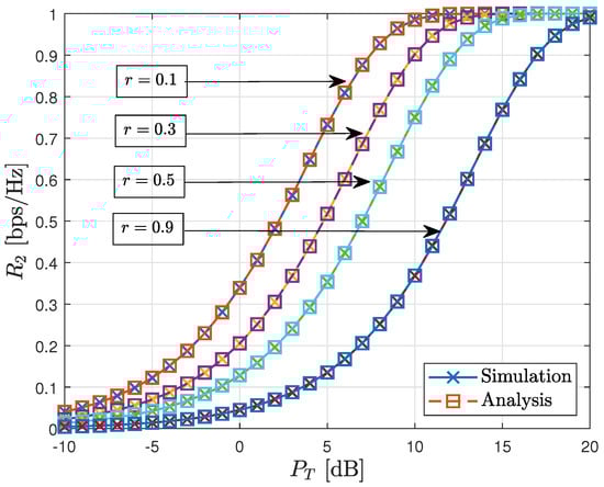
Figure 3.
Verification for Lemma 2.
In Figure 4, we present the achievable sum rates of the proposed scheme in the AWGN MAC for various power ratios (r). As anticipated in Remark 2, it is observed that at high SNR, the maximum achievable sum rate is 2 bps/Hz when the power ratio r is appropriately selected. In the figure, it can be generally observed that for a given total transmit power (), the maximum sum rate is attained when , as anticipated in Section 3.3. It is important to note that the optimal value of r varies depending on the total transmit power.
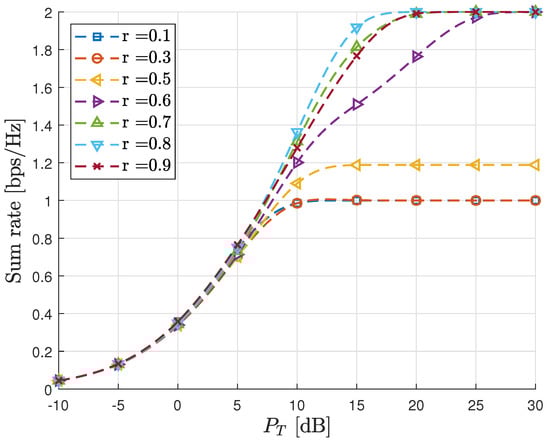
Figure 4.
Sum rate vs. in AWGN MAC.
Figure 5 illustrates the sum rate of the proposed scheme as a function of , with fixed at 5 dB. The rate remains independent of due to threshold adaptation, which eliminates interference from . Consequently, the sum rate increases with increasing . In contrast, Figure 6 presents the sum rate of the proposed scheme as a function of , with fixed at 5 dB. Unlike the case in Figure 5, the rate is influenced by , as interference cancellation is not considered in the first stage detection. As a result, the sum rate is significantly lower than that achieved in Figure 5, even though the same total transmit power is used. This observation indirectly highlights the greater importance of the first stage detection.
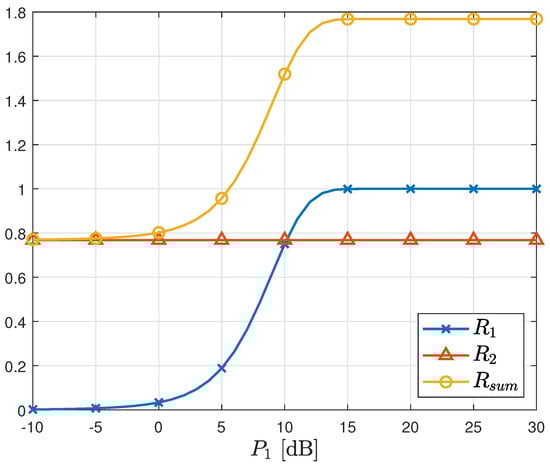
Figure 5.
Sum rate vs. in AWGN MAC. [dB].
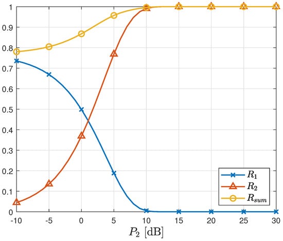
Figure 6.
Sum rate vs. in AWGN MAC. [dB].
5.2. AWGN MAC with Channel Fading
In this subsection, we present simulation results obtained in the AWGN MAC with complex channel fading, as defined in Section 4 of this study. As depicted in Figure 4, the sum rate of the proposed method is found to be sensitive to the power ratio between the received signals, calculated as in the AWGN MAC. Consequently, in the case of the AWGN MAC, an optimal power ratio can be determined through offline simulations conducted over a suitable range of with adequate resolution. However, when considering fading channels, the received signal power ratio, calculated as , is also influenced by the channel gains. Since the range of is the set of positive real numbers, it is practically infeasible to perform offline simulations for all possible combinations of the ratio . Therefore, an optimal power allocation strategy that is applicable in practical scenarios is required to address the challenges associated with fading channels.
For simplicity, the variances of and are normalized to 1 in this subsection. To obtain the optimal power allocation in fading channels, we use a lookup table-based approach, as described in the previous sections. The lookup is constructed through an offline simulation in the AWGN channel described in Section 2 and Section 3. For simple description, the power ratio r is defined such that and . We want to determine an optimal power ratio for each realization of channel values using the AWGN lookup table. The lookup table saves the sum rate as a function of two variables r and . In this simulation, the lookup table is established under the assumptions , , and their quantization precision is .
Then, we use the lookup table to determine the optimal value of in (19) for given and as follows:
- Using the same values of r with the lookup table, we use and as candidates for optimal power allocation. However, this ratio cannot be directly used as an input for the lookup table. This is because, the effective powers (transmit powers multiplied by the channel gains) are used as input values for in fading channels as described in (19), which are different from those in the AWGN channel. Thus, we need to calculate the effective power ratio: and for each r, and then use these ratios as an input for the lookup table.
- Similarly, the input SNR for the lookup table must also be modified to an effective value. For given and , the maximum effective SNR is given by in decibel scale.
- For each r, the effective ratios , , and the effective SNR (in dB) are now obtained. By using two pairs and as input pairs for the lookup table, we can obtain two expected sum rates for each r. The value of r that corresponds to the maximum value of provides the optimal power allocation.
Figure 7 demonstrates the advantage of determining optimal power allocation for each channel realization. This type of adaptive power allocation achieves a considerable gain compared with the cases using fixed power ratios which is independent of channel realizations. In Figure 7, each dashed line represents the sum rates () obtained using a fixed power ratio (r) selected from the set . As observed in the figure, the sum rate increases with r at very high SNR, but this trend diminishes at moderate SNR levels. Thus, it is evident that an appropriate power allocation strategy can further enhance the achievable rate, as previously discussed in Figure 4. The solid line in the figure represents the sum rate achieved using the proposed adaptive power allocation algorithm. By selecting an optimal power distribution based on the given channel realizations, the proposed algorithm globally achieves the maximum sum rate across various SNR levels.
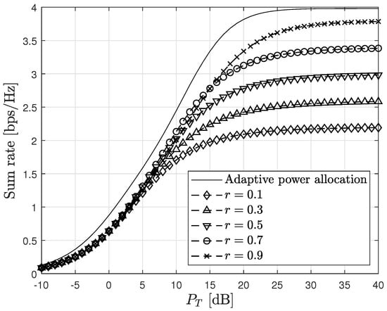
Figure 7.
Adaptive power allocation for fading channels.
Figure 8 compares the performance of the proposed scheme with the conventional scheme [32], where the conventional scheme represents the achieved capacity assuming perfect CSIR in normal two-transmitter MAC (4) with one-bit ADCs at the receiver. The proposed scheme can achieve twofold higher spectral efficiency than the conventional scheme and the SISO channel capacity [17] at high SNR because it can successfully remove non-orthogonal interference in MAC. In contrast, the spectral efficiency of the conventional scheme is upper-bounded by the same limit as the SISO channel capacity, due to the non-orthogonal interference, which cannot be eliminated in the DSP domain when one-bit ADCs are used at the receiver.
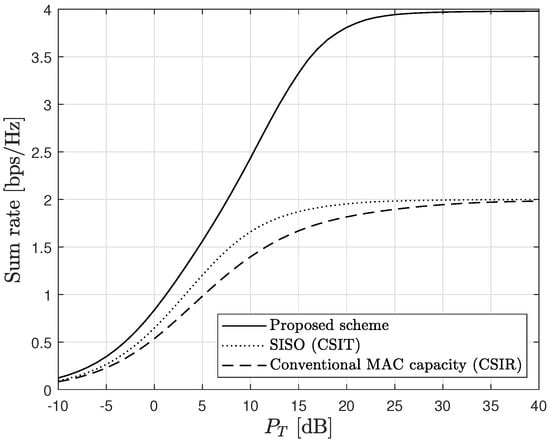
Figure 8.
Comparison with conventional results.
The conventional scheme [32] in Figure 8 (dashed line, which depicts (4)) is derived considering perfect CSI only at the receiver. Therefore, the corresponding spectral efficiency is smaller than the SISO capacity derived assuming perfect CSIT (dotted line, which depicts (3)). Nevertheless, we use this conventional scheme [32] for comparison purposes because the capacity achieving signaling with perfect CSIT is unknown [31]. Although the gap in the amount of available CSIT imposes a disadvantage to the conventional scheme, the important thing is that the capacity available in the normal MAC structure is saturated to the same upper bound with the SISO capacity when one-bit ADCs are used at the receiver, regardless of the amount of CSIT [31]. Nonlinear ISI between different transmitters cannot sufficiently be mitigated with the conventional MAC structure when the receiver uses one-bit ADCs. The saturation phenomenon observed in the conventional normal MAC structure is inevitable even with perfect CSIT [31], because the presence of nonlinear ISI induced by one-bit quantization in the receiving RF chain is independent of CSIT. The proposed scheme overcomes this limitation by employing analog domain threshold adaptation, which effectively mitigates the nonlinear ISI mentioned above. As a result, the proposed scheme achieves a twofold higher sum rate compared to conventional methods.
6. Conclusions
In this study, we propose a novel analog-domain interference cancellation scheme for a two-transmitter MAC with one-bit ADCs. Unlike the conventional MAC structure, our proposed scheme enables the implementation of a non-orthogonal multiple access structure that is compatible with one-bit ADCs through the use of an appropriate threshold adaptation-based interference cancellation method. With our proposed scheme, the corresponding two-transmitter MAC structure achieves a twofold higher spectral efficiency, even when the total transmit power is fixed. This increase is significant because it was previously unattainable using digital-domain signal processing due to the detrimental nonlinear distortion introduced by one-bit ADCs, which severely affects interference cancellation. However, our proposed scheme overcomes this limitation by applying a novel threshold adaptation technique in the analog domain.
In our study, we initially demonstrated that the capacity of a one-bit-quantized channel with fixed interference can be made equivalent to the capacity of a one-bit-quantized channel without interference by appropriately setting the threshold value equal to the interference level. This result allowed us to perform successive detection of the two transmitter’s signals in a sequential manner. While the first detected signal may experience some interference from the other signal, the second detection can be performed without interference, assuming that the first detection is accurate. This sequential detection approach led us to conclude that the accuracy of the first stage detection is more crucial than the second detection. We took this insight into account when deriving an optimal power allocation strategy while satisfying the total power constraint. The main advantage of our proposed scheme stems from its ability to effectively mitigate non-orthogonal interference between the two transmit signals. By exploiting the successive interference cancellation capability, our scheme enables improved signal detection and communication performance. Additionally, our study revealed that the achievable rate of the proposed scheme is highly dependent on the power ratio between the two transmitters, especially in wireless fading environments. To tackle this challenge, we derived an appropriate power allocation strategy aimed at maximizing the achievable sum rate. The proposed power allocation algorithm is based on a lookup table approach, which is constructed through offline simulations in AWGN channels. The algorithm determines an optimal power allocation for given realizations of channel gains, leading to a significant increase in the sum rate of the proposed system. This approach allows us to adapt the power allocation dynamically based on the specific channel conditions, thereby maximizing the overall system performance.
Through a combination of simulations and analysis, our study demonstrated that the proposed scheme, along with its accompanying power allocation strategy, leads to a substantial enhancement in the total spectral efficiency compared to conventional schemes. This improvement offers a promising approach to enhance the performance of a two-transmitter Gaussian MAC system utilizing one-bit ADCs. Furthermore, the results obtained in this study can serve as a foundation for extending the proposed scheme to scenarios involving multiple transmitters beyond just two. In the case of multiple transmitters, it is expected that the achievable sum rate will increase linearly with the number of transmitters. However, this would require the utilization of additional RF chains to facilitate the proposed threshold adaptation process. By employing more RF chains, the system can effectively manage the interference and achieve higher overall spectral efficiency. It is important to note that the scalability of the proposed scheme to multiple transmitters introduces additional complexity in terms of hardware requirements and implementation considerations. However, the potential benefits in terms of increased sum rate make it a worthwhile avenue for further exploration and research.
Author Contributions
Conceptualization, M.M. and T.-K.K.; methodology, M.M.; software, M.M. and J.-I.K.; validation, M.M., J.-I.K. and T.-K.K.; formal analysis, M.M. and T.-K.K.; investigation, M.M., J.-I.K. and T.-K.K.; resources, T.-K.K.; data curation, M.M. and J.-I.K.; writing—original draft preparation, M.M.; writing—review and editing, M.M., J.-I.K., and T.-K.K.; visualization, M.M.; supervision, T.-K.K.; project administration, M.M. and T.-K.K.; funding acquisition, M.M. and T.-K.K. All authors have read and agreed to the published version of the manuscript.
Funding
The work of Moonsik Min was supported in part by the National Research Foundation of Korea (NRF) Grant funded by the Korea government (MSIT) (No. 2023R1A2C1004034), and in part by the BK21 FOUR Project funded by the Ministry of Education, Korea (4199990113966). The work of Tae-Kyoung Kim was supported by the National Research Foundation of Korea (NRF) grant funded by the Korea government (MIST) (No. 2021R1F1A1063273).
Institutional Review Board Statement
Not applicable.
Informed Consent Statement
Not applicable.
Data Availability Statement
Not applicable.
Conflicts of Interest
The authors declare no conflict of interest.
Appendix A. Proof of Lemma 1
From the relation between the capacity and mutual information, is given by
where and denotes the entropy of a random variable. Given that is binary and , and W are symmetric, we have . Furthermore,
where and calculated as:
By substituting (A3) into (A2), we obtain
where (a) follows because and and represent the sample spaces of and , respectively.
References
- Heath, R.W., Jr.; Lozano, A. Foundations of MIMO Communication; Cambridge University Press: Cambridge, UK, 2018. [Google Scholar]
- Tse, D.; Viswanath, P. Fundamentals of Wireless Communication; Cambridge University Press: Cambridge, UK, 2005. [Google Scholar]
- Busari, E.G.; Huq, K.M.S.; Mumtaz, S.; Dai, L.; Rodriguez, J. Millimeter-Wave Massive MIMO Communication for Future Wireless Systems: A Survey. IEEE Commun. Surv. Tutor. 2017, 20, 836–869. [Google Scholar] [CrossRef]
- Larsson, E.G.; Edfors, O.; Tufvesson, F.; Marzetta, T.L. Massive MIMO for next generation wireless systems. IEEE Commun. Mag. 2014, 52, 186–195. [Google Scholar] [CrossRef]
- Swindlehurst, A.L.; Ayanoglu, E.; Heydari, P.; Capolino, F. Millimeter-wave massive MIMO: The next wireless revolution? IEEE Commun. Mag. 2014, 52, 56–62. [Google Scholar] [CrossRef]
- Saleem, A.; Cui, H.; He, Y.; Boag, A. Channel propagation characteristics for massive multiple-input/multiple-output systems in a tunnel environment. IEEE Antennas Propag. Mag. 2022, 64, 126–142. [Google Scholar] [CrossRef]
- Jabbar, A.; Abbasi, Q.H.; Anjum, N.; Kalsoom, T.; Ramzan, N.; Ahmed, S.; Rafi-ul-Shan, P.M.; Falade, O.P.; Imran, M.A.; Ur Rehman, M. Millimeter-Wave Smart Antenna Solutions for URLLC in Industry 4.0 and Beyond. Sensors 2022, 22, 2688. [Google Scholar] [CrossRef]
- Zhang, Z.; Zou, X.; Li, Q.; Wei, N. Towards 100 Gbps over 100 km: System Design and Demonstration of E-Band Millimeter Wave Communication. Sensors 2022, 22, 9514. [Google Scholar] [CrossRef]
- Sejan, M.A.S.; Rahman, M.H.; Shin, B.S.; Oh, J.H.; You, Y.H.; Song, H.K. Machine Learning for Intelligent-Reflecting-Surface-Based Wireless Communication towards 6G: A Review. Sensors 2022, 22, 5405. [Google Scholar] [CrossRef]
- Alraih, S.; Shayea, I.; Behjati, M.; Nordin, R.; Abdullah, N.F.; Abu-Samah, A.; Nandi, D. Revolution or Evolution? Technical Requirements and Considerations towards 6G Mobile Communications. Sensors 2022, 22, 762. [Google Scholar] [CrossRef]
- Hazarika, A.; Rahmati, M. Towards an Evolved Immersive Experience: Exploring 5G- and Beyond-Enabled Ultra-Low-Latency Communications for Augmented and Virtual Reality. Sensors 2023, 23, 3682. [Google Scholar] [CrossRef]
- Hashima, S.; Hatano, K.; Kasban, H.; Mohamed, E.M. Wi-Fi Assisted Contextual Multi-Armed Bandit for Neighbor Discovery and Selection in Millimeter Wave Device to Device Communications. Sensors 2021, 21, 2835. [Google Scholar] [CrossRef]
- Mohamed, E.M.; Hashima, S.; Hatano, K.; Aldossari, S.A. Two-Stage Multiarmed Bandit for Reconfigurable Intelligent Surface Aided Millimeter Wave Communications. Sensors 2022, 22, 2179. [Google Scholar] [CrossRef]
- Walden, R. Analog-to-Digital Converter Survey and Analysis. IEEE J. Select. Areas Commun. 1999, 17, 539–550. [Google Scholar] [CrossRef]
- Zhang, J.; Dai, L.; Li, X.; Liu, Y.; Hanzo, L. On low-resolution ADCs in practical 5G millimeter-wave massive. MIMO systems. IEEE Commun. Mag. 2018, 56, 205–211. [Google Scholar] [CrossRef]
- Singh, J.; Dabeer, O.; Madhow, U. On the limits of communication with low-precision analog-to-digital conversion at the receiver. IEEE Trans. Commun. 2009, 57, 3629–3639. [Google Scholar] [CrossRef]
- Mo, J.; Heath, R.W., Jr. Capacity Analysis of One-Bit Quantized MIMO Systems with Transmitter Channel State Information. IEEE Trans. Signal Process. 2015, 63, 5498–5512. [Google Scholar] [CrossRef]
- Mo, J.; Alkhateeb, A.; Abu-Surra, S.; Heath, R.W., Jr. Hybrid architectures with few-bit ADC receivers: Achievable rates and energy-rate tradeoffs. IEEE Trans. Wirel. Commun. 2017, 16, 2274–2287. [Google Scholar] [CrossRef]
- Mo, J.; Heath, R.W., Jr. Limited feedback in single and multi-user MIMO systems with finite-bit ADCs. IEEE Trans. Wirel. Commun. 2018, 17, 3284–3297. [Google Scholar] [CrossRef]
- Nam, Y.; Do, H.; Jeon, Y.-S.; Lee, N. On the Capacity of MISO Channels with One-Bit ADCs and DACs. IEEE J. Sel. Areas Commun. 2019, 37, 2132–2145. [Google Scholar] [CrossRef]
- Nam, S.H.; Lee, S.H. Secrecy Capacity of a Gaussian Wiretap Channel With ADCs is Always Positive. IEEE Trans. Inf. Theory. 2022, 68, 1186–1196. [Google Scholar] [CrossRef]
- Jeon, Y.-S.; Do, H.; Hong, S.-N.; Lee, N. Soft-Output Detection Methods for Sparse Millimeter Wave MIMO Systems with Low-Precision ADCs. IEEE Trans. Commun. 2019, 67, 2822–2836. [Google Scholar] [CrossRef]
- Kim, T.K. Improved Likelihood Probability in MIMO Systems Using One-Bit ADCs. Sensors 2023, 23, 5542. [Google Scholar] [CrossRef]
- Choi, J.; Mo, J.; Heath, R.W., Jr. Near Maximum-Likelihood Detector and Channel Estimator for Uplink Multiuser Massive MIMO Systems with One-Bit ADCs. IEEE Trans. Commun. 2016, 64, 2005–2018. [Google Scholar] [CrossRef]
- Jacobsson, S.; Durisi, G.; Coldrey, M.; Gustavsson, U.; Studer, C. Throughput analysis of massive MIMO uplink with low-resolution ADCs. IEEE Trans. Wirel. Commun. 2017, 16, 4038–4051. [Google Scholar] [CrossRef]
- Kim, T.K. Cooperative DF Protocol for MIMO Systems Using One-Bit ADCs. Sensors 2022, 22, 7843. [Google Scholar] [CrossRef] [PubMed]
- Li, R.; Zhao, L.; Liu, C.; Bi, M. Strongest Angle-of-Arrival Estimation for Hybrid Millimeter Wave Architecture with 1-Bit A/D Equipped at Transceivers. Sensors 2022, 22, 3140. [Google Scholar] [CrossRef]
- Ge, S.; Fan, C.; Wang, J.; Huang, X. Low-Complexity One-Bit DOA Estimation for Massive ULA with a Single Snapshot. Remote Sens. 2022, 14, 3436. [Google Scholar] [CrossRef]
- Zhao, W.; Chen, X. Zero-Delay Joint Source Channel Coding for a Bivariate Gaussian Source over the Broadcast Channel with One-Bit ADC Front Ends. Entropy 2021, 23, 1679. [Google Scholar] [CrossRef]
- Xiao, Z.; Zhao, J.; Liu, T.; Geng, L.; Zhang, F.; Tong, J. On the Energy Efficiency of Massive MIMO Systems With Low-Resolution ADCs and Lattice Reduction Aided Detectors. Synmmetry 2020, 12, 406. [Google Scholar] [CrossRef]
- Rassouli, B.; Varasteh, M.; Gunduz, D. Capacity Region of a One-Bit Quantized Gaussian Multiple Access Channel. In Proceedings of the 2017 IEEE International Symposium on Information Theory (ISIT), Aachen, Germany, 25–30 June 2017. [Google Scholar]
- Ranjbar, M.; Tran, N.H.; Vu, M.N.; Nguyen, T.V.; Gursoy, M.C. Capacity Region and Capacity-Achieving Signaling Schemes for 1-bit ADC Multiple Access Channels in Rayleigh Fading. IEEE Trans. Wirel. Commun. 2020, 19, 6162–6178. [Google Scholar] [CrossRef]
- Rahman, M.H.; Ranjbar, M.; Tran, N.H.; Pham, K. Optimal Signaling Schemes of 2-User Gaussian Mixture Multiple-Access Channels with 1-bit ADC. In Proceedings of the MILCOM 2021—2021 IEEE Military Communications Conference (MILCOM), San Diego, CA, USA, 29 November–2 December 2021; pp. 13–18. [Google Scholar]


Disclaimer/Publisher’s Note: The statements, opinions and data contained in all publications are solely those of the individual author(s) and contributor(s) and not of MDPI and/or the editor(s). MDPI and/or the editor(s) disclaim responsibility for any injury to people or property resulting from any ideas, methods, instructions or products referred to in the content. |
© 2023 by the authors. Licensee MDPI, Basel, Switzerland. This article is an open access article distributed under the terms and conditions of the Creative Commons Attribution (CC BY) license (https://creativecommons.org/licenses/by/4.0/).