
A Study on the Optimal Magnetic Beam Forming of Coil Arrays for Long Distance Wireless Power Transmission


Abstract
:1. Introduction
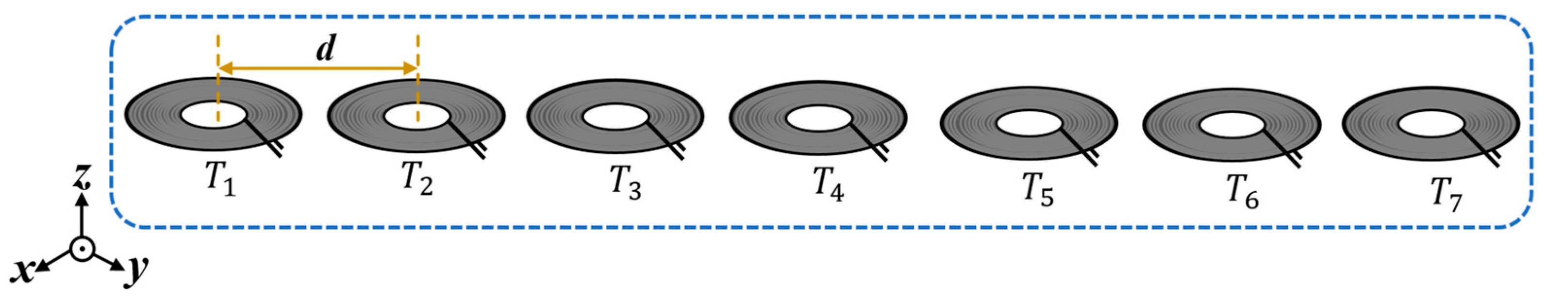
2. MIMO-WPT System Modelling and Analysis
2.1. Analysis of MIMO-WPT Using the Conventional Phase-Calculation Method Based on the Phased-Array Concept
2.2. MIMO-WPT Based on the Proposed Phase-Calculation Method
3. Experimental Results and Analysis
3.1. Experimental Results for MIMO-WPT Based on the Conventional Beam-Steering Phase-Control Method
3.2. Experimental Results for MIMO-WPT Based on the Proposed Phase-Calculation Method
4. Conclusion
Author Contributions
Funding
Institutional Review Board Statement
Informed Consent Statement
Data Availability Statement
Conflicts of Interest
References
- Shan, D.; Wang, H.; Cao, K.; Zhang, J. Wireless Power Transfer System with Enhanced Efficiency by Using Frequency Reconfigurable Metamaterial. Sci. Rep. 2022, 12, 331. [Google Scholar] [CrossRef] [PubMed]
- Musavi, F.; Eberle, W. Overview of Wireless Power Transfer Technologies for Electric Vehicle Battery Charging. IET Power Electron. 2014, 7, 60–66. [Google Scholar] [CrossRef]
- Sample, A.P.; Meyer, D.A.; Smith, J.R. Analysis, Experimental Results, and Range Adaptation of Magnetically Coupled Resonators for Wireless Power Transfer. IEEE Trans. Ind. Electron. 2011, 58, 544–554. [Google Scholar] [CrossRef]
- Zhang, J.; Wang, F. Efficiency Analysis of Multiple-Transmitter Wireless Power Transfer Systems. Int. J. Antennas Propag. 2018, 2018, 3415239. [Google Scholar] [CrossRef]
- Zhang, Z.; Pang, H.; Georgiadis, A.; Cecati, C. Wireless Power Transfer—An Overview. IEEE Trans. Ind. Electron. 2019, 66, 1044–1058. [Google Scholar] [CrossRef]
- Lyu, Y.-L.; Meng, F.-Y.; Yang, G.-H.; Che, B.-J.; Wu, Q.; Sun, L.; Erni, D.; Li, J.L.-W. A Method of Using Nonidentical Resonant Coils for Frequency Splitting Elimination in Wireless Power Transfer. IEEE Trans. Power Electron. 2015, 30, 6097–6107. [Google Scholar] [CrossRef]
- Aoki, T.; Yuan, Q.; Quang-Thang, D.; Okada, M.; Hsu, H.-M. Maximum Transfer Efficiency of MIMO-WPT System. In Proceedings of the 2018 IEEE Wireless Power Transfer Conference (WPTC), Montreal, QC, Canada, 3–7 June 2018; IEEE: Piscataway, NJ, USA; pp. 1–3. [Google Scholar]
- Ahn, D.; Hong, S. Effect of Coupling between Multiple Transmitters or Multiple Receivers on Wireless Power Transfer. IEEE Trans. Ind. Electron. 2013, 60, 2602–2613. [Google Scholar] [CrossRef]
- Johari, R.; Krogmeier, J.V.; Love, D.J. Analysis and Practical Considerations in Implementing Multiple Transmitters for Wireless Power Transfer via Coupled Magnetic Resonance. IEEE Trans. Ind. Electron. 2014, 61, 1774–1783. [Google Scholar] [CrossRef]
- OSSIA WHITEPAPER, “COTA vs Other Wireless Power Technologies”. Available online: https://f.hubspotusercontent30.net/hubfs/2870932/Content%20Offers/Whitepapers/Cota%20vs%20Other%20Wireless%20Power%20Technologies.pdf (accessed on 3 July 2022).
- Energous Corporation, “Energous Breakthrough FCC Approval for 15W WattUp PowerBridge, Increases Wireless Power Networks Charging Capability by 15 Times”. Available online: https://d1io3yog0oux5.cloudfront.net/_a782aabe56d720829907c6508bd8b733/energous/news/2022-08-10_Energous_Breakthrough_FCC_Approval_For_15W_WattUp__732.pdf (accessed on 3 July 2022).
- Josh Constine, “uBeam Declassifies Secrets to Try to Prove Wireless Power Is Possible”. Available online: https://techcrunch.com/2015/11/07/wireless-power-charger/ (accessed on 3 July 2022).
- Jadidian, J.; Katabi, D. Magnetic MIMO: How To Charge Your Phone in Your Pocket. In Proceedings of the 20th Annual International conference on Mobile Computing and Networking, Maui, HI, USA, 7–11 September 2014; pp. 495–506. [Google Scholar]
- Huang, Y.; Boyle, K. Antennas: From Theory to Practice; John Wiley & Sons: Nashville, TN, USA, 2008; ISBN 9780470772928. [Google Scholar]
- Gao, L.; Hu, W.; Wu, Z.; Deng, Q.; Xie, X.; Zhou, H.; Luo, S. Magnetic coupling resonant wireless energy transmission coil quantitative relation modeling and simulation research. In Proceedings of the 2013 10th IEEE International Conference on Control and Automation (ICCA), Hangzhou, China, 12–14 June 2013. [Google Scholar]
- Maxwell 3D Ansys ® Electronics Desktop Release 2022 R2. (ANSYS Inc., 2022). Available online: https://www.ansys.com (accessed on 3 January 2023).
- Van Thuan, N.; Kang, S.H.; Choi, J.H.; Jung, C.W. Magnetic Resonance Wireless Power Transfer Using Three-Coil System with Single Planar Receiver for Laptop Applications. IEEE Trans. Consum. Electron. 2015, 61, 160–166. [Google Scholar] [CrossRef]

| Phase Step (ψ) | Azimuth (xy-Plane) | Elevation (yz-Plane) |
|---|---|---|
| 0° |  |  |
| 30° |  | 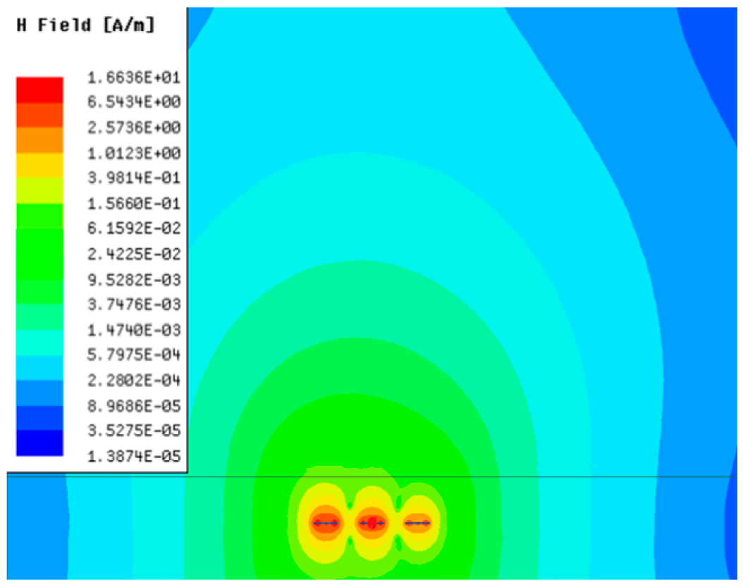 |
| 60° | 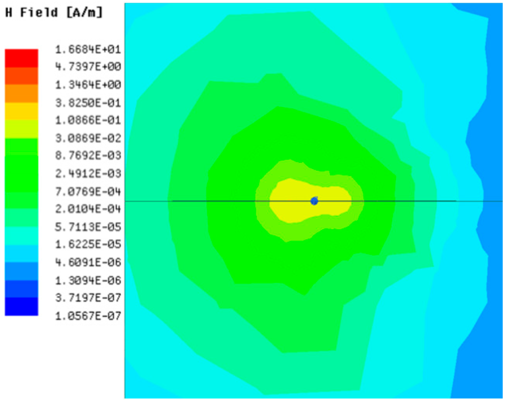 | 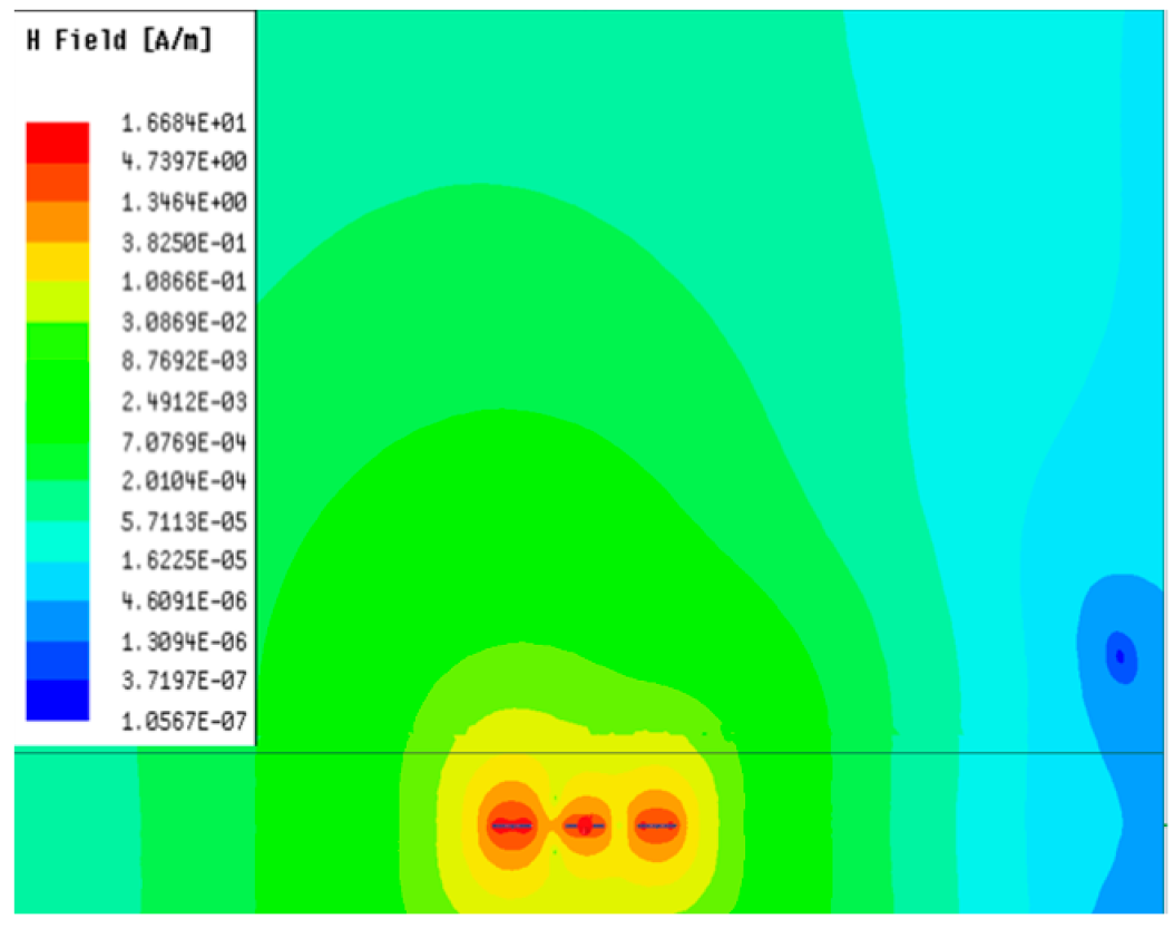 |
| 90° |  | 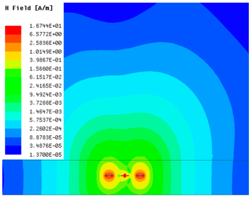 |
| Phase Step (ψ) | Azimuth (xy-Plane) | Elevation (yz-Plane) |
|---|---|---|
| 0° | 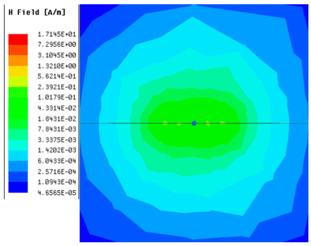 | 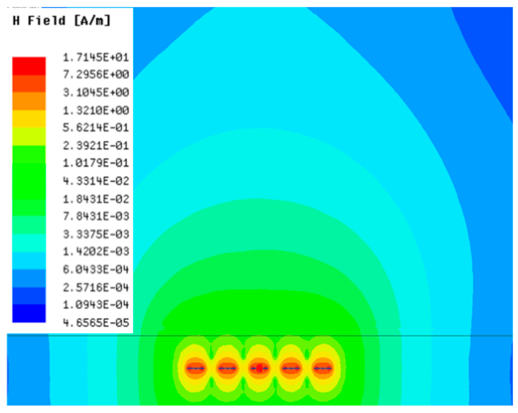 |
| 30° | 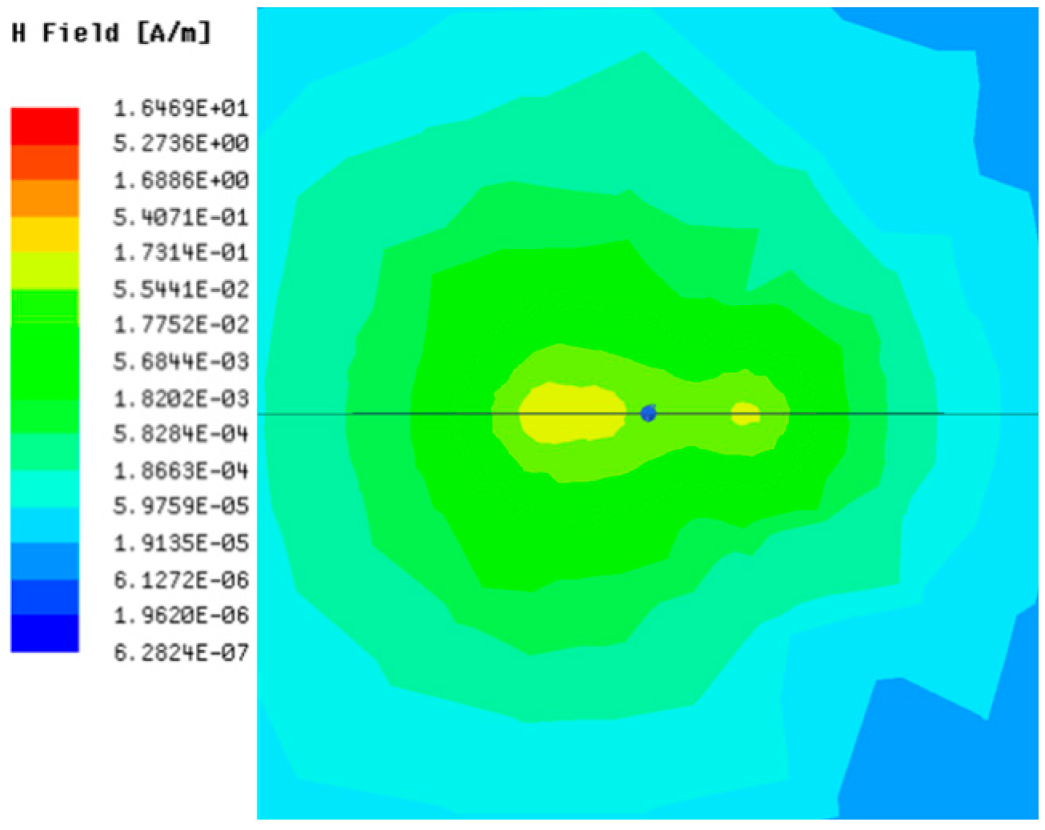 | 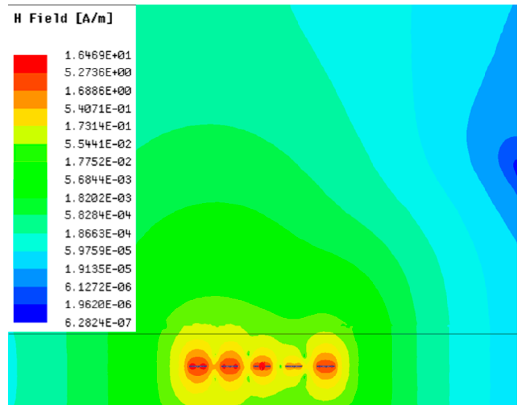 |
| 60° |  |  |
| 90° |  |  |
| Phase Step (ψ) | Azimuth (xy-Plane) | Elevation (yz-Plane) |
|---|---|---|
| 0° |  |  |
| 30° |  |  |
| 60° |  |  |
| 90° |  |  |
Disclaimer/Publisher’s Note: The statements, opinions and data contained in all publications are solely those of the individual author(s) and contributor(s) and not of MDPI and/or the editor(s). MDPI and/or the editor(s) disclaim responsibility for any injury to people or property resulting from any ideas, methods, instructions or products referred to in the content. |
© 2023 by the authors. Licensee MDPI, Basel, Switzerland. This article is an open access article distributed under the terms and conditions of the Creative Commons Attribution (CC BY) license (https://creativecommons.org/licenses/by/4.0/).
Share and Cite
Oh, M.-J.; Danuor, P.; Jung, Y.-B. A Study on the Optimal Magnetic Beam Forming of Coil Arrays for Long Distance Wireless Power Transmission. Sensors 2023, 23, 5312. https://doi.org/10.3390/s23115312
Oh M-J, Danuor P, Jung Y-B. A Study on the Optimal Magnetic Beam Forming of Coil Arrays for Long Distance Wireless Power Transmission. Sensors. 2023; 23(11):5312. https://doi.org/10.3390/s23115312
Chicago/Turabian StyleOh, Myeong-Jun, Patrick Danuor, and Young-Bae Jung. 2023. "A Study on the Optimal Magnetic Beam Forming of Coil Arrays for Long Distance Wireless Power Transmission" Sensors 23, no. 11: 5312. https://doi.org/10.3390/s23115312
APA StyleOh, M.-J., Danuor, P., & Jung, Y.-B. (2023). A Study on the Optimal Magnetic Beam Forming of Coil Arrays for Long Distance Wireless Power Transmission. Sensors, 23(11), 5312. https://doi.org/10.3390/s23115312