
The MAPS: Toward a Novel Mobility Assistance System for Visually Impaired People


Abstract
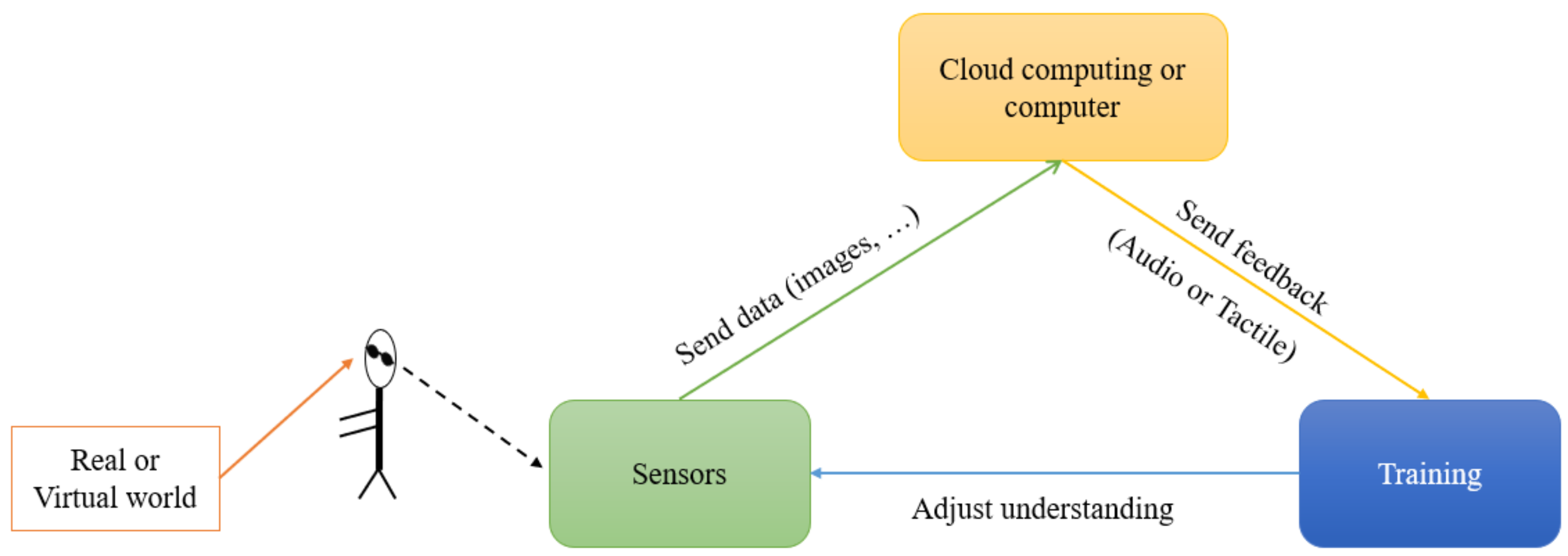
:1. Introduction
2. State of the Art on SSDs
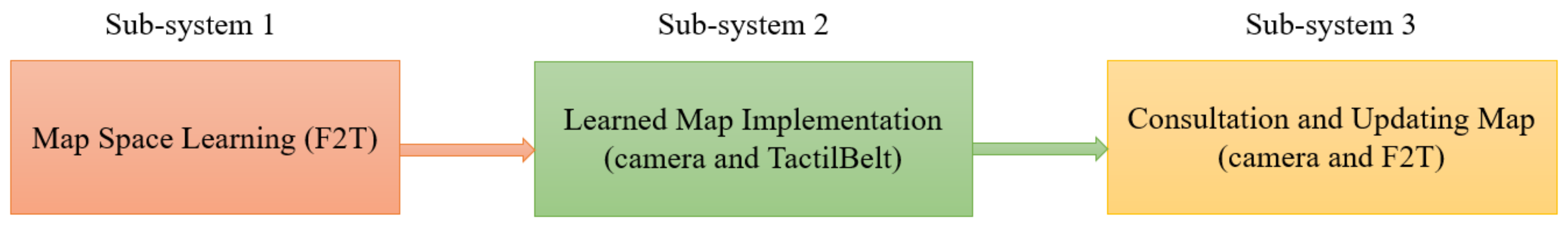
3. The MAPS, a Novel System for VIP Mobility Assistance
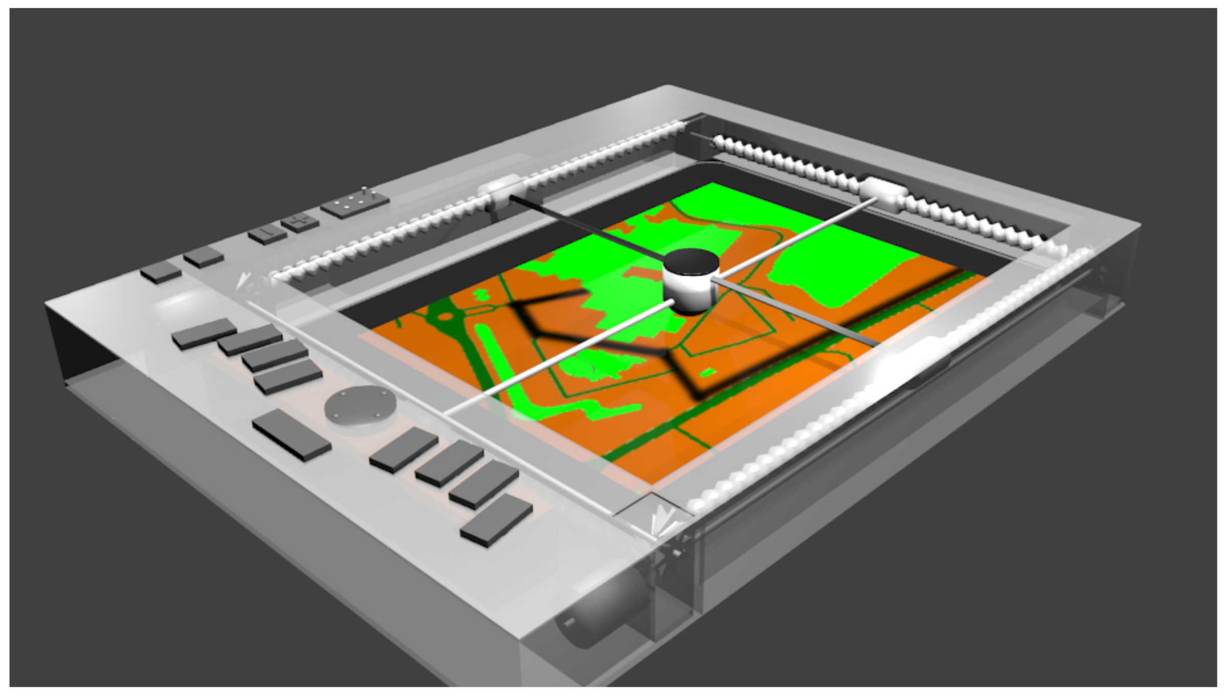
3.1. Feedback 1: Map Space Learning
- -
- Friction feedback: The F2T can simulate both solid and fluid friction, allowing different textures to be presented.
- -
- Elevation feedback: This effect can be used to simulate slopes and bas-relief elements. A high elevation difference also allows edge simulations, making it possible to follow the shape of an object.
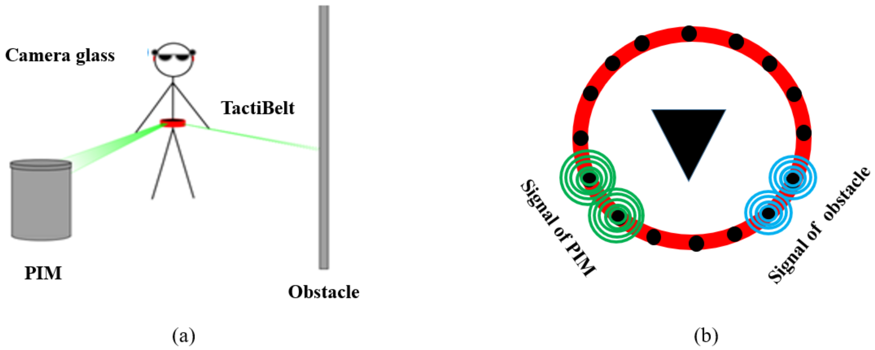
3.2. Feedback 2: Effective Displacement Using TactiBelt
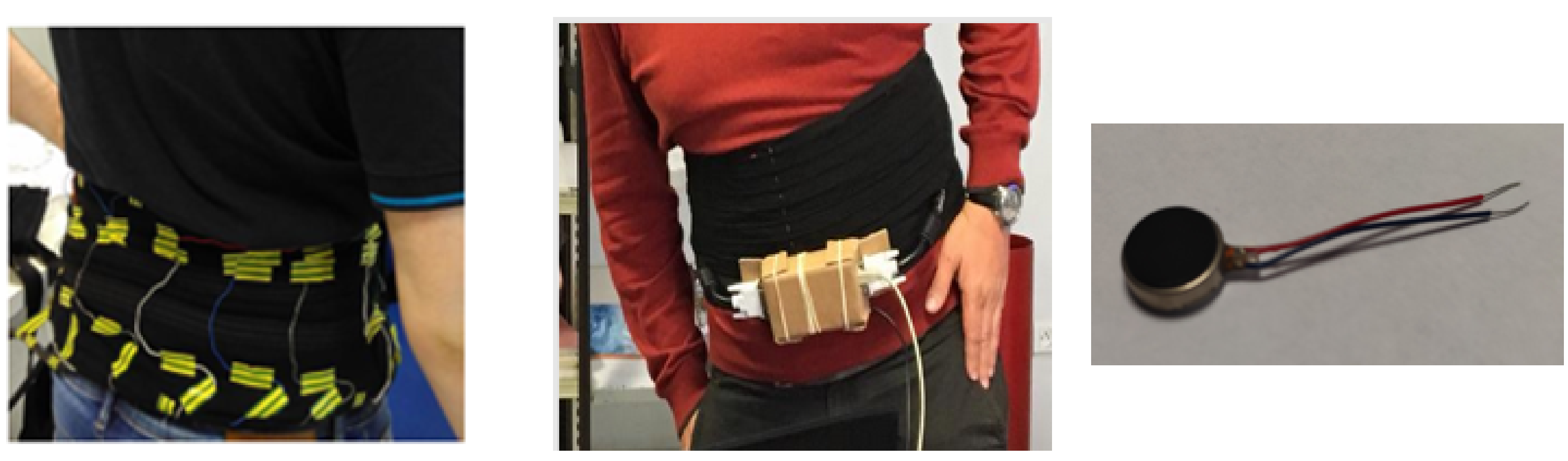
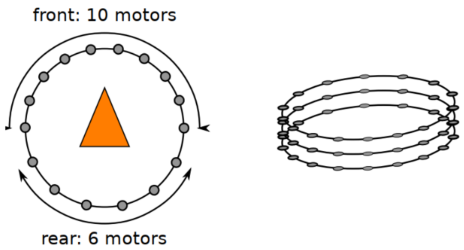
4. TactiBelt Hardware Design
4.1. The TactiBelt Operative Part
4.2. The TactiBelt Control Part
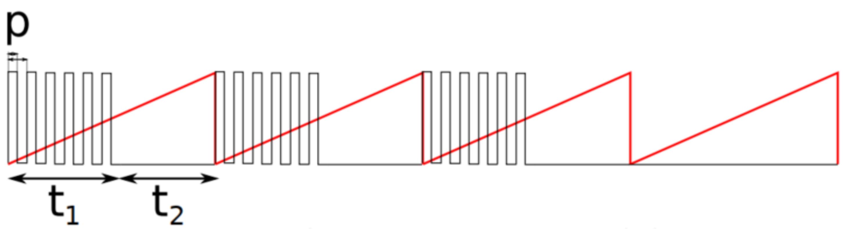
- -
- The power “p”, characterizing the amplitude of the vibrations, controlled with a high-frequency PWM;
- -
- The duration “”, corresponding to the duration at the high state of the pulses;
- -
- The duration “”, characterizing the duration at the low state of the pulsations. Note that if = 0 or = 0, the vibration will be continuous;
- -
- The parameter “n”, specifying the number of pulses; if n = 0, the pulsation will not stop.
5. Experimental Evaluation of TactiBelt
5.1. Perception of Direction and Strength of the Stimuli
5.1.1. Check the Technical Quality of Generated Stimuli
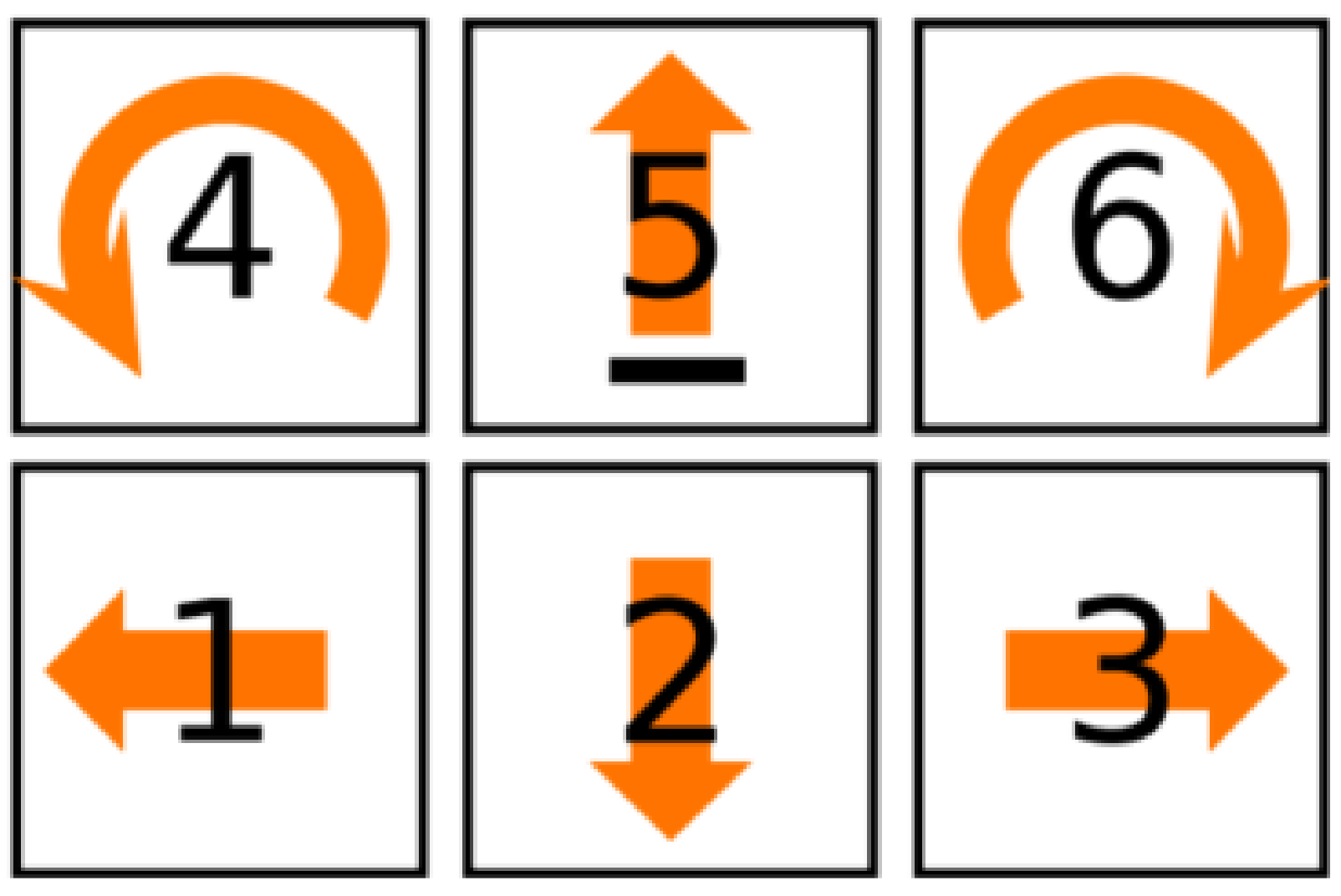
5.1.2. Perception of Direction
Task
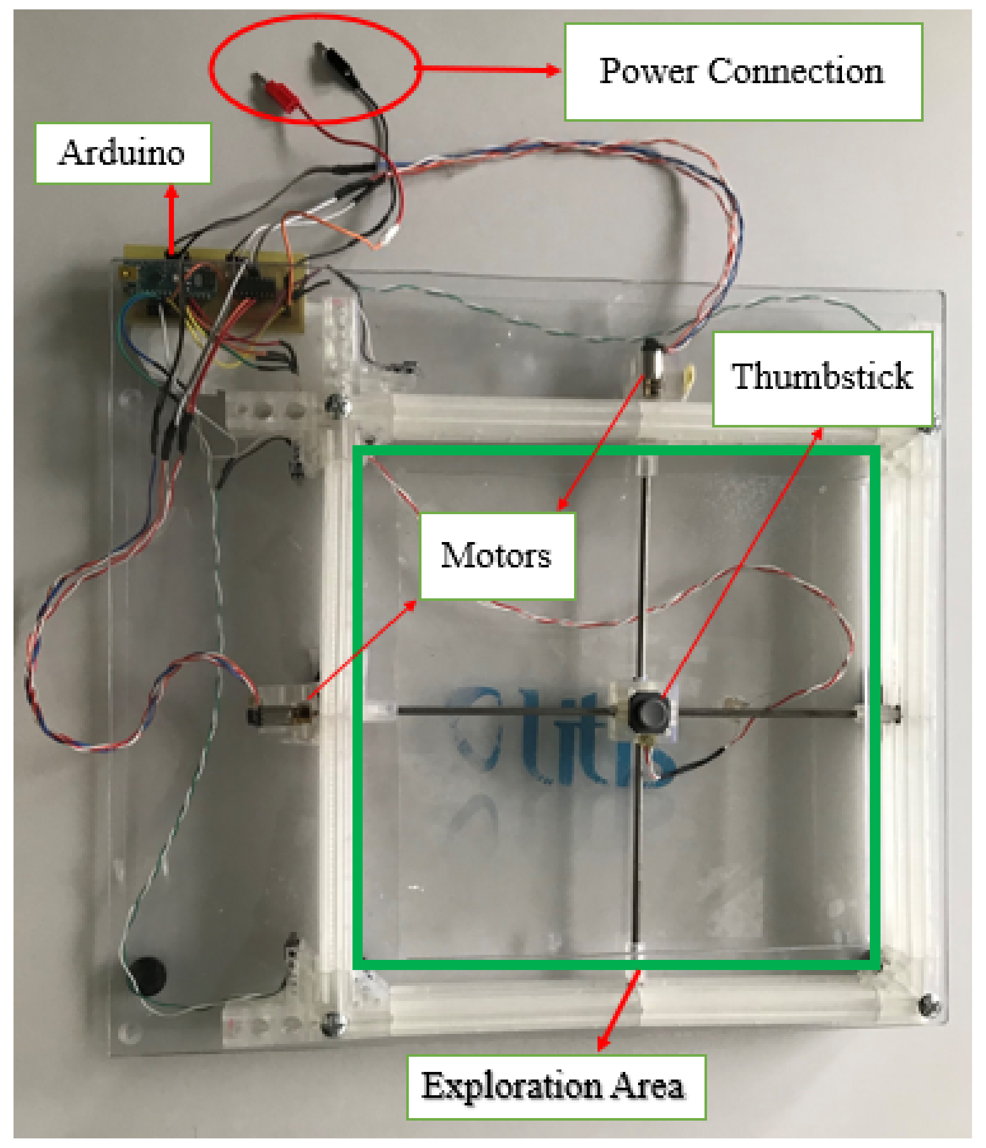
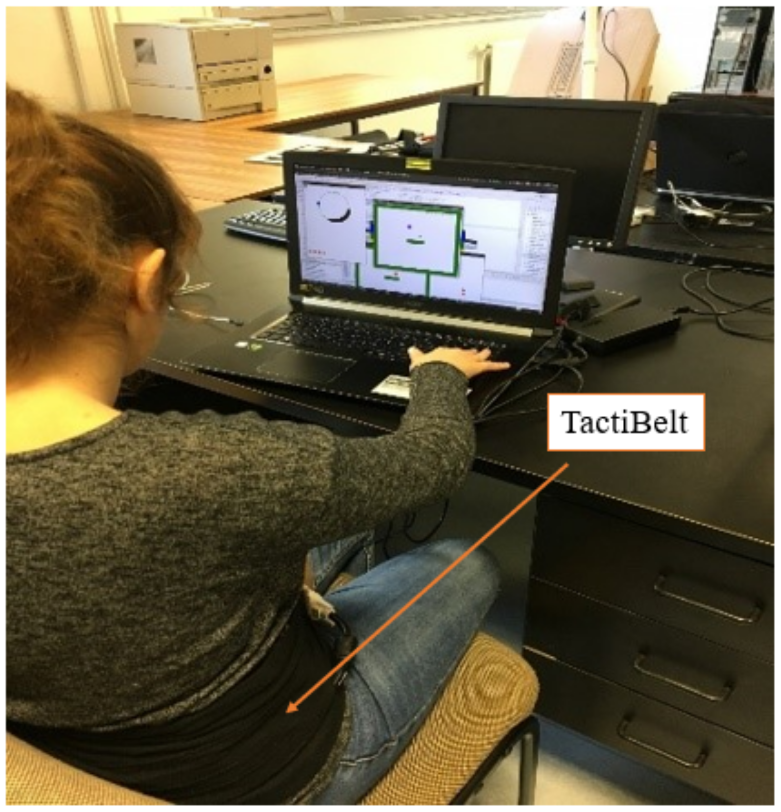
Experimental Platform
Experimental Protocol
Collected Data
Discussion
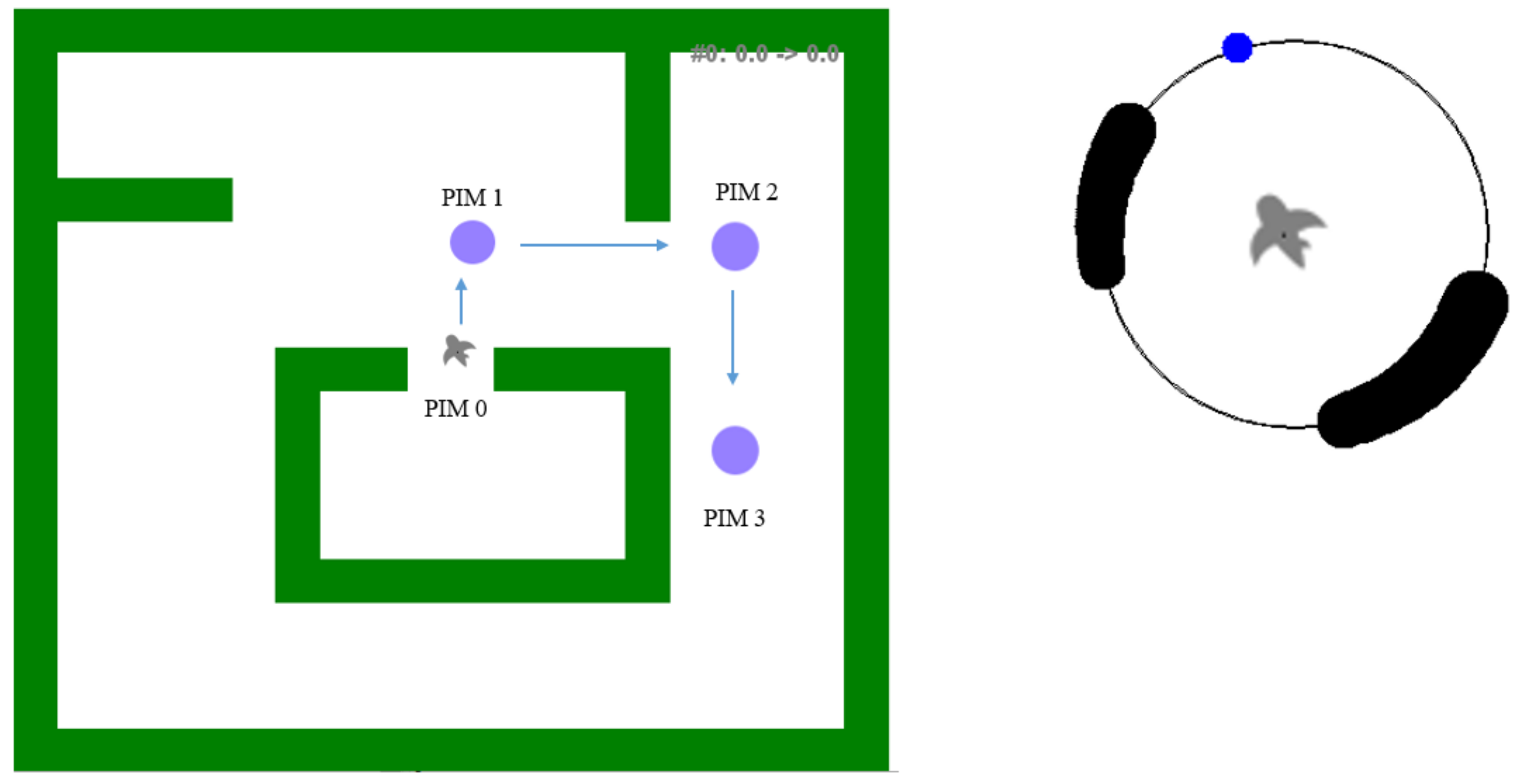
5.2. Navigation in the Simulated (Virtual) Environment
Task
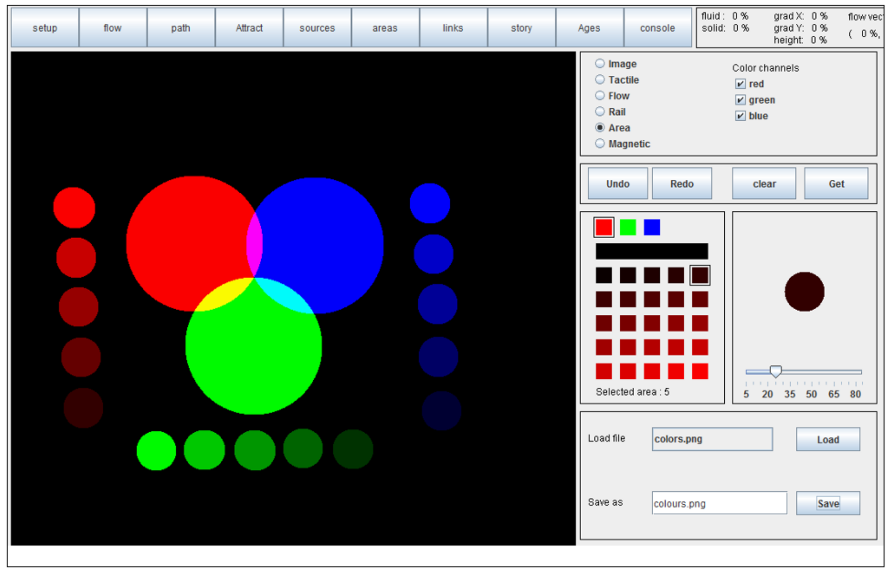
Experimental Platform
Experimental Protocol
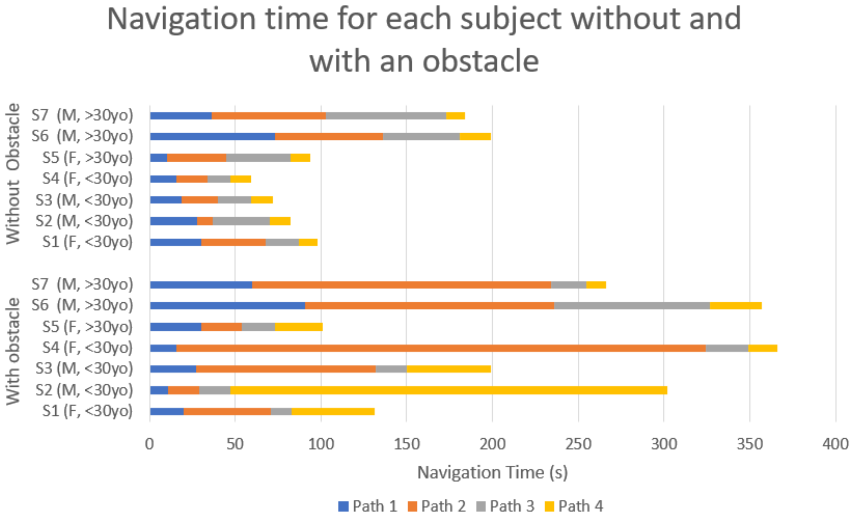
Collected Data
Discussion
Conclusion of Two Experiences
6. Conclusions
- -
- To learn a map and thus to construct the mental map of the environment where the VIP will navigate (using F2T);
- -
- To transfer the “learned map” into a physical displacement (using the TactiBelt and its accessories).
Author Contributions
Funding
Institutional Review Board Statement
Informed Consent Statement
Data Availability Statement
Acknowledgments
Conflicts of Interest
Abbreviations
| VIP | Visually Impaired People |
| MAPS | Mobility Assistance Path Planning and orientation in Space |
| SSDs | Sensory Substitution Devices |
| PIM | Points of Interest for Mobility |
| TDU | Tongue Display Unit |
| F2T | Force Feedback Tablet |
| PWM | Pulse Width Modulation |
References
- Bach-y-Rita, P.; Kercel, S.W. Sensory substitution and the human-machine interface. Trends Cogn. Sci. 2003, 7, 541–546. [Google Scholar] [CrossRef] [PubMed]
- Bach-y-Rita, P.; Collins, C.C.; Saunders, F.A.; White, B.; Scadden, L. Vision substitution by tactile image projection. Nature 1969, 221, 963–964. [Google Scholar] [CrossRef] [PubMed]
- Auvray, M.; Hanneton, S.; O’Regan, J.K. Learning to perceive with a visuo-auditory substitution system: Localisation and object recognition with The vOICe. Perception 2007, 36, 416–430. [Google Scholar] [CrossRef] [PubMed]
- Spence, C. The skin as a medium for sensory substitution. Multisens. Res. 2014, 27, 293–312. [Google Scholar] [CrossRef]
- Schinazi, V.R.; Thrash, T.; Chebat, D.R. Spatial navigation by congenitally blind individuals. Wiley Interdiscip Rev Cogn Sci. 2016, 7, 37–58. [Google Scholar] [CrossRef] [Green Version]
- Chebat, D.R.; Maidenbaum, S.; Amedi, A. Navigation using sensory substitution in real and virtual mazes. PLoS ONE 2015, 10, e0126307. [Google Scholar] [CrossRef] [Green Version]
- Chebat, D.R.; Schneider, F.C.; Kupers, R.; Ptito, M. Navigation with a sensory substitution device in congenitally blind individuals. Neuroreport 2011, 22, 342–347. [Google Scholar] [CrossRef]
- Kupers, R.; Chebat, D.R.; Madsen, K.H.; Paulson, O.B.; Ptito, M. Neural correlates of virtual route recognition in congenital blindness. Proc. Natl. Acad. Sci. USA 2010, 107, 12716–12721. [Google Scholar] [CrossRef] [Green Version]
- Segond, H.; Weiss, D.; Sampaio, E. Human spatial navigation via a visuo-tactile sensory substitution system. Perception 2005, 34, 1231–1249. [Google Scholar] [CrossRef]
- Montello, D.; Sas, C. Human Factors of Wayfinding in Navigation. In International Encyclopedia of Ergonomics and Human Factors, 2nd ed.; CRC Press: Boca Raton, FL, USA, 2006; Volume 3. [Google Scholar] [CrossRef] [Green Version]
- Marston, J.R.; Church, R.L. A relative access measure to identify barriers to efficient transit use by persons with visual impairements. Disabil. Rehabil. 2005, 27, 769–779. [Google Scholar] [CrossRef]
- Patla, A.E.; Vickers, J.N. Where and when do we look as we approach and step over an obstacle in the travel path? Neuroreport 1997, 8, 3661–3665. [Google Scholar] [CrossRef]
- Patla, A.E.; Prentice, S.D.; Gobbi, L.T. Visual Control of Obstacle Avoidance during Locomotion: Strategies in Young Children, Young and Older Adults. Adv. Psychol. 1996, 114, 257–277. [Google Scholar] [CrossRef]
- Gori, M.; Cappagli, G.; Tonelli, A.; Baud-Bovy, G.; Finocchietti, S. Devices for visually impaired people: High technological devices with low user acceptance and no adaptability for children. Neurosci. Biobehav. Rev. 2016, 69, 79–88. [Google Scholar] [CrossRef] [Green Version]
- Elmannai, W.; Elleithy, K. Sensor-based assistive devices for visually-impaired people: Current status, challenges, and future directions. Sensors 2017, 17, 565. [Google Scholar] [CrossRef] [Green Version]
- Brown, D.J.; Simpson, A.J.R.; Proulx, M.J. Visual objects in the auditory system in sensory substitution: How much information do we need? Multisens. Res. 2014, 27, 337–357. [Google Scholar] [CrossRef] [Green Version]
- Brown, D.; Macpherson, T.; Ward, J. Seeing with sound? Exploring different characteristics of a visual-to-auditory sensory substitution device. Perception 2011, 40, 1120–1135. [Google Scholar] [CrossRef] [Green Version]
- Striem-Amit, E.; Guendelman, M.; Amedi, A. Visual’ Acuity of the Congenitally Blind Using Visual-To-Auditory Sensory Substitution. PLoS ONE 2012, 7, e33136. [Google Scholar] [CrossRef]
- Abboud, S.; Hanassy, S.; Levy-Tzedek, S.; Maidenbaum, S.; Amedi, A. EyeMusic: Introducing a ‘visual’ colorful experience for the blind using auditory sensory substitution. Restor. Neurol. Neurosci. 2014, 32, 247–257. [Google Scholar] [CrossRef] [Green Version]
- Meijer, P.B.L. An Experimental System for Auditory Image Representations. IEEE Trans. Biomed. Eng. 1992, 39, 112–121. [Google Scholar] [CrossRef]
- Loomis, J. Sensory Substitution for Orientation and Mobility: What Progress Are We Making? Found. Orientat. Mobility 2010, 1, 7–10. [Google Scholar]
- Maidenbaum, S.; Abboud, S.; Amedi, A. Sensory substitution: Closing the gap between basic research and widespread practical visual rehabilitation. Neurosci. Biobehav. Rev. 2014, 41, 3–15. [Google Scholar] [CrossRef] [Green Version]
- Hoffmann, R.; Spagnol, S.; Kristjánsson, Á.; Unnthorsson, R. Evaluation of an Audio-haptic Sensory Substitution Device for Enhancing Spatial Awareness for the Visually Impaired. Optom. Vis. Sci. 2018, 95, 757–765. [Google Scholar] [CrossRef]
- Ptito, M.; Moesgaard, S.M.; Gjedde, A.; Kupers, R. Cross-modal plasticity revealed by electrotactile stimulation of the tongue in the congenitally blind. Brain 2005, 128, 606–614. [Google Scholar] [CrossRef] [Green Version]
- Arditi, A.; Tian, Y.L. User interface preferences in the design of a camera-based navigation and wayfinding aid. J. Vis. Impair. Blind. 2013, 107, 118–129. [Google Scholar] [CrossRef]
- Elli, G.V.; Benetti, S.; Collignon, O. Is there a future for sensory substitution outside academic laboratories? Multisens. Res. 2014, 27, 271–291. [Google Scholar] [CrossRef]
- Chebat, D.-R.; Harrar, V.; Kupers, R.; Maidenbaum, S.; Amedi, A.; Ptito, M. Sensory Substitution and the Neural Correlates of Navigation in Blindness. In Mobility of Visually Impaired People: Fundamentals and ICT Assistive Technologies; Pissaloux, E., Velazquez, R., Eds.; Springer: Cham, Switzerland, 2018; pp. 167–200. [Google Scholar]
- Ward, J.; Meijer, P. Visual experiences in the blind induced by an auditory sensory substitution device. Conscious. Cogn. 2010, 19, 492–500. [Google Scholar] [CrossRef]
- Buchs, G.; Maidenbaum, S.; Amedi, A.; Levy-Tzedek, S. Virtually zooming-in with sensory substitution for blind users. In Proceedings of the 2015 International Conference on Virtual Rehabilitation (ICVR), Valencia, Spain, 9–12 June 2015; pp. 133–134. [Google Scholar] [CrossRef]
- Gay, S.; Pissaloux, E.; Romeo, K.; Truong, N.T. F2T: A Novel Force-Feedback Haptic Architecture Delivering 2D Data to Visually Impaired People. IEEE Access 2021, 9, 94901–94911. [Google Scholar] [CrossRef]
- Duarte, B.; McDaniel, T.; Chowdhury, A.; Gill, S.; Panchanathan, S. HaptWrap: Augmenting Non-Visual Travel via Visual-to-Tactile Mapping of Objects in Motion. In Proceedings of the 2nd Workshop on Multimedia for Accessible Human Computer Interfaces (MAHCI’19); ACM: New York, NY, USA, 2019; pp. 17–24. [Google Scholar] [CrossRef]
- Bhatlawande, S.; Sunkari, A.; Mahadevappa, M.; Mukhopadhyay, J.; Biswas, M.; Das, D.; Gupta, S. Electronic bracelet and vision-enabled waist-belt for mobility of visually impaired people. Assist. Technol. 2014, 26, 186–195. [Google Scholar] [CrossRef] [PubMed]
- Brown, F.E.; Sutton, J.; Yuen, H.M.; Green, D.; Van Dorn, S.; Braun, T.; Cree, A.J.; Russell, S.R.; Lotery, A.J. A novel, wearable, electronic visual aid to assist those with reduced peripheral vision. PLoS ONE 2019, 14, e0223755. [Google Scholar] [CrossRef] [PubMed]
- Pissaloux, E.; Velazquez, R.; Maingreaud, F. A New Framework for Cognitive Mobility of Visually Impaired Users and Associated Tactile Device. IEEE Trans. Hum.-Mach. Syst. 2017, 47, 1040–1051. [Google Scholar] [CrossRef]
- Gay, S.; Le Run, K.; Pissaloux, E.; Romeo, K.; Lecomte, C. Toward a Predictive Bio-Inspired Navigation Model. Information 2021, 12, 100. [Google Scholar] [CrossRef]
- Corniani, G.; Saal, H.P. Tactile innervation densities across the whole body. J. Neurophysiol. 2020, 124, 1229–1240. [Google Scholar] [CrossRef] [PubMed]
- Arth, K. Neuromorphic Sensory Substitution with an Asynchronous Tactile Belt for Unsighted People: From Design to Clinical Trials. Ph.D. Thesis, Automatic Sorbonne Université, Paris, France, 2018. [Google Scholar]
- Martens, J.; Antonenko, P.D. Narrowing gender-based performance gaps in virtual environment navigation. Comput. Hum. Behav. 2012, 28, 809–819. [Google Scholar] [CrossRef]


| Subjects | Gender | Age |
|---|---|---|
| 1 | F | 24 |
| 2 | M | 22 |
| 3 | M | 25 |
| 4 | F | 24 |
| 5 | F | 68 |
| 6 | M | 48 |
| 7 | M | 40 |
Publisher’s Note: MDPI stays neutral with regard to jurisdictional claims in published maps and institutional affiliations. |
© 2022 by the authors. Licensee MDPI, Basel, Switzerland. This article is an open access article distributed under the terms and conditions of the Creative Commons Attribution (CC BY) license (https://creativecommons.org/licenses/by/4.0/).
Share and Cite
Romeo, K.; Pissaloux, E.; Gay, S.L.; Truong, N.-T.; Djoussouf, L. The MAPS: Toward a Novel Mobility Assistance System for Visually Impaired People. Sensors 2022, 22, 3316. https://doi.org/10.3390/s22093316
Romeo K, Pissaloux E, Gay SL, Truong N-T, Djoussouf L. The MAPS: Toward a Novel Mobility Assistance System for Visually Impaired People. Sensors. 2022; 22(9):3316. https://doi.org/10.3390/s22093316
Chicago/Turabian StyleRomeo, Katerine, Edwige Pissaloux, Simon L. Gay, Ngoc-Tan Truong, and Lilia Djoussouf. 2022. "The MAPS: Toward a Novel Mobility Assistance System for Visually Impaired People" Sensors 22, no. 9: 3316. https://doi.org/10.3390/s22093316
APA StyleRomeo, K., Pissaloux, E., Gay, S. L., Truong, N.-T., & Djoussouf, L. (2022). The MAPS: Toward a Novel Mobility Assistance System for Visually Impaired People. Sensors, 22(9), 3316. https://doi.org/10.3390/s22093316