
Sparse-View CT Reconstruction Based on a Hybrid Domain Model with Multi-Level Wavelet Transform


Abstract
:1. Introduction
- On the basis of single domain restoration, a hybrid domain reconstruction model for sparse-view CT is proposed, which consists of a projection completion module in radon domain and an image restoration module in image domain. Wavelet domains of projection data and image data are embedded in two modules respectively to better extract spatial features and recover texture details. Moreover, the proposed model is end-to-end learning through the differentiable FBP operator.
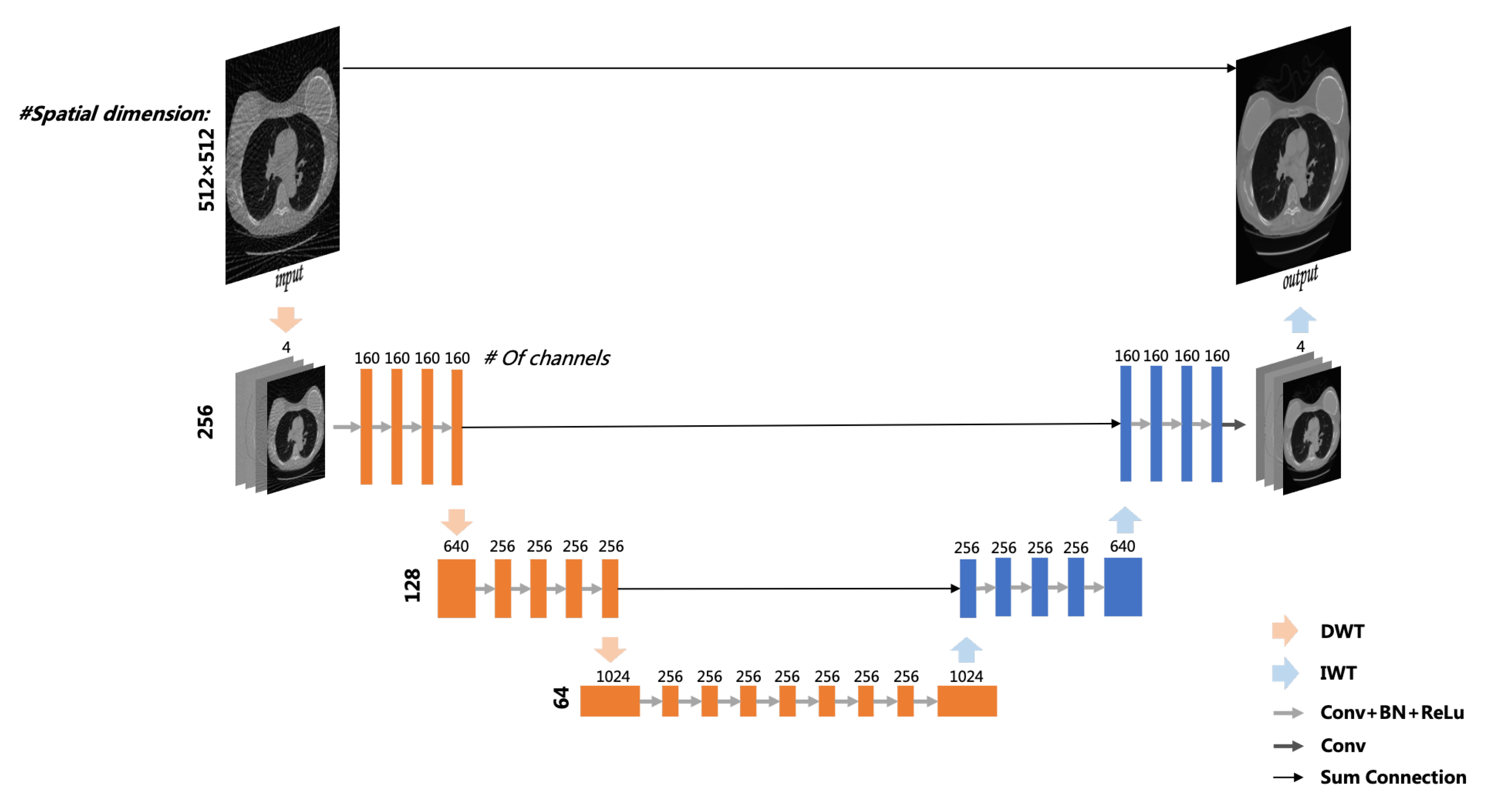
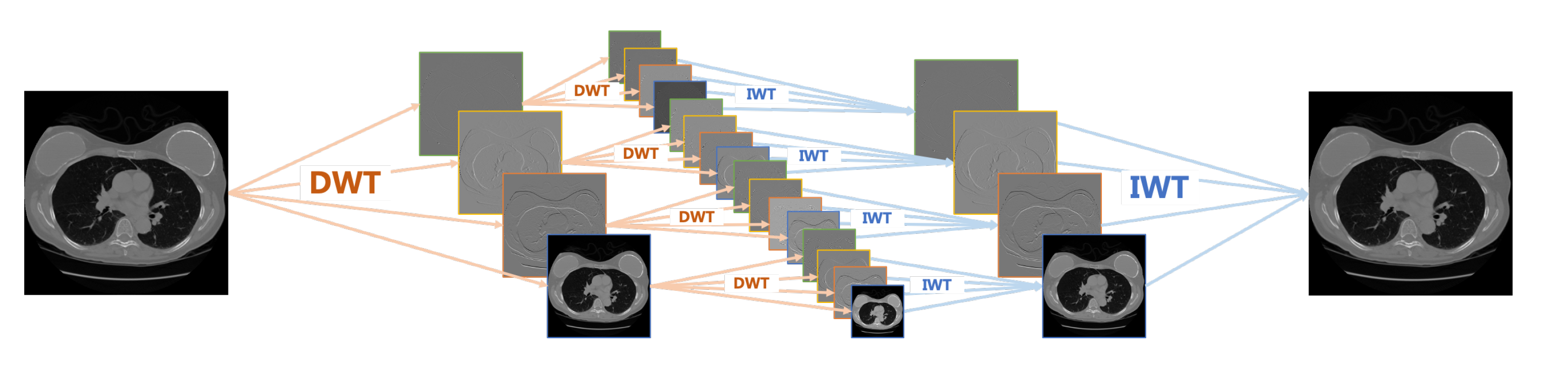
- Multi-level wavelet packet decomposition is utilized to replace the pooling operator and enlarge the effective receptive field. Experimental results have shown that a multi-resolution network with a multi-level wavelet transform can effectively suppress globally distributed streaking artifacts.
- A deep residual learning framework is proposed to learn artifacts. Once the artifacts are estimated, an artifact-free image can be obtained by subtracting the estimated results.
2. Architecture
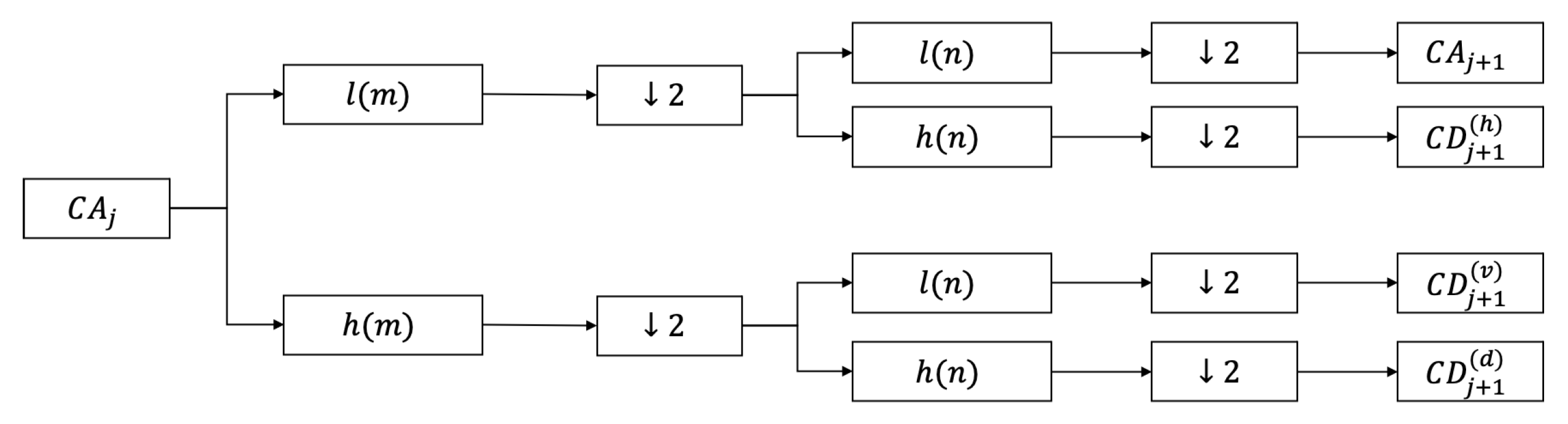
2.1. Wavelet Decomposition
2.2. Reconstruction Model
2.2.1. Deep Learning Network
2.2.2. Relationship between WPT Operator and MWCNN
2.2.3. Hybrid Domain Reconstruction Model
3. Experimental Setting
3.1. Dataset
3.2. Data Simulation
3.3. Network Training
3.4. Image Evaluation
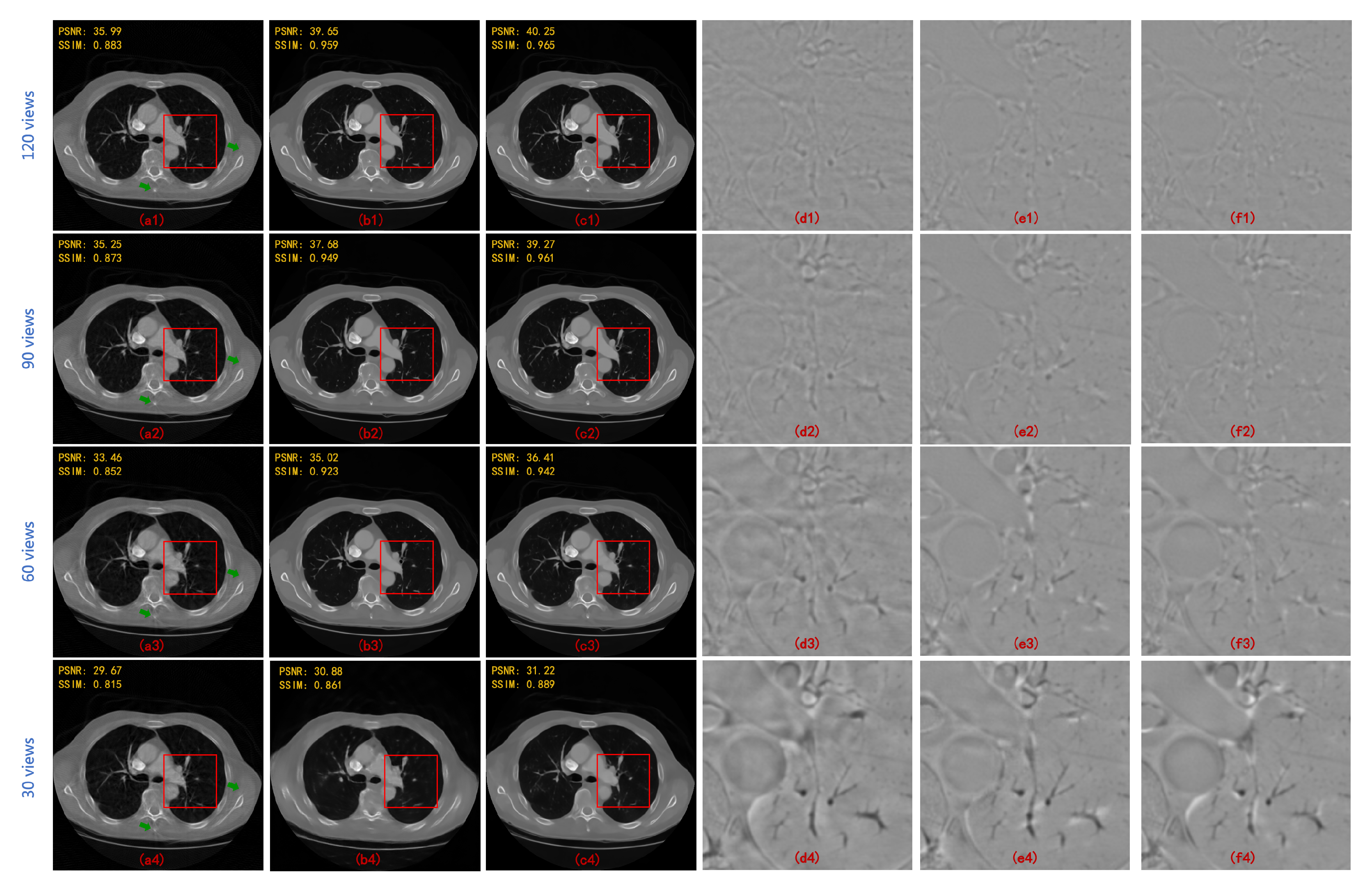
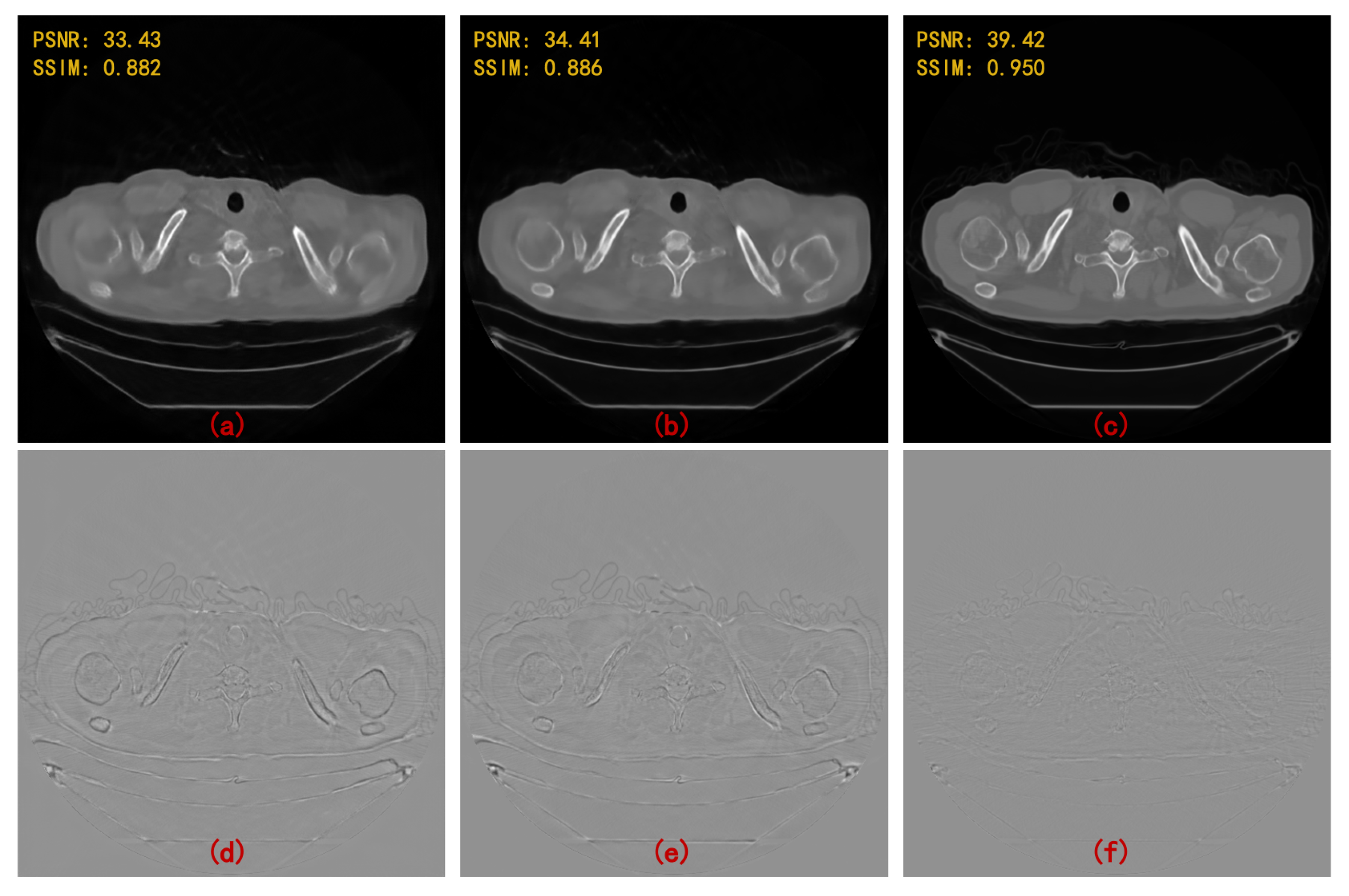
4. Results
5. Discussion and Conclusions
Author Contributions
Funding
Institutional Review Board Statement
Informed Consent Statement
Data Availability Statement
Conflicts of Interest
References
- Tam, K.C. Reducing the fan-beam scanning angular range. Phys. Med. Biol. 1988, 33, 955–967. [Google Scholar] [CrossRef]
- Miller, D.L.; Schauer, D. The ALARA principle in medical imaging. Philosophy 1983, 44, 595–600. [Google Scholar]
- Herman, G.T. Image Reconstruction From Projections. Real-Time Imaging 1995, 1, 3–18. [Google Scholar] [CrossRef]
- Gordon, R. A tutorial on ART (algebraic reconstruction techniques). IEEE Trans. Nucl. Sci. 1974, 21, 78–93. [Google Scholar] [CrossRef]
- Andersen, A.H.; Kak, A.C. Simultaneous Algebraic Reconstruction Technique (SART): A Superior Implementation of the ART Algorithm. Ultrason. Imaging 1984, 6, 81–94. [Google Scholar] [CrossRef] [PubMed]
- Donoho, D.L. Compressed sensing. IEEE Trans. Inf. Theory 2006, 52, 1289–1306. [Google Scholar] [CrossRef]
- Sidky, E.Y.; Kao, C.M.; Pan, X. Accurate image reconstruction from few-views and limited-angle data in divergent-beam CT. J. X-ray Sci. Technol. 2006, 14, 119–139. [Google Scholar]
- Sidky, E.Y.; Pan, X. Image reconstruction in circular cone-beam computed tomography by constrained, total-variation minimization. Phys. Med. Biol. 2008, 53, 4777. [Google Scholar] [CrossRef] [Green Version]
- Wang, S.; Yang, D.M.; Rong, R.; Zhan, X.; Xiao, G. Pathology image analysis using segmentation deep learning algorithms. Am. J. Pathol. 2019, 189, 1686–1698. [Google Scholar] [CrossRef] [Green Version]
- Tian, C.; Fei, L.; Zheng, W.; Xu, Y.; Zuo, W.; Lin, C.W. Deep learning on image denoising: An overview. Neural Netw. 2020, 131, 251–275. [Google Scholar] [CrossRef]
- Zhang, J.; Shao, M.; Yu, L.; Li, Y. Image super-resolution reconstruction based on sparse representation and deep learning. Signal Process. Image Commun. 2020, 115925, 1–10. [Google Scholar] [CrossRef]
- Wang, G. A Perspective on Deep Imaging. IEEE Access 2017, 4, 8914–8924. [Google Scholar] [CrossRef]
- Jin, K.H.; Mccann, M.T.; Froustey, E.; Unser, M. Deep Convolutional Neural Network for Inverse Problems in Imaging. IEEE Trans. Image Process. 2017, 26, 4509–4522. [Google Scholar] [CrossRef] [PubMed] [Green Version]
- Hu, C.; Yi, Z.; Kalra, M.K.; Feng, L.; Yang, C.; Liao, P.; Zhou, J.; Wang, G. Low-Dose CT with a Residual Encoder-Decoder Convolutional Neural Network (RED-CNN). IEEE Trans. Med. Imaging 2017, 36, 2524–2535. [Google Scholar]
- Kang, E.; Chang, W.; Yoo, J.; Ye, J.C. Deep Convolutional Framelet Denosing for Low-Dose CT via Wavelet Residual Network. IEEE Trans. Med. Imaging 2018, 37, 1358–1369. [Google Scholar] [CrossRef] [Green Version]
- Alexandre, G.; Girish, R.; Shuai, L.; Kwabena, A.; Akinwande, A.I.; George, B. High-resolution limited-angle phase tomography of dense layered objects using deep neural networks. Proc. Natl. Acad. Sci. USA 2019, 16, 19848–19856. [Google Scholar]
- Hoyeon, L.; Jongha, L.; Hyeongseok, K.; Byungchul, C.; Seungryong, C. Deep-neural-network-based sinogram synthesis for sparse-view CT image reconstruction. IEEE Trans. Radiat. Plasma Med. Sci. 2018, 3, 109–119. [Google Scholar]
- Edelsbrunner, H.; Harer, J. Persistent homology—A survey. Contemp. Math. 2008, 453, 257–282. [Google Scholar]
- Han, Y.; Yoo, J.; Ye, J.C. Deep residual learning for compressed sensing CT reconstruction via persistent homology analysis. arXiv 2016, arXiv:1611.06391. [Google Scholar]
- Xie, S.; Zheng, X.; Chen, Y.; Xie, L.; Liu, J.; Zhang, Y.; Yan, J.; Zhu, H.; Hu, Y. Artifact Removal using Improved GoogLeNet for Sparse-view CT Reconstruction. Sci. Rep. 2018, 8, 6700. [Google Scholar] [CrossRef] [Green Version]
- Szegedy, C.; Liu, W.; Jia, Y.; Sermanet, P.; Rabinovich, A. Going deeper with convolutions. In Proceedings of the 2015 IEEE Conference on Computer Vision and Pattern Recognition (CVPR), Boston, MA, USA, 7–12 June 2015; pp. 67–74. [Google Scholar]
- Zhang, Z.; Liang, X.; Dong, X.; Xie, Y.; Cao, G. A Sparse-View CT Reconstruction Method Based on Combination of DenseNet and Deconvolution. IEEE Trans. Med. Imaging 2018, 37, 1407–1417. [Google Scholar] [CrossRef] [PubMed]
- Lee, M.; Kim, H.; Kim, H.J. Sparse-view CT reconstruction based on multi-level wavelet convolution neural network. Phys. Med. 2020, 80, 352–362. [Google Scholar] [CrossRef]
- Liu, P.; Zhang, H.; Lian, W.; Zuo, W. Multi-Level Wavelet Convolutional Neural Networks. IEEE Access 2019, 7, 74973–74985. [Google Scholar] [CrossRef]
- Liang, K.; Xing, Y.; Yang, H.; Kang, K. Improve angular resolution for sparse-view CT with residual convolutional neural network. In Proceedings of the Medical Imaging 2018: Physics of Medical Imaging, Houston, TX, USA, 12–15 February 2018; Volume 10573, p. 105731K. [Google Scholar]
- Ghani, M.U.; Karl, W.C. Deep learning-based sinogram completion for low-dose CT. In Proceedings of the 2018 IEEE 13th Image, Video, and Multidimensional Signal Processing Workshop (IVMSP), Aristi Village, Greece, 10–12 June 2018; pp. 1–5. [Google Scholar]
- Jin, S.C.; Hsieh, C.J.; Chen, J.C.; Tu, S.H.; Chen, Y.C.; Hsiao, T.C.; Liu, A.; Chou, W.H.; Chu, W.C.; Kuo, C.W. Development of Limited-Angle Iterative Reconstruction Algorithms with Context Encoder-Based Sinogram Completion for Micro-CT Applications. Sensors 2018, 18, 4458. [Google Scholar] [CrossRef] [Green Version]
- Yuan, H.; Jia, J.; Zhu, Z. SIPID: A deep learning framework for sinogram interpolation and image denoising in low-dose CT reconstruction. In Proceedings of the 2018 IEEE 15th International Symposium on Biomedical Imaging (ISBI 2018), Washington, DC, USA, 4–7 April 2018; pp. 1521–1524. [Google Scholar]
- Lee, D.; Choi, S.; Kim, H.J. High quality imaging from sparsely sampled computed tomography data with deep learning and wavelet transform in various domains. Med. Phys. 2019, 46, 104–115. [Google Scholar] [CrossRef] [PubMed] [Green Version]
- Hu, D.; Liu, J.; Lv, T.; Zhao, Q.; Zhang, Y.; Quan, G.; Feng, J.; Chen, Y.; Luo, L. Hybrid-Domain Neural Network Processing for Sparse-View CT Reconstruction. IEEE Trans. Radiat. Plasma Med. Sci. 2021, 5, 88–98. [Google Scholar] [CrossRef]
- Huang, Z.; Zhang, J.; Zhang, Y.; Shan, H. DU-GAN: Generative Adversarial Networks With Dual-Domain U-Net-Based Discriminators for Low-Dose CT Denoising. IEEE Trans. Instrum. Meas. 2022, 71, 1–12. [Google Scholar] [CrossRef]
- He, B.; Zhang, F.; Zhang, H.; Han, R. A Hybrid Frequency-Spatial Domain Model for Sparse Image Reconstruction in Scanning Transmission Electron Microscopy. In Proceedings of the 2021 IEEE/CVF International Conference on Computer Vision (ICCV), Montreal, QC, Canada, 10–17 October 2021; pp. 2662–2671. [Google Scholar]
- Heil, C.E.; Walnut, D.F. Continuous and discrete wavelet transforms. SIAM Rev. 1989, 31, 628–666. [Google Scholar] [CrossRef] [Green Version]
- Porwik, P.; Lisowska, A. The Haar-wavelet transform in digital image processing: Its status and achievements. Mach. Graph. Vis. 2004, 13, 79–98. [Google Scholar]
- Daubechies, I. The wavelet transform, time-frequency localization and signal analysis. IEEE Trans. Inf. Theory 1990, 36, 961–1005. [Google Scholar] [CrossRef] [Green Version]
- Daubechies, I. Ten lectures on wavelets. J. Acoust. Soc. Am. 1993, 93, 1671. [Google Scholar] [CrossRef]
- Ronneberger, O.; Fischer, P.; Brox, T. U-net: Convolutional networks for biomedical image segmentation. In International Conference on Medical Image Computing and Computer-Assisted Intervention; Springer: Cham, Switzerland, 2015; pp. 234–241. [Google Scholar]


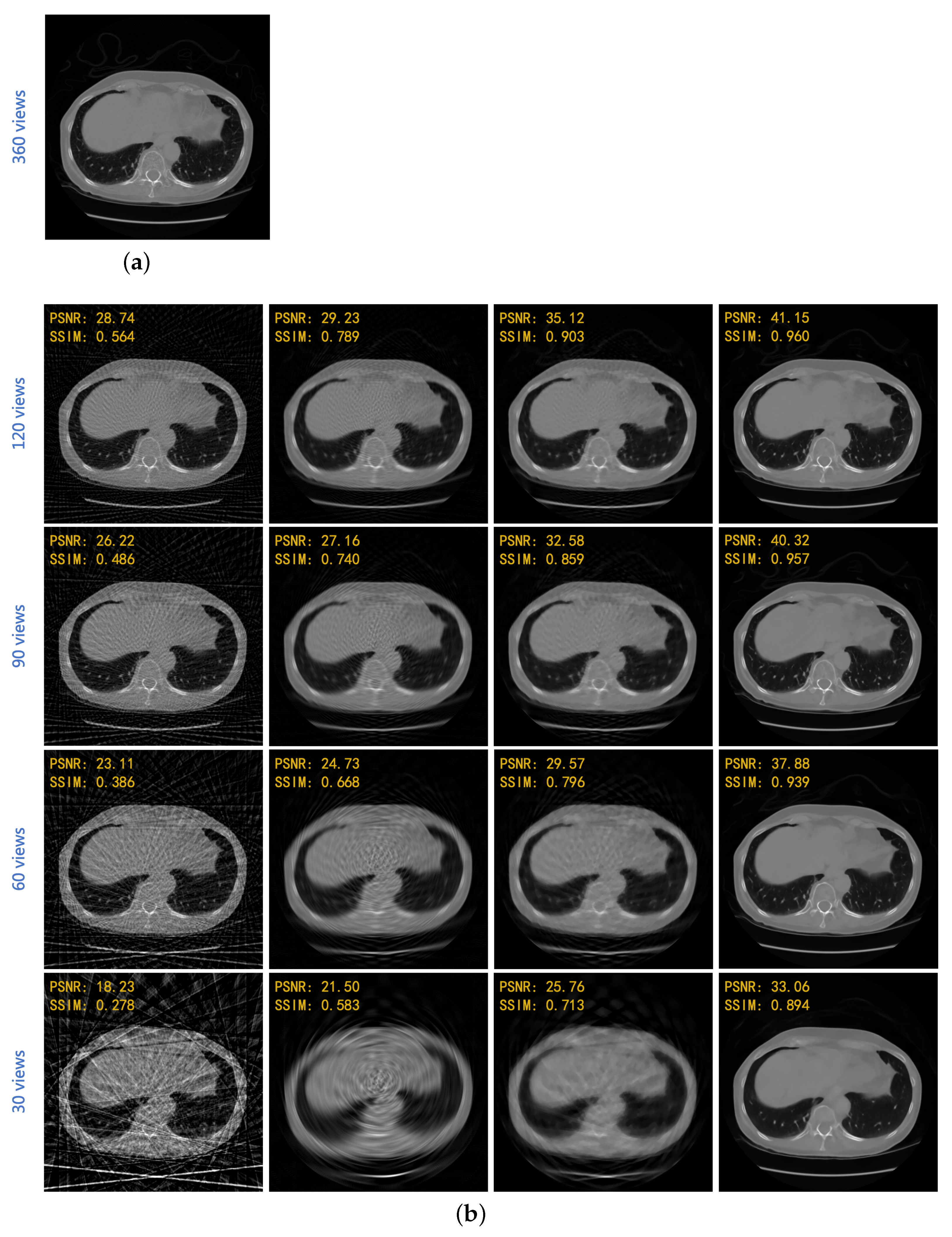
| FBP | Linear + FBP | SART-TV | Proposed | |
|---|---|---|---|---|
| 120 views | 28.725 | 30.241 | 34.405 | 41.049 |
| (3-degree) | 0.558 | 0.802 | 0.903 | 0.958 |
| 90 views | 26.702 | 28.475 | 32.190 | 40.204 |
| (4-degree) | 0.483 | 0.765 | 0.862 | 0.956 |
| 60 views | 23.259 | 26.279 | 30.085 | 37.718 |
| (6-degree) | 0.391 | 0.698 | 0.810 | 0.938 |
| 30 views | 19.496 | 23.399 | 26.711 | 33.100 |
| (12-degree) | 0.280 | 0.624 | 0.726 | 0.891 |
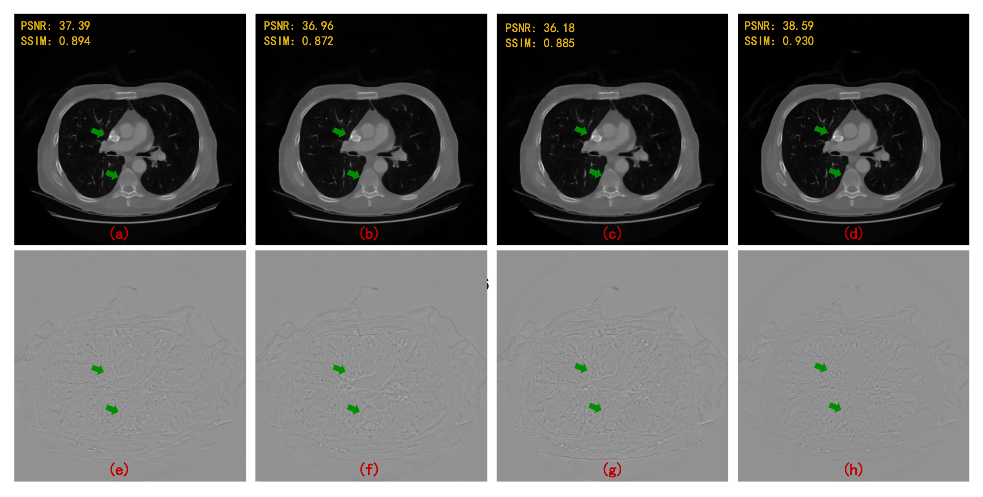
| 90 Views | 60 Views | |||
|---|---|---|---|---|
| PSNR | SSIM | PSNR | SSIM | |
| FBPConvNet [13] | 37.611 | 0.921 | 35.578 | 0.896 |
| RED-CNN [14] | 37.209 | 0.902 | 34.528 | 0.859 |
| DD-Net [22] | 36.380 | 0.912 | 34.424 | 0.892 |
| MWCNN [23] | 38.664 | 0.943 | 36.531 | 0.921 |
| HDNet (WCNN-based) [29] | 34.506 | 0.900 | 32.259 | 0.869 |
| HDNet (Unet-based) [30] | 35.459 | 0.903 | 33.377 | 0.886 |
| HDNet (WUnet-based) | 36.750 | 0.924 | 35.132 | 0.904 |
| HDNet (MWCNN-based) | 40.204 | 0.956 | 37.718 | 0.938 |
Publisher’s Note: MDPI stays neutral with regard to jurisdictional claims in published maps and institutional affiliations. |
© 2022 by the authors. Licensee MDPI, Basel, Switzerland. This article is an open access article distributed under the terms and conditions of the Creative Commons Attribution (CC BY) license (https://creativecommons.org/licenses/by/4.0/).
Share and Cite
Bai, J.; Liu, Y.; Yang, H. Sparse-View CT Reconstruction Based on a Hybrid Domain Model with Multi-Level Wavelet Transform. Sensors 2022, 22, 3228. https://doi.org/10.3390/s22093228
Bai J, Liu Y, Yang H. Sparse-View CT Reconstruction Based on a Hybrid Domain Model with Multi-Level Wavelet Transform. Sensors. 2022; 22(9):3228. https://doi.org/10.3390/s22093228
Chicago/Turabian StyleBai, Jielin, Yitong Liu, and Hongwen Yang. 2022. "Sparse-View CT Reconstruction Based on a Hybrid Domain Model with Multi-Level Wavelet Transform" Sensors 22, no. 9: 3228. https://doi.org/10.3390/s22093228
APA StyleBai, J., Liu, Y., & Yang, H. (2022). Sparse-View CT Reconstruction Based on a Hybrid Domain Model with Multi-Level Wavelet Transform. Sensors, 22(9), 3228. https://doi.org/10.3390/s22093228