
Ground Control System for UAS Safe Landing Area Determination (SLAD) in Urban Air Mobility Operations †


Abstract
:1. Introduction
- Promoting a new installation method for auxiliary equipment (a 2D rotating LiDAR with 3D capabilities, able to provide a point cloud of a volume in the vicinity of the landing site), aimed at improving the autonomous navigation capabilities of a VTOL small UAV (quadcopter, hexacopter, etc.), without installing additional sensors on the aircraft: therefore saving payload mass and power consumption, and enhancing the flight time (endurance).
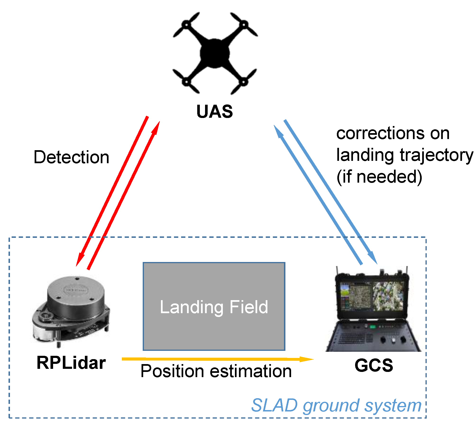
- Proposing the application of safe landing trajectories as a function of the dynamic identification of obstacles in the surveillance volume (humans, hazards, etc.), both in indoor and outdoor scenarios, which is a significant improvement with respect to the ordinary vertical landing path, typical of other onboard autolanding systems. In principle, the LiDAR-equipped ground station could provide safe landing information, even for missions where the UAV is supposed to land on a moving platform. This work presents the design aspects and a validation of the ground system, in terms of providing a point cloud of the 3D surveillance volume (including the landing site), detecting the UAV as it enters the landing volume, estimating its position with respect to the landing site, identifying objects which could impair the safe landing, and monitoring the descent of the flying robot.
- Proposing a ground system capable of providing a safe descent path even in the presence of onboard hardware/software errors (for example, actuator failure, loss of position estimation from a possible IMU embedded in the UAV flight control system, etc.), by providing timely autonomous identification of safe paths, and assisting a controlled descent and land on the ground. Our approach is inspired by typical landing systems for civil aviation, such as ILS (Instrument Landing System) or GCA (Ground Controlled Approach).
- Proposing a simple and cost-effective alternative to vision-based SLAD methods.
- Developing a simple, cheap and useful obstacle detection system by analyzing the point cloud characteristics obtained by the ground-based LiDAR, with a clustering algorithm based on difference “images” of two corrected point cloud scenarios, with and without the obstacle.
- Promoting a methodology of safe landing area determination in GPS-denied environments, in failure scenarios, or when the aircraft is not equipped with a precise localization system, therefore extending the application domain of UAVs/UASs, especially multirotor helicopters.
- Proposing a potential minimum landing time approach for small, fast-moving small/micro UAVs in a variety of environments (typical flight speed of 10 m/s and 30 min battery life).
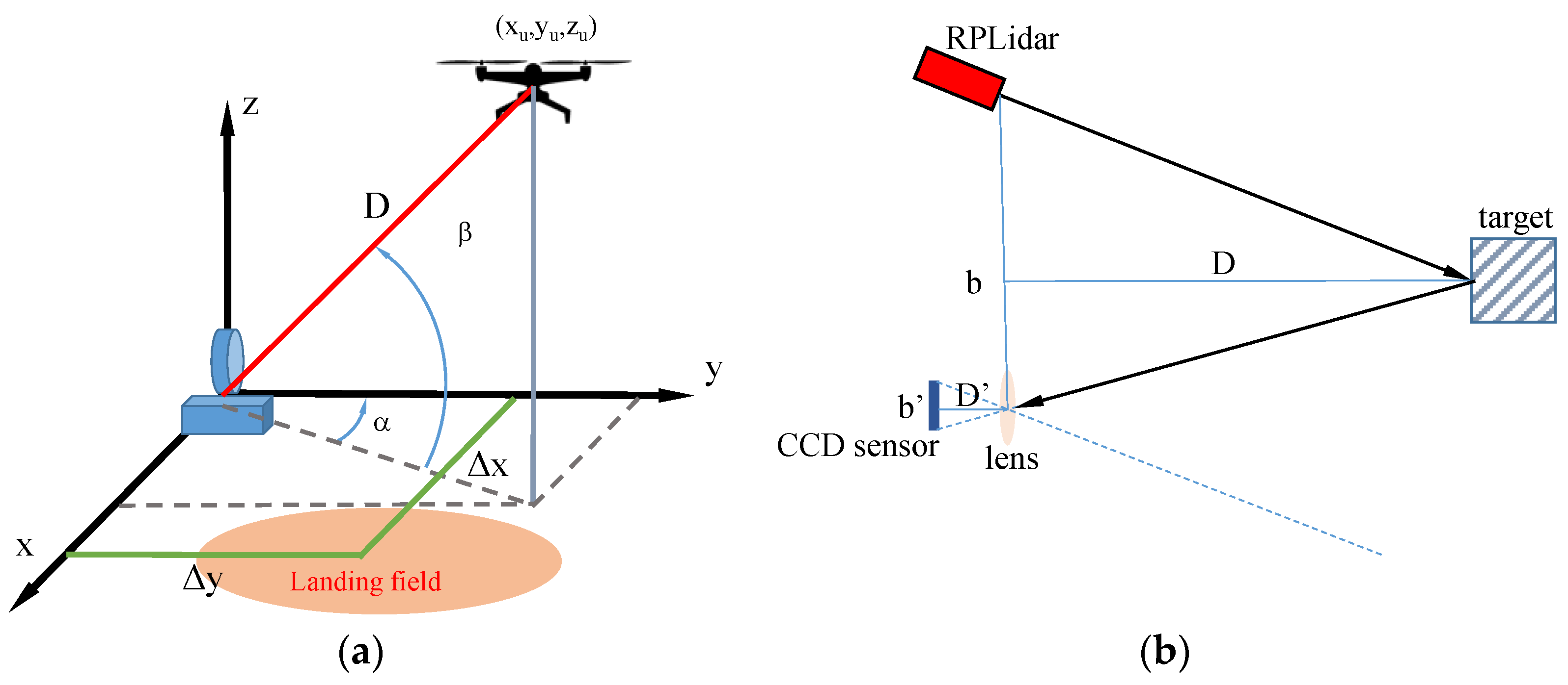
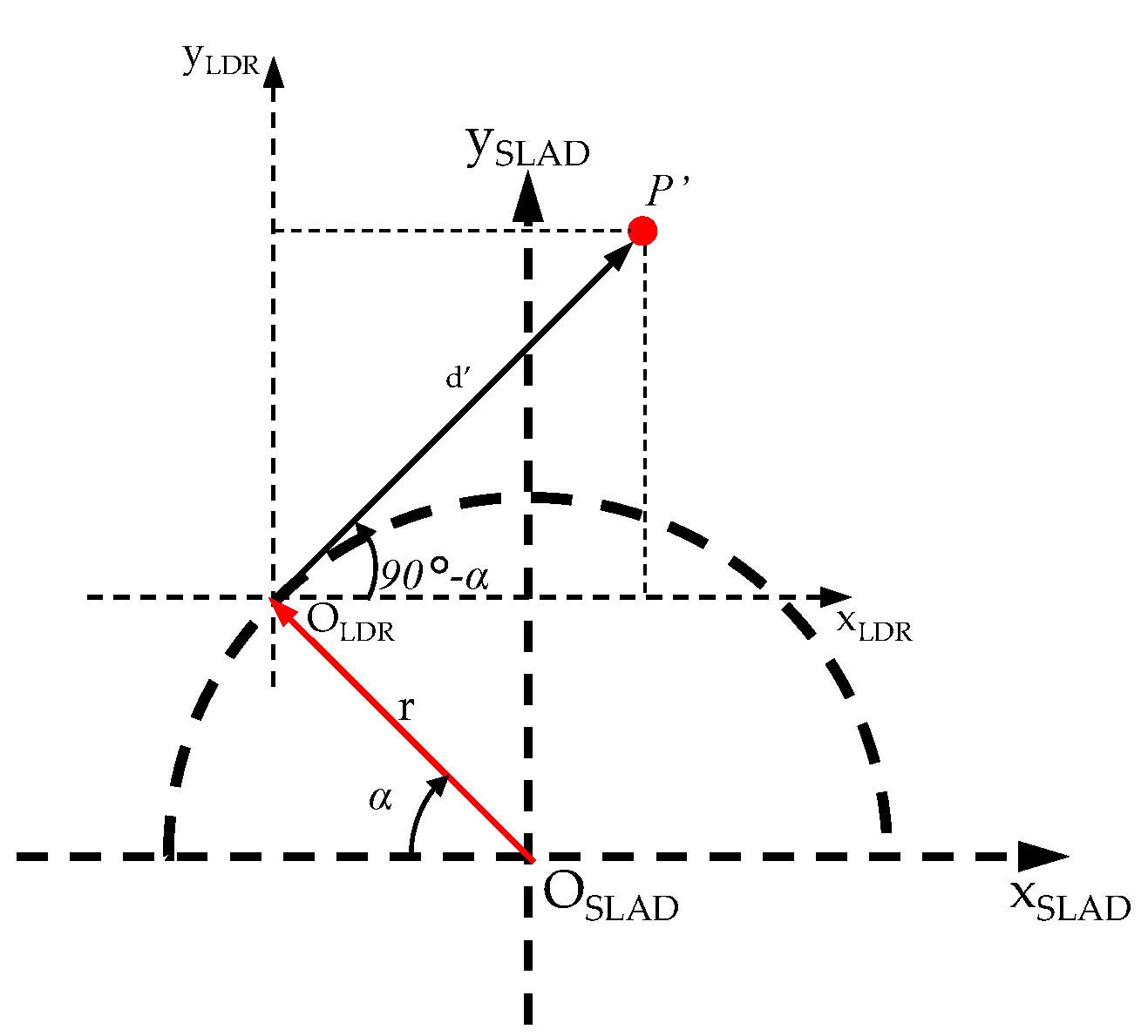
2. Theoretical Framework
3. SLAD Ground System
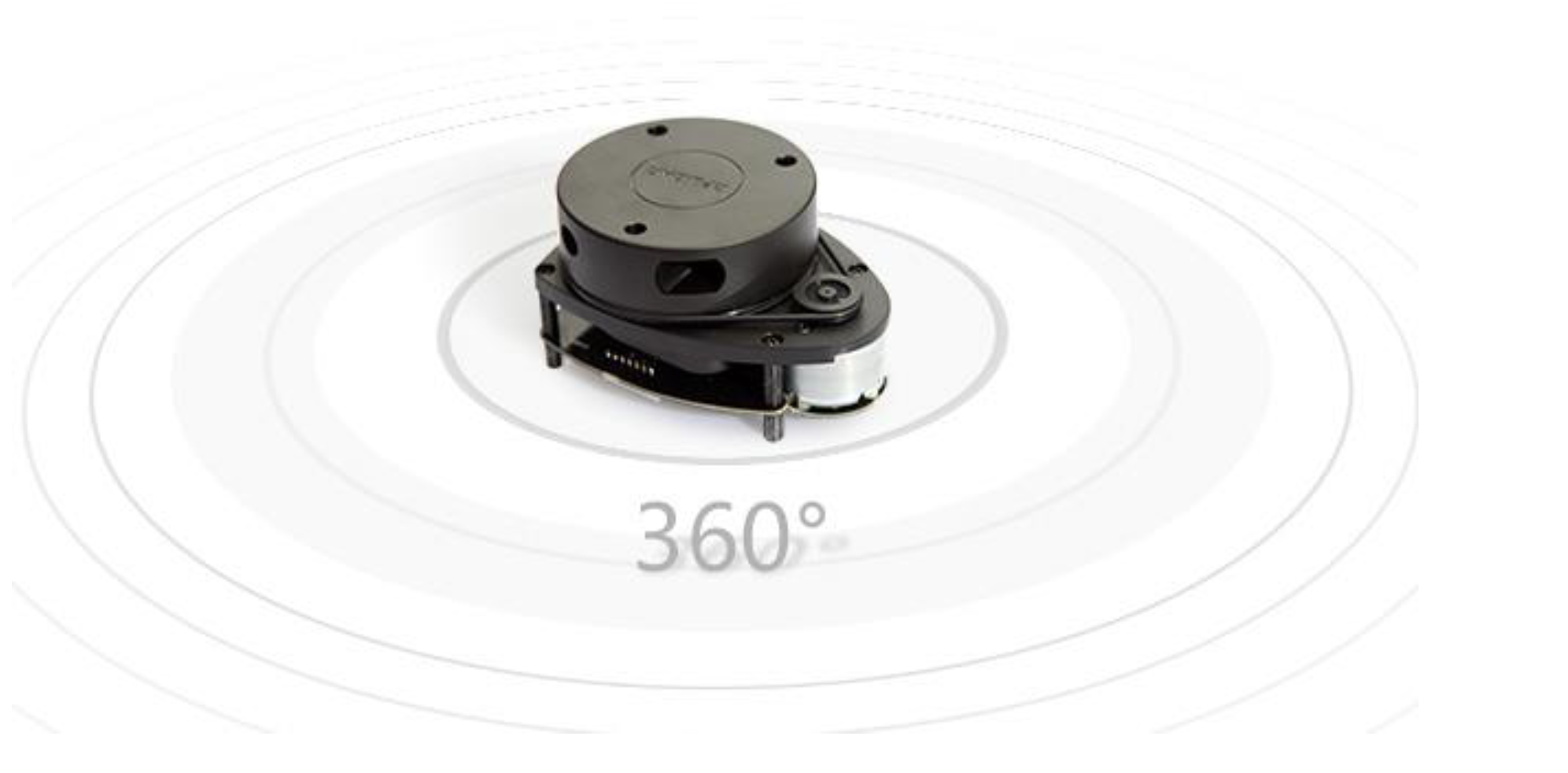
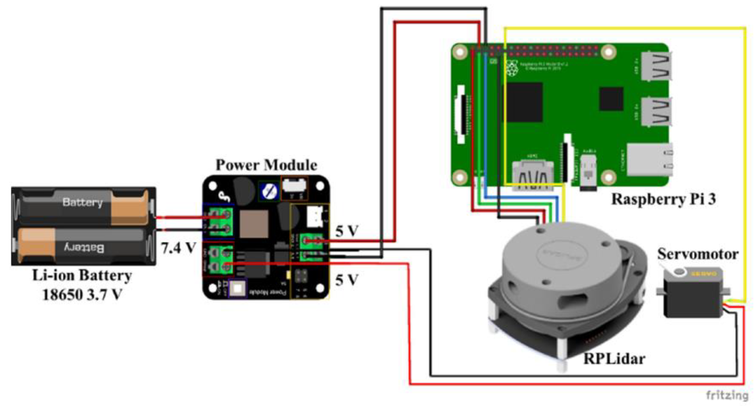
- − RPLiDAR sensor, model A1M8;
- − Raspberry Pi 3 (SBC);
- − 5-A Power Module;
- − Servo motor with standing structure;
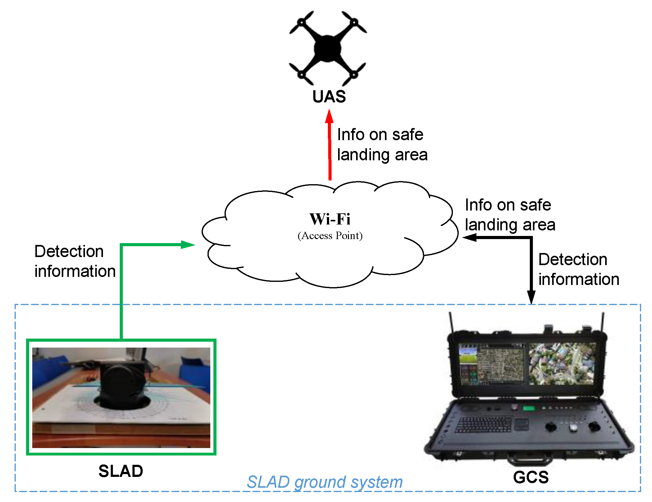
- − PC-based Ground Control Station to manage LiDAR data and send clearance data (safe paths, safe landing zone) to the UAV;
- − Communication subsystem for real-time data transfer from the sensor to the GCS and transmission of safety information to the UAV.
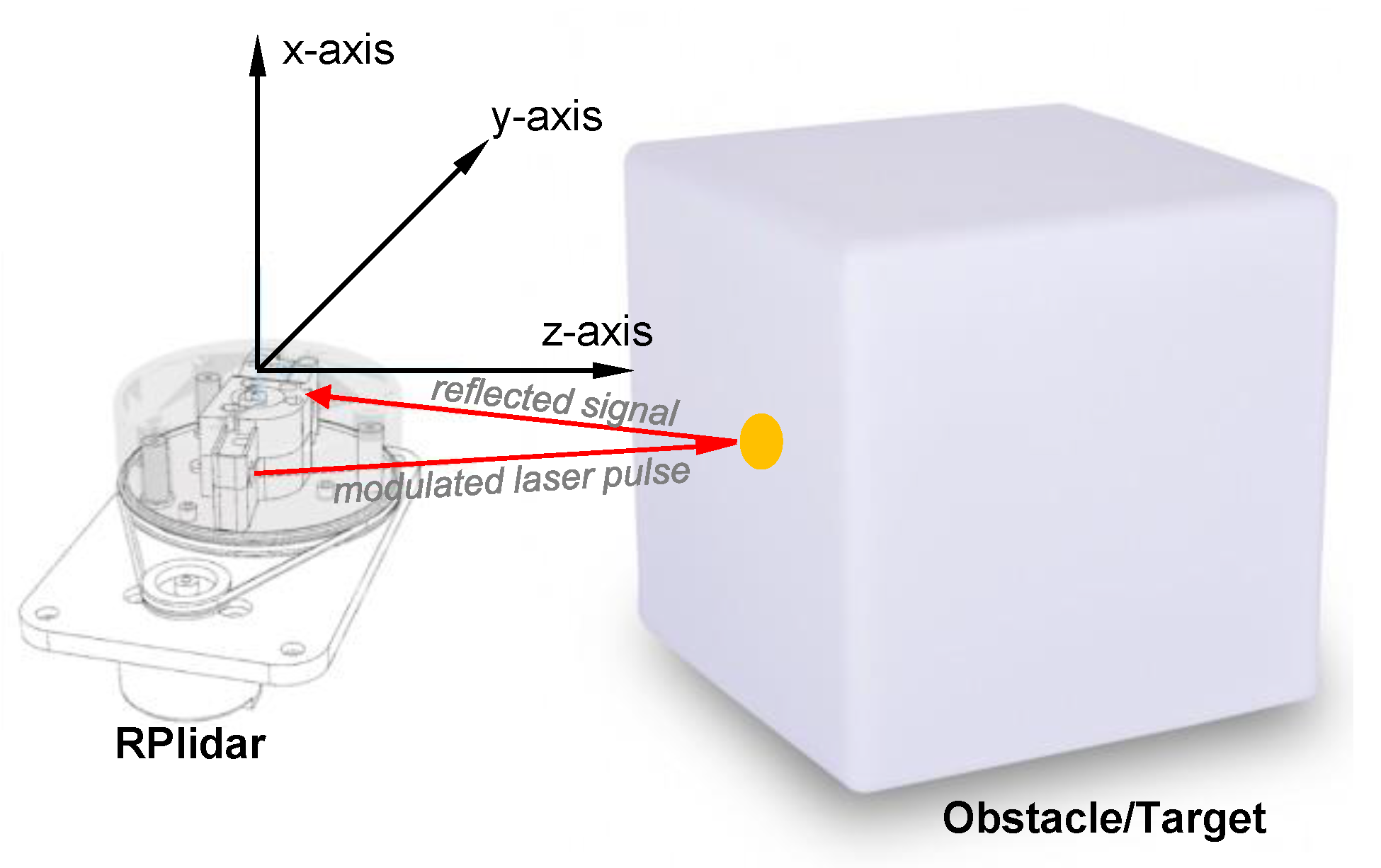
3.1. LiDAR Sensor: RPLIDAR Model A1M8
3.2. Raspberry PI 3
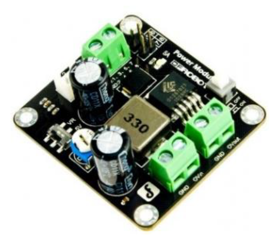
3.3. Power Module
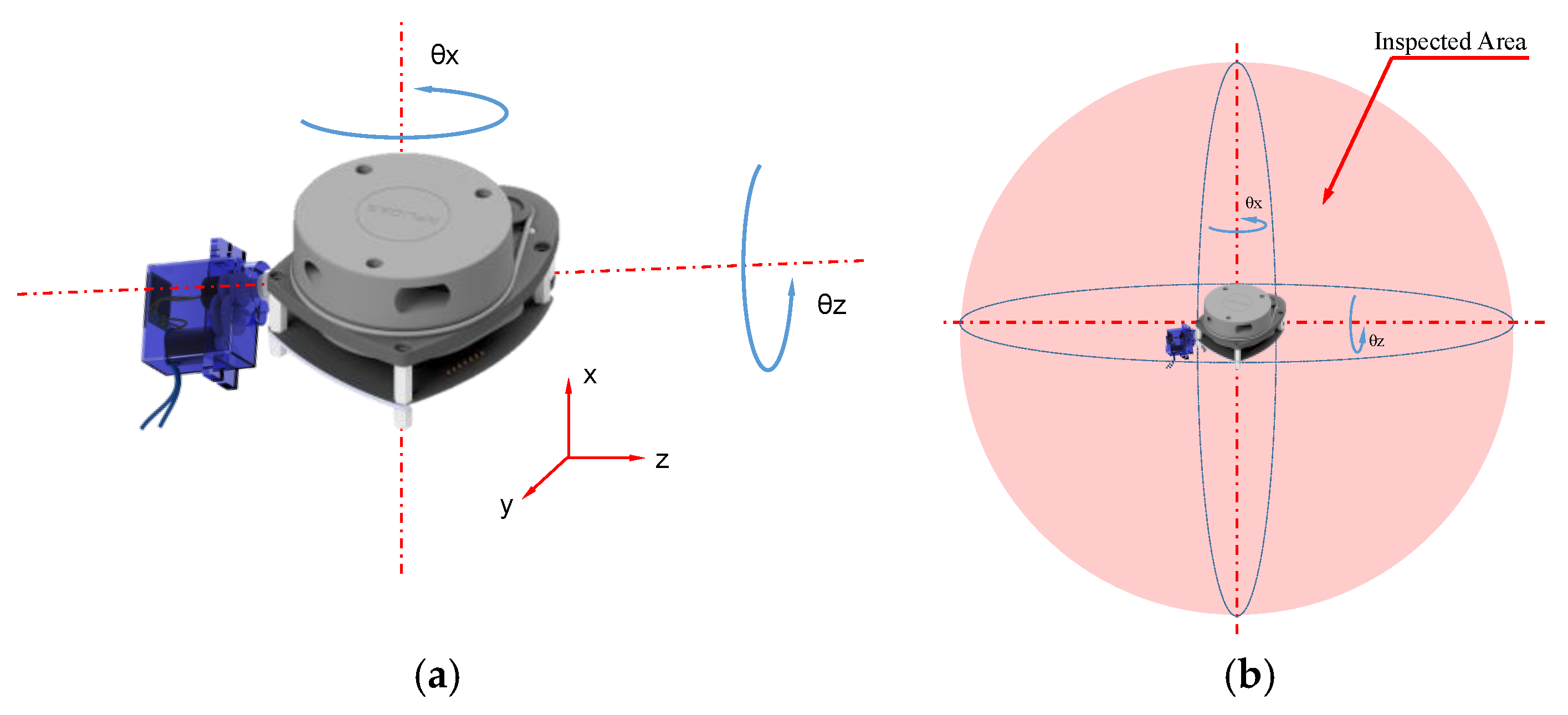
3.4. Standing SLAD Structure
3.5. Communication Subsystem
4. Experimental Tests and Results
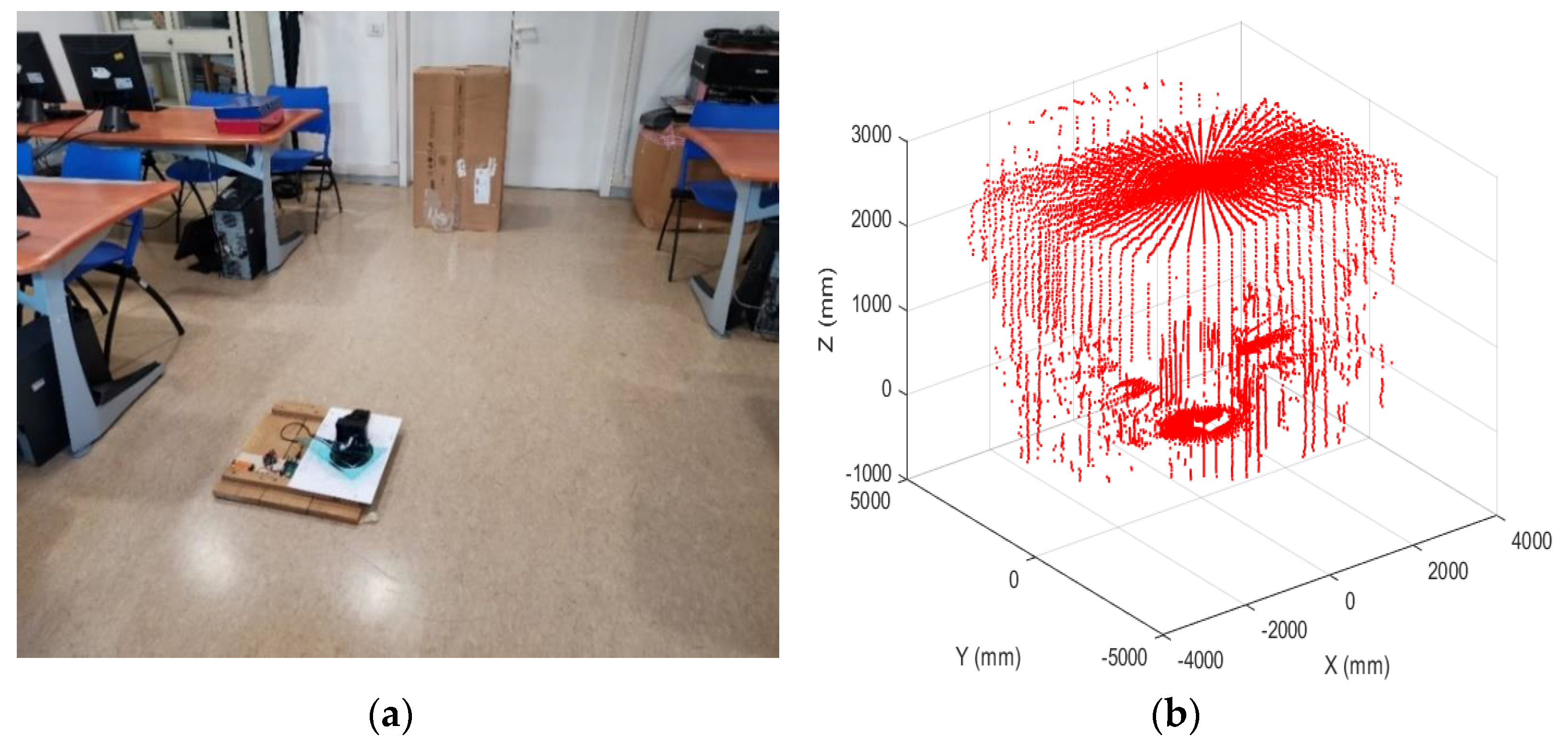
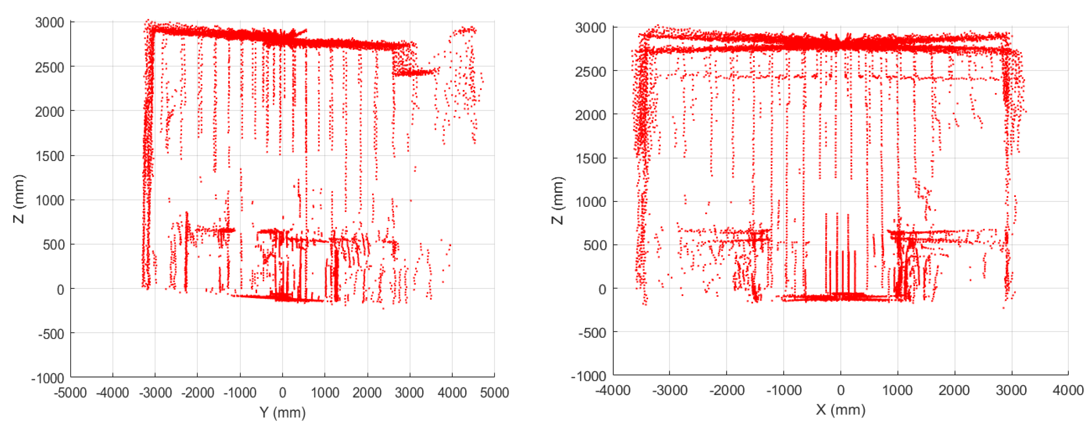
4.1. Validation of Laboratory Tests
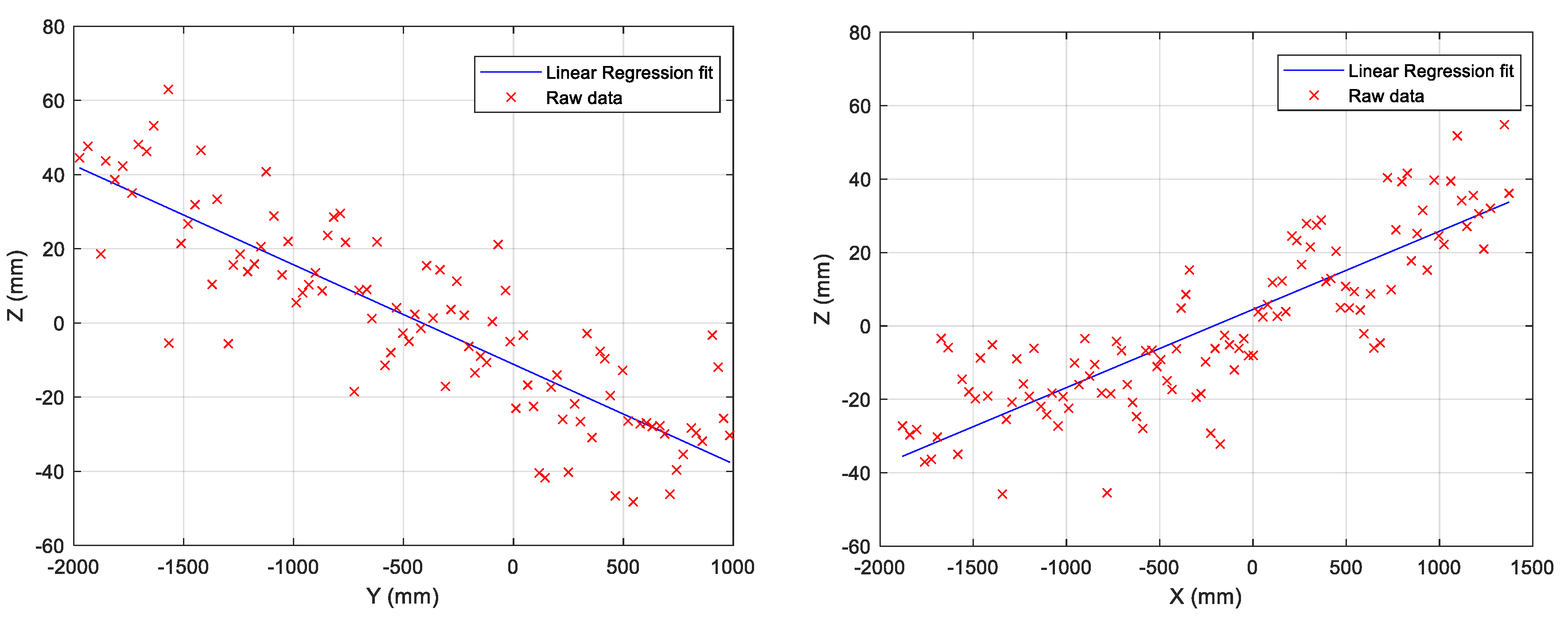
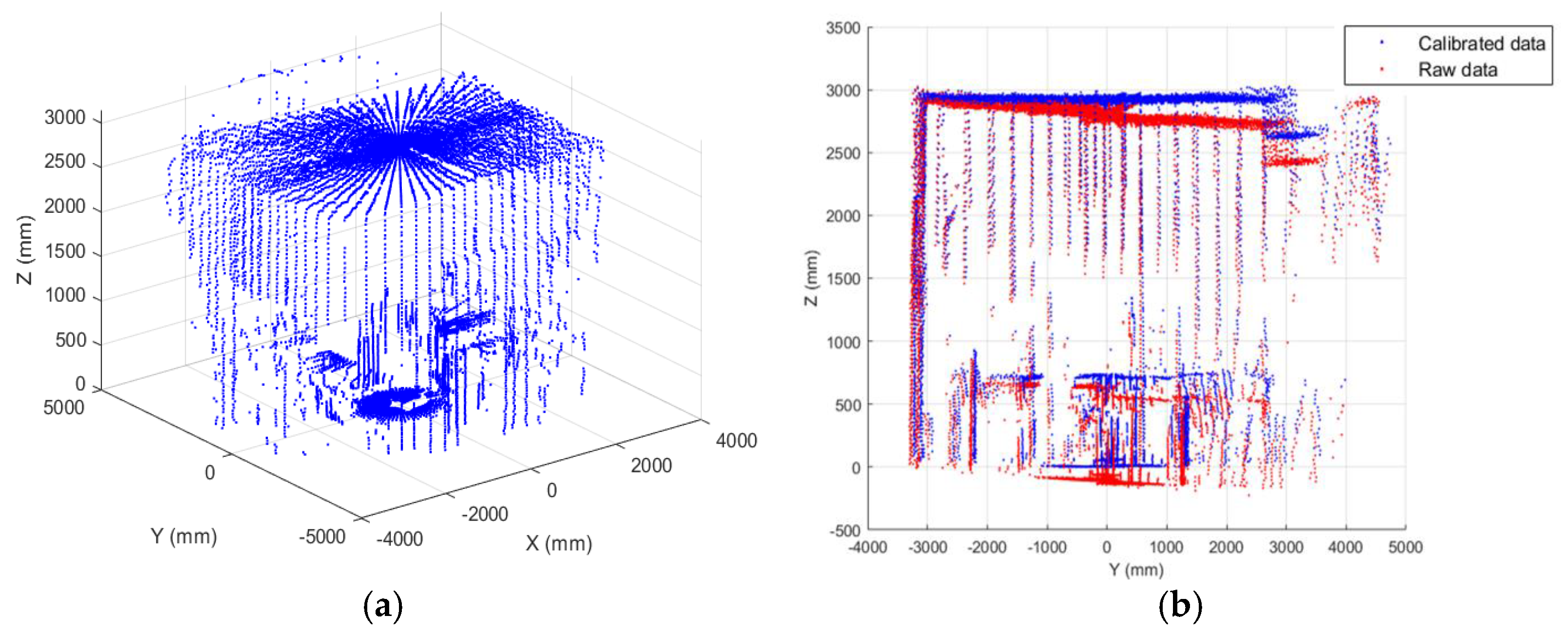
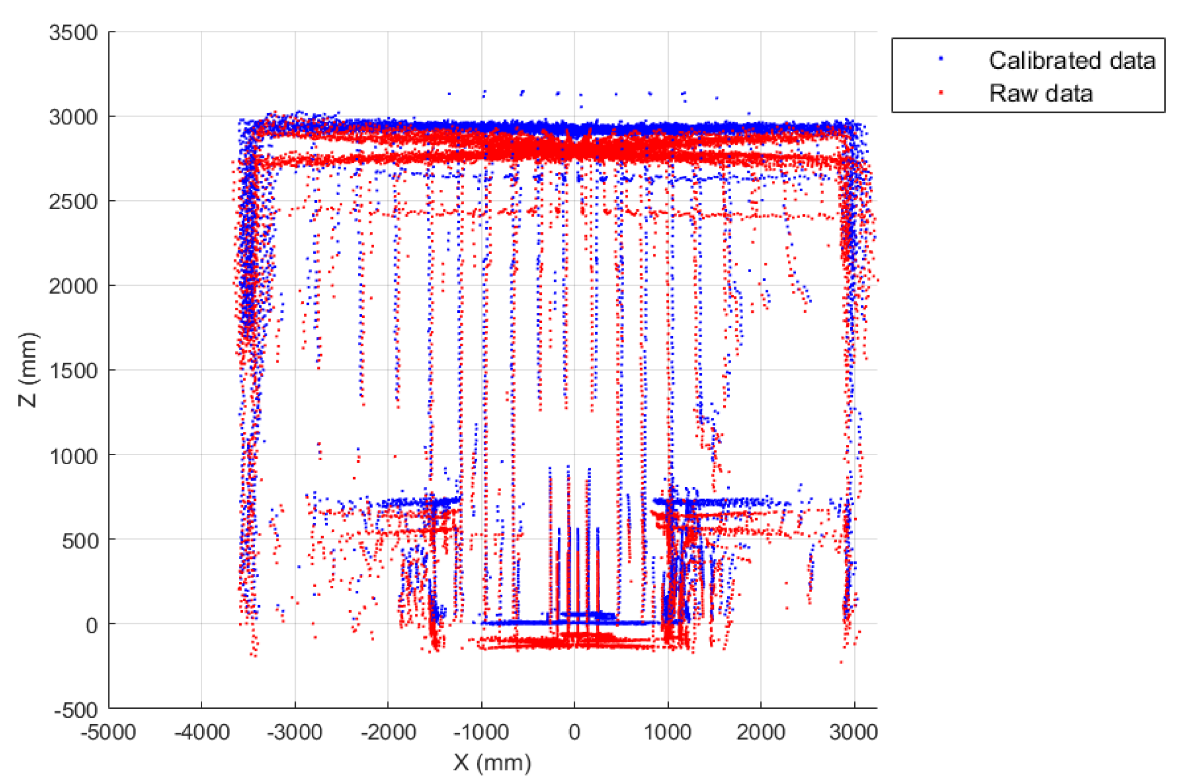
4.2. SLAD System Extrinsic Calibration: Removal of Disalignment and Nonlinear Distortions
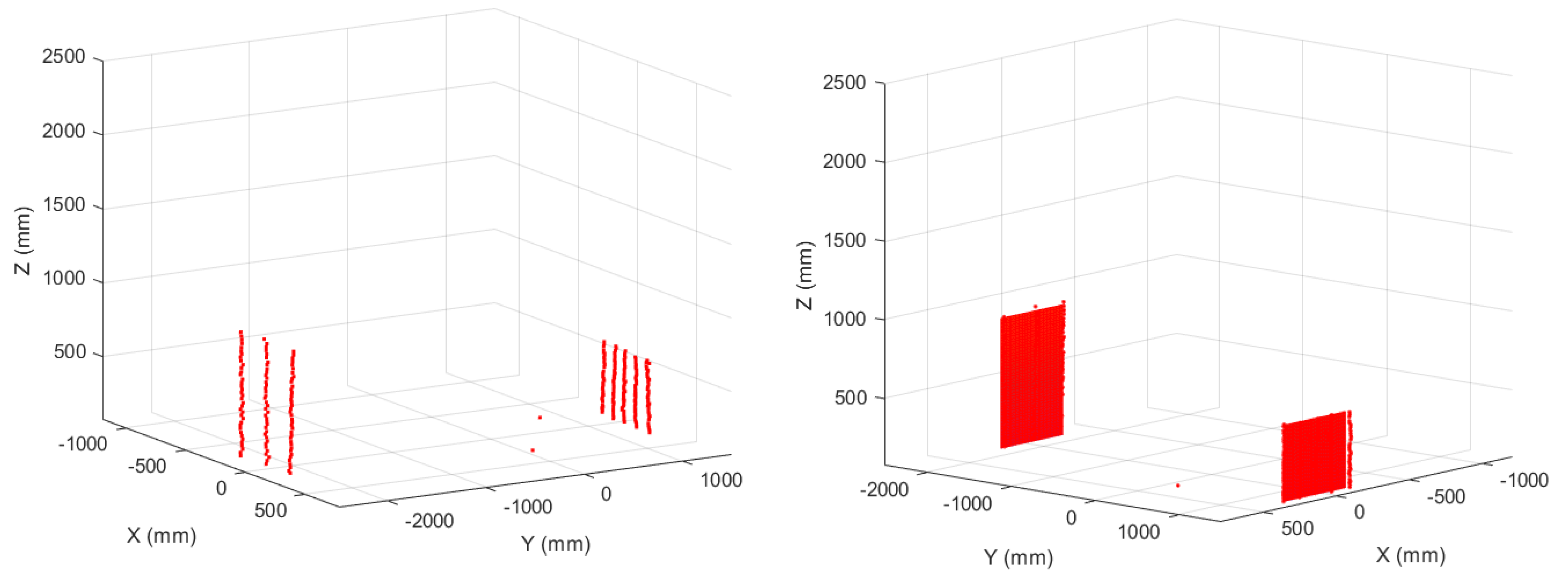
4.3. Obstacle Detection Methodology
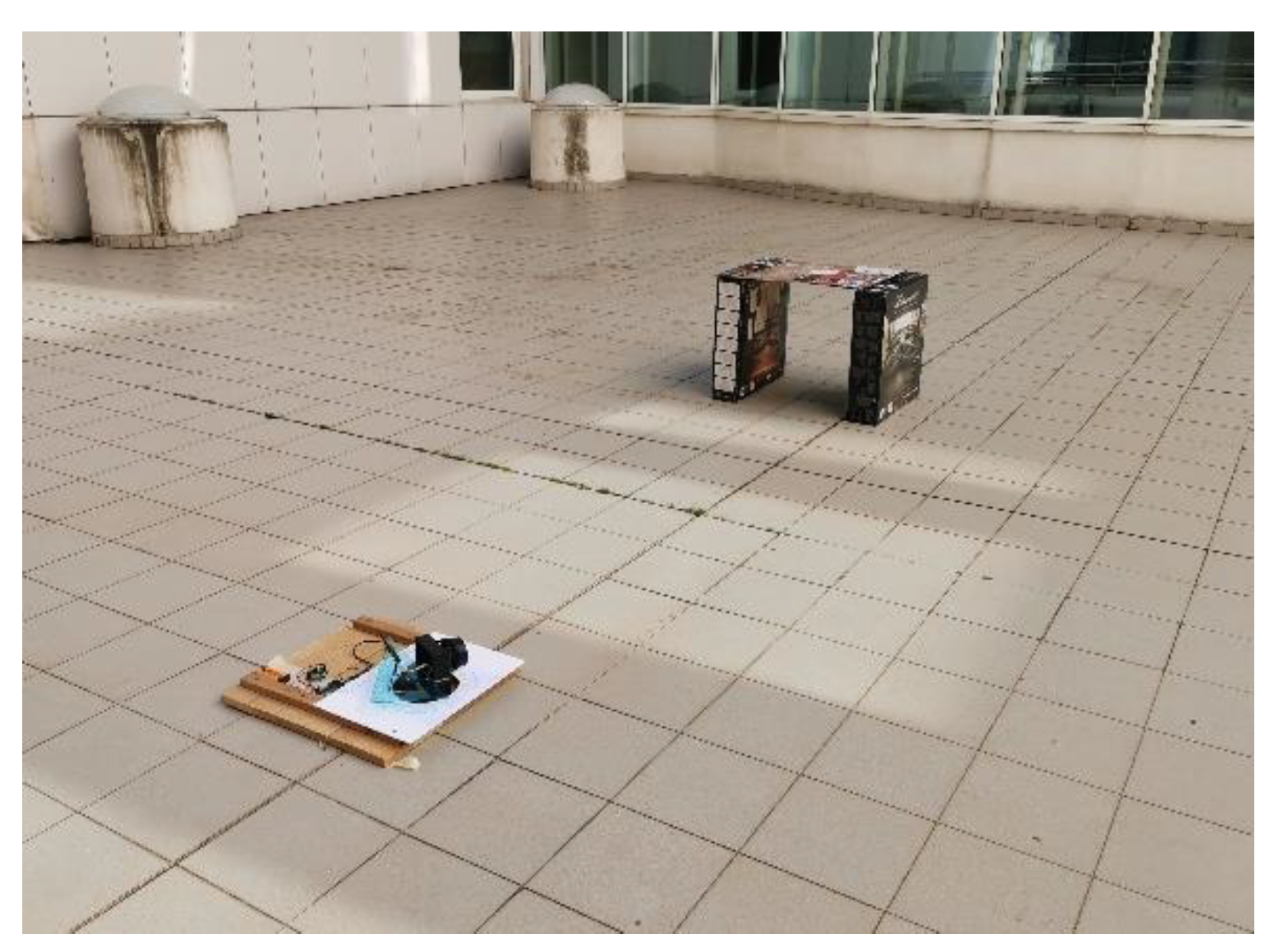
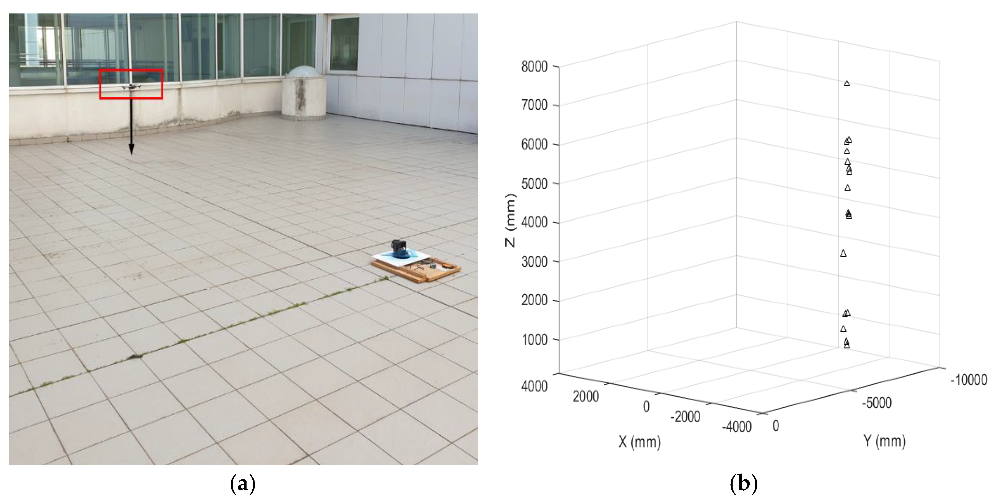
4.4. Outdoor Validation Test
5. Conclusions and Further Work
Author Contributions
Funding
Informed Consent Statement
Conflicts of Interest
References
- Valavanis, K.P.; Vachtsevanos, G.J. (Eds.) Handbook of Unmanned Aerial Vehicles; Springer Reference: Cham, Switzerland, 2015. [Google Scholar]
- Austin, R. Unmanned Aircraft Systems; Wiley: Hoboken, NJ, USA, 2010. [Google Scholar]
- Papa, U. Embedded Platforms for UAS Landing Path and Obstacle Detection. In Studies in Systems, Decision and Control; Springer: Cham, Switzerland, 2018; Volume 136. [Google Scholar]
- Wargo, C.A.; Church, G.C.; Glaneueski, J.; Strout, M. Unmanned Aircraft Systems (UAS) research and future analysis. In Proceedings of the 2014 IEEE Aerospace Conference, Big Sky, MT, USA, 1–8 March 2014; pp. 1–16. [Google Scholar]
- Gupta, S.G.; Ghonge, M.M.; Jawandhiya, P.M. Review of unmanned aircraft system (UAS). Int. J. Adv. Res. Comput. Eng. Technol. 2013, 2, 1646–1658. [Google Scholar] [CrossRef]
- SESAR Joint Undertaking. European Drones Outlook Study—Technical Report; European Commission: Brussels, Belgium, 2016. [Google Scholar]
- Finn, R.L.; Wright, D. Unmanned aircraft systems: Surveillance, ethics and privacy in civil applications. Comput. Law Secur. Rev. 2012, 28, 184–194. [Google Scholar] [CrossRef]
- NATO Standardization Agency. NATO STANAG 4670 (Edition 1) Recommended Guidance for the Training of Designated Unmanned Aerial Vehicle Operator (DUO). 2006. [Google Scholar]
- NATO Standardization Agency. NATO STANAG 4670—ATP-3.3.7, (Edition 3) Guidance for the Training of Unmanned Aircraft Systems (UAS) Operators. 2014. Available online: http://everyspec.com/NATO/NATO-STANAG/SRANAG-4670_ED-3_52054/ (accessed on 4 January 2022).
- Chapman, A.; Mesbahi, M. UAV Swarms: Models and Effective Interfaces. In Handbook of Unmanned Aerial Vehicles; Valavanis, K.P., Vachtsevanos, G.J., Eds.; Springer Reference: Cham, Switzerland, 2015; pp. 1987–2019. [Google Scholar]
- Thipphavong, D.P.; Apaza, R.; Barmore, B.; Battiste, V.; Burian, B.; Dao, Q.; Verma, S.A. Urban air mobility air-space integration concepts and considerations. In Proceedings of the 2018 Aviation Technology, Integration, and Operations Conference, Atlanta, GA, USA, June 25–29 2018; p. 3676. [Google Scholar]
- Hasan, S. Urban Air Mobility (UAM) Market Study. 2018; p. 148. Available online: https://ntrs.nasa.gov/citations/20190026762 (accessed on 4 January 2022).
- Cotton, W.B.; Wing, D.J. Airborne trajectory management for urban air mobility. In Proceedings of the 2018 Aviation Technology, Integration, and Operations Conference, Atlanta, GA, USA, June 25–29 2018; p. 3674. [Google Scholar] [CrossRef] [Green Version]
- European Union Aviation Safety Agency (EASA). Easy Access Ruler for Unmanned Aircraft Systems; © European Union: Brussels, Belgium, 2021; p. 308. [Google Scholar]
- Gautam, A.; Sujit, P.B.; Saripalli, S. A survey of autonomous landing techniques for UAVs. In Proceedings of the 2014 International Conference on Unmanned Aircraft Systems (ICUAS), Orlando, FL, USA, 27–30 May 2014; pp. 1210–1218. [Google Scholar]
- Ariante, G.; Papa, U.; Ponte, S.; Del Core, G. UAS for positioning and field mapping using LiDAR and IMU sensors data: Kalman filtering and integration. In Proceedings of the 2019 IEEE 5th International Workshop on Metrology for AeroSpace (MetroAeroSpace), Turin, Italy, 19–21 June 2019; pp. 522–527. [Google Scholar]
- Ponte, S.; Ariante, G.; Papa, U.; Del Del Core, G. An Embedded Platform for Positioning and Obstacle Detection for Small Unmanned Aerial Vehicles. Electronics 2020, 9, 1175. [Google Scholar] [CrossRef]
- Ariante, G. Embedded System for Precision Positioning, Detection, and Avoidance (PODA) for Small UAS. IEEE Aerosp. Electron. Syst. Mag. 2020, 35, 38–42. [Google Scholar] [CrossRef]
- Papa, U.; Ariante, G.; Del Core, G. UAS aided landing and obstacle detection through LIDAR-sonar data. In Proceedings of the 2018 5th IEEE International Workshop on Metrology for AeroSpace (MetroAeroSpace), Rome, Italy, 20–22 June 2018; pp. 478–483. [Google Scholar]
- Bijjahalli, S.; Sabatini, R.; Gardi, A. GNSS Performance Modelling and Augmentation for Urban Air Mobility. Sensors 2019, 19, 4209. [Google Scholar] [CrossRef] [Green Version]
- Patterson, T.; McClean, S.; Morrow, P.; Parr, G.; Luo, C. Timely autonomous identification of UAV safe landing zones. Image Vis. Comput. 2014, 32, 568–578. [Google Scholar] [CrossRef]
- Shen, Y.-F.; Rahman, Z.; Krusienski, D.; Li, J. A Vision-Based Automatic Safe Landing-Site Detection System. IEEE Trans. Aerosp. Electron. Syst. 2013, 49, 294–311. [Google Scholar] [CrossRef]
- Kaljahi, M.A.; Shivakumara, P.; Idris, M.Y.I.; Anisi, M.H.; Lu, T.; Blumenstein, M.; Noor, N.M. An automatic zone detection system for safe landing of UAVs. Expert Syst. Appl. 2019, 122, 319–333. [Google Scholar] [CrossRef] [Green Version]
- Bosch, S.; Lacroix, S.; Caballero, F. Autonomous detection of safe landing areas for an UAV from monocular images. In Proceedings of the 2006 IEEE/RSJ International Conference on Intelligent Robots and Systems, Beijing, China, 9–15 October 2006; pp. 5522–5527. [Google Scholar]
- Mukadam, K.; Sinh, A.; Karani, R. Detection of landing areas for unmanned aerial vehicles. In Proceedings of the 2016 International Conference on Computing Communication Control and automation (ICCUBEA), Pune, India, 12–13 August 2016; pp. 1–5. [Google Scholar]
- Patterson, T.; McClean, S.; Morrow, P.; Parr, G. Modeling safe landing zone detection options to assist in safety critical UAV decision making. Procedia Comput. Sci. 2012, 10, 1146–1151. [Google Scholar] [CrossRef] [Green Version]
- Cesetti, A.; Frontoni, E.; Mancini, A.; Zingaretti, P.; Longhi, S. A Vision-Based Guidance System for UAV Navigation and Safe Landing using Natural Landmarks. J. Intell. Robot. Syst. 2009, 57, 233–257. [Google Scholar] [CrossRef]
- Yang, T.; Li, P.; Zhang, H.; Li, J.; Li, Z. Monocular Vision SLAM-Based UAV Autonomous Landing in Emergencies and Unknown Environments. Electronics 2018, 7, 73. [Google Scholar] [CrossRef] [Green Version]
- Yan, L.; Qi, J.; Wang, M.; Wu, C.; Xin, J. A Safe Landing Site Selection Method of UAVs Based on LiDAR Point Clouds. In Proceedings of the 2020 39th Chinese Control Conference (CCC), Shenyang, China, 27–29 July 2020; pp. 6497–6502. [Google Scholar]
- Shin, Y.H.; Lee, S.; Seo, J. Autonomous safe landing-area determination for rotorcraft UAVs using multiple IR-UWB radars. Aerosp. Sci. Technol. 2017, 69, 617–624. [Google Scholar] [CrossRef]
- Allignol, C.; Barnier, N.; Durand, N.; Blond, E. Detect and Avoid, UAV integration in the lower airspace Traffic. In Proceedings of the 7th International Conference on Research on Air Transportation (ICRAT 2016), Philadelphia, PA, USA, 15–18 June 2016; Available online: https://hal.archives-ouvertes.fr/hal-03165027 (accessed on 10 January 2022).
- Hoffmann, F.; Ritchie, M.; Fioranelli, F.; Charlish, A.; Griffiths, H. Micro-Doppler based detection and tracking of UAVs with multistatic radar. In Proceedings of the 2016 IEEE Radar Conference (RadarConf), Philadelphia, PA, USA, 1–6 May 2016; pp. 1–6. [Google Scholar]
- Blažic, A.; Kotnik, K.; Nikolovska, K.; Ožbot, M.; Pernuš, M.; Petkovic, U.; Hrušovar, N.; Verbic, M.; Ograjenšek, I.; Zdešar, A.; et al. Autonomous Landing System: Safe Landing Zone Identification. SNE Simul. Notes Eur. 2018, 28, 165–170. [Google Scholar] [CrossRef]
- Royo, S.; Ballesta-Garcia, M. An Overview of Lidar Imaging Systems for Autonomous Vehicles. Appl. Sci. 2019, 9, 4093. [Google Scholar] [CrossRef] [Green Version]
- Ariante, G.; Ponte, S.; Papa, U.; Del Core, G. Safe Landing Area Determination (SLAD) for Unmanned Aircraft Systems by using rotary LiDAR. In Proceedings of the 2021 IEEE 8th International Workshop on Metrology for AeroSpace (Metro-AeroSpace), Naples, Italy, 23–25 June 2021; pp. 110–115. [Google Scholar]
- Shangai Slamtec Co., Ltd. RPLIDAR A1. Introduction and Datasheet (Model: A1M8), Rev. 1.0. 2016. Available online: https://www.generationrobots.com/media/rplidar-a1m8-360-degree-laser-scanner-development-kit-datasheet-1.pdf (accessed on 24 January 2022).
- Debeunne, C.; Vivet, D. A Review of Visual-LiDAR Fusion based Simultaneous Localization and Mapping. Sensors 2020, 20, 2068. [Google Scholar] [CrossRef] [PubMed] [Green Version]
- Shangai Slamtec Co. RPLIDAR A1. Development Kit User Manual. Rev. 1.0. 2016. Available online: http://www.dfrobot.com/image/data/DFR0315/rplidar_devkit_manual_en.pdf (accessed on 24 January 2022).
- Raspberry Pi (Trading), Ltd. Raspberry Pi Compute Module 3+. Release 1, January 2019. Available online: https://www.raspberrypi (accessed on 10 January 2022).
- DF Robot. Power Module 5A DFRobot 25 W. 2016. Available online: https://wiki.dfrobot.com/Power_Module_SKU_DFR0205_ (accessed on 10 January 2022).
- Ylonen, T. The Secure Shell (SSH) Protocol Architecture. Network Working Group, Cisco Systems, Inc. 2006. Available online: https://datatracker.ietf.org/doc/html/rfc4251 (accessed on 10 January 2022).
- Robert Bosch Power Tools GmbH. PLR 30 C/PLR 40 C Manual. 2019. Available online: https://www.libble.eu/bosch-plr-40-c/online-manual-894647/ (accessed on 24 January 2022).
- Xu, J.; Lv, J.; Pan, Z.; Liu, Y.; Chen, Y. Real-Time LiDAR Data Assocation Aided by IMU in High Dynamic Environment. In Proceedings of the 2018 IEEE International Conference on Real-Time Computing and Robotics (RCAR), Kandima, Maldives, 1–5 August 2018; pp. 202–205. [Google Scholar] [CrossRef]
- Rozsa, Z.; Sziranyi, T. Obstacle Prediction for Automated Guided Vehicles Based on Point Clouds Measured by a Tilted LIDAR Sensor. IEEE Trans. Intell. Transp. Syst. 2018, 19, 2708–2720. [Google Scholar] [CrossRef] [Green Version]
- Zheng, L.; Zhang, P.; Tan, J.; Li, F. The Obstacle Detection Method of UAV Based on 2D Lidar. IEEE Access 2019, 7, 163437–163448. [Google Scholar] [CrossRef]
- Li, B. 3D fully convolutional network for vehicle detection in point cloud. In Proceedings of the 2017 IEEE/RSJ International Conference on Intelligent Robots and Systems (IROS), Vancouver, BC, Canada, 24–28 September 2017; pp. 1513–1518. [Google Scholar] [CrossRef] [Green Version]
- Hammer, M.; Hebel, M.; Laurenzis, M.; Arens, M. Lidar-based detection and tracking of small UAVs. In Proceedings of the SPIE 10799, Emerging Imaging and Sensing Technologies for Security and Defence III; and Unmanned Sensors, Systems, and Countermeasures, Berlin, Germany, 12 September 2018. [Google Scholar] [CrossRef]


| Class | Category | Normal Employment | Normal Operating Altitude | Normal Operating Radius | Primary Supported Commander | Example Platform |
|---|---|---|---|---|---|---|
| III (>600 kg) | Strike/combat | Strategic/National | up to 65,000 ft | Unlimited (BLOS) | Theatre | Reaper |
| HALE (High Altitude, Long Endurance) | Strategic/National | up to 65,000 ft | Unlimited (BLOS) | Theatre | Global Hawk | |
| MALE (Medium Altitude, Long Endurance) | Operational/Theatre | up to 45,000 ft | Unlimited (BLOS) | JTF | Heron | |
| II (150 kg–600 kg) | Tactical | Tactical Formation | up to 18,000 ft AGL | 200 km (LOS) | Brigade | Hermes 450 |
| I (<150 kg) | Small (>15 kg) | Tactical Unit | up to 5000 ft AGL | 50 km (LOS) | Battalion, Regiment | Scan Eagle |
| Mini (<15 kg) | Tactical Subunit (manual or hand launch) | up to 3000 ft AGL | Up to 25 km (LOS) | Company, Platoon, Squad | Skylark | |
| Micro 1 (<66 J) | Tactical Subunit (manual or hand launch) | up to 200 ft AGL | Up to 5 km (LOS) | Platoon, Squad | Black Widow |
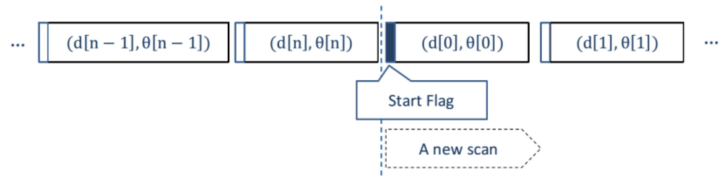
| Data Type | Unit | Description |
|---|---|---|
| Distance, d | mm | Current measured distance value |
| Heading, θ | degrees | Current heading angle of the measurement |
| Quality | level | Quality of the measurement |
| Start Flag | (Boolean) | Flag of a new scan |
| Axis | m | q |
|---|---|---|
| Y-Z | −0.021 | 2796 |
| X-Z | 0.020 | 2799 |
| Angle | Value (deg) |
|---|---|
| Φ | −1.23 |
| Θ | 1.15 |
| Angle | Value (deg) |
|---|---|
| Φ | 1.02 |
| Θ | 1.08 |
Publisher’s Note: MDPI stays neutral with regard to jurisdictional claims in published maps and institutional affiliations. |
© 2022 by the authors. Licensee MDPI, Basel, Switzerland. This article is an open access article distributed under the terms and conditions of the Creative Commons Attribution (CC BY) license (https://creativecommons.org/licenses/by/4.0/).
Share and Cite
Ariante, G.; Ponte, S.; Papa, U.; Greco, A.; Del Core, G. Ground Control System for UAS Safe Landing Area Determination (SLAD) in Urban Air Mobility Operations. Sensors 2022, 22, 3226. https://doi.org/10.3390/s22093226
Ariante G, Ponte S, Papa U, Greco A, Del Core G. Ground Control System for UAS Safe Landing Area Determination (SLAD) in Urban Air Mobility Operations. Sensors. 2022; 22(9):3226. https://doi.org/10.3390/s22093226
Chicago/Turabian StyleAriante, Gennaro, Salvatore Ponte, Umberto Papa, Alberto Greco, and Giuseppe Del Core. 2022. "Ground Control System for UAS Safe Landing Area Determination (SLAD) in Urban Air Mobility Operations" Sensors 22, no. 9: 3226. https://doi.org/10.3390/s22093226
APA StyleAriante, G., Ponte, S., Papa, U., Greco, A., & Del Core, G. (2022). Ground Control System for UAS Safe Landing Area Determination (SLAD) in Urban Air Mobility Operations. Sensors, 22(9), 3226. https://doi.org/10.3390/s22093226