
Guidelines for Installation of Sensors in Smart Sensing Platforms in Underground Spaces


Abstract
1. Introduction
2. Theoretical Concept and Methodology
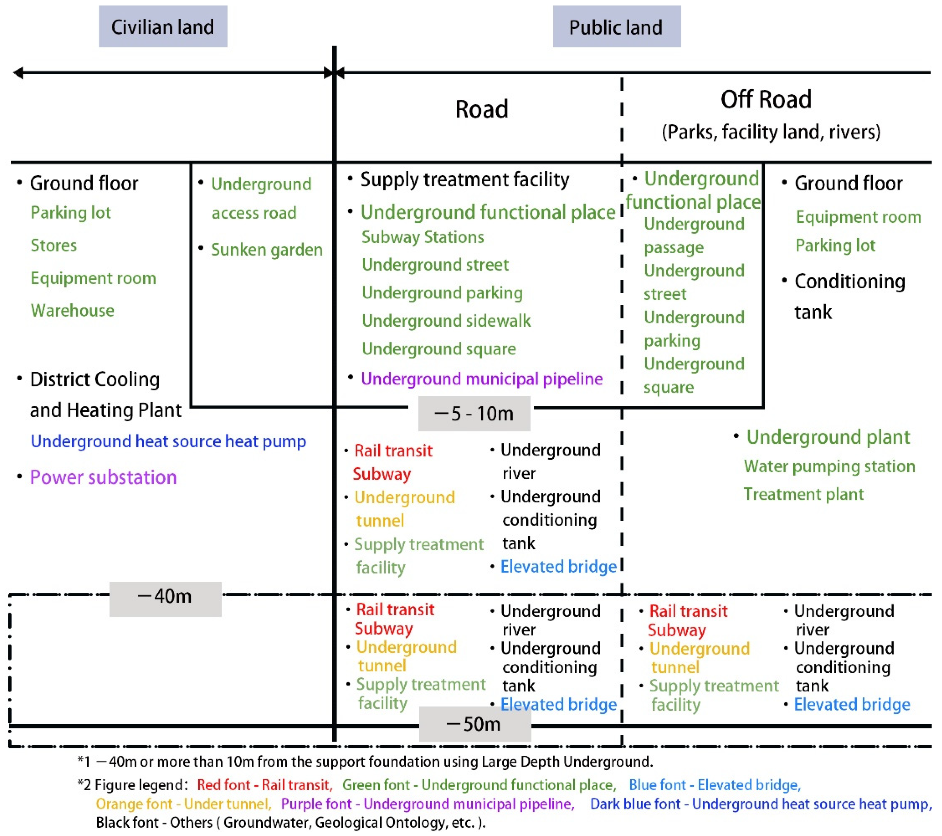
- Classify the underground space according to the classification standard of Japanese underground space and the functional characteristics of each type of underground space, and by clarifying the functional requirements of each type of underground space for sensors on the basis of the classification of underground space;
- Based on the above-mentioned requirements for sensors in the underground space, the sensors are screened on the basis of the temperature and humidity applicable to the underground space, and the sensor types and parameters are selected to meet the smart scene and functional requirements of the underground space;
- Based on the functional requirements met by the above sensors as well as the sensor types and parameters, the types of data acquired by each type of sensor and the data attributes are clarified;
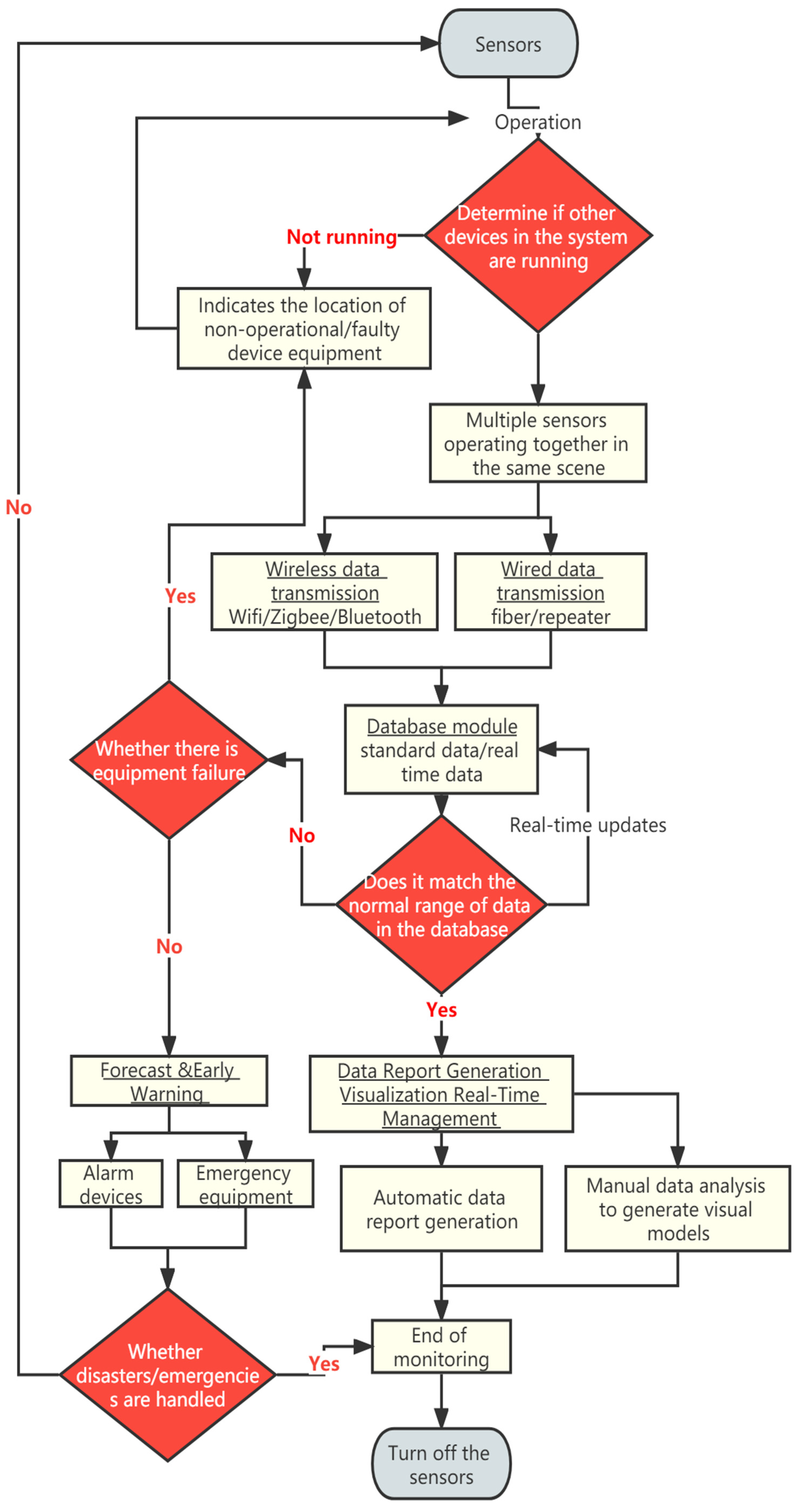
- Based on the classification of underground space, sensor attributes and data attributes in I, II and III above, clarify the data transmission methods and data flow between sensors of various types of data, propose the basic framework of smart sensing system in underground space and form the guidelines for setting up sensors for smart scenes in underground space.
3. Underground Space Classification and Scene Requirements Analysis
4. Underground Space Sensor Sorting
5. Underground Space Data Sorting
6. Basic Framework of Underground Space Smart Sensing Platform
7. Production of Sensor Installation Guidelines for Underground Space
8. Conclusions
Author Contributions
Funding
Institutional Review Board Statement
Informed Consent Statement
Data Availability Statement
Acknowledgments
Conflicts of Interest
References
- Lin, Y.; Shen, Z.; Teng, X. Review on Data Sharing in Smart City Planning Based on Mobile Phone Signaling Big Data: From the Perspective of China Experience: Anonymization Vs De-Anonymization. Int. Rev. Spat. Plan. Sustain. Dev. 2021, 9, 76–93. [Google Scholar] [CrossRef]
- Zhao, L.; Shen, Z.; Zhang, Y.; Ma, Y. The impact of the community built environment on the walking times of residents in a community in the downtown area of Fuzhou. Sustainability 2019, 11, 691. [Google Scholar] [CrossRef]
- Chen, H.; Shen, Z. Building form regulation visualisation in Japan: Automatic building volume legality verification via procedural modelling. Int. J. Sustain. Soc. 2018, 10, 313–340. [Google Scholar] [CrossRef]
- Guo, X.; Shen, Z.; Zhang, Y.; Wu, T. Review on the application of artificial intelligence in smart homes. Smart Cities 2019, 2, 402–420. [Google Scholar] [CrossRef]
- Fitriaty, P.; Shen, Z.; Sugihara, K. How Green Is Your Smart House: Looking Back to the Original Concept of the Smart House. In Green City Planning and Practices in Asian Cities, 1st ed.; Shen, Z., Huang, L., Peng, K., Pai, J., Eds.; Springer: Cham, Switzerland, 2018; Part 1, pp. 39–76. [Google Scholar]
- Nishigaki, M.; Kankam-Yeboah, K.; Komatsu, M. Underground dam technology in some parts of the world. J. Groundw. Hydrol. 2014, 46, 113–130. [Google Scholar] [CrossRef]
- Zhang, Y.; Cheng, J.; Shen, Z.; Liu, S.; Teng, X.; Kawakami, M. Study on the construction of energy-saving evaluation index system for the development of low-carbon industrial—A case study in Pingtan of Fujian Province, China. Energy Rep. 2021, 7, 86–92. [Google Scholar] [CrossRef]
- Dan, Y.; Shen, Z.; Zhu, Y.; Huang, L. Using mixed reality (MR) to improve on-site design experience in community planning. Appl. Sci. 2021, 11, 3071. [Google Scholar] [CrossRef]
- Shen, Z.; Fitriaty, P.; Cao, Z.; Dan, Y. The Evolution and Evaluation Index of Smart House Based on the Comparison with Green House. Shanghai Urban Plan. Rev. 2018, 1, 1–11. [Google Scholar]
- Shen, Z.; Lei, Z.; Li, X.; Sugihara, K. Design Coordination Regarding Urban Design Guidelines Using Google Earth. Int. Rev. Spat. Plan. Sustain. Dev. 2013, 1, 53–68. [Google Scholar] [CrossRef]
- Nguyen, D.-T.; Shen, Z.; Honda, K.; Sugihara, K.; Nishino, T.; Truong, M.-H. A GIS-Based Model for Integrating Risk Estimations of Residential Building Damage and Shelter Capacity in the Case of Earthquakes. Nat. Hazards Rev. 2020, 21, 04019016. [Google Scholar] [CrossRef]
- Tanaka, H.; Kawakami, M.; Shen, Z.; Sekiguchi, T.; Toyoshima, Y. A study on measures for disaster prevention in historically dense Urban areas from the viewpoint of fire spread risk. AIJ J. Technol. Des. 2020, 26, 978–983. [Google Scholar] [CrossRef]
- Teng, X.; Shen, Z. Design of a smart visiting service management system for personal information collection in order to integrate tourism management into an isolated island. Appl. Sci.-Basel 2020, 10, 6442. [Google Scholar] [CrossRef]
- Huang, G.; Shen, Z.; Mardin, R. Overview of Urban Planning and Water-Related Disaster Management. In Urban Planning and Water-related Disaster Management, 1st ed.; Huang, G., Shen, Z., Eds.; Springer: Cham, Switzerland, 2019; Chapter 1; pp. 1–10. [Google Scholar]
- Huang, G.; Shen, Z. Special issue on Environment management and spatial planning. Int. Rev. Spat. Plan. Sustain. Dev. 2017, 5, 1–3. [Google Scholar]
- Li, M.; Dong, L.; Shen, Z.; Lang, W.; Ye, X. Examining the interaction of taxi and subway ridership for sustainable urbanization. Sustainability 2017, 9, 242. [Google Scholar] [CrossRef]
- Çorman, M.E.; Ozcelikay, G.; Cetinkaya, A.; Kaya, S.I.; Armutcu, C.; Özgür, E.; Uzun, L.; Ozkan, S.A. Metal-organic frameworks as an alternative smart sensing platform for designing molecularly imprinted electrochemical sensors. TrAC Trends Anal. Chem. 2022, 150, 116573. [Google Scholar] [CrossRef]
- Park, J.H.; Rathore, S.; Singh, S.K.; Salim, M.M.; Azzaoui, A.E.; Kim, T.W.; Pan, Y.; Park, J.H. A Comprehensive Survey on Core Technologies and Services for 5G Security: Taxonomies, Issues, and Solutions. Hum.-Cent. Comput. Inf. Sci. 2021, 11, 1–22. [Google Scholar]
- Mardin, R.; Shen, Z. Integrated Criteria for Flood Disaster Mitigation in Indonesian Urban Masterplan; Housing and Settlement Suitability Case in Palu Urban Masterplan. In Urban Planning and Water-Related Disaster Management; Springer: Cham, Switzerland, 2019; pp. 127–153. [Google Scholar]
- Sugihara, K.; Shen, Z. Automatic generation of 3D building models by rectification of building polygons. Adv. Sci. Lett. 2015, 21, 3649–3654. [Google Scholar] [CrossRef]
- Long, Y.; Shen, Z. Population Spatialization and Synthesis with Open Data. Geospat. Anal. Support Urban Plan. Beijing 2015, 116, 115–131. [Google Scholar]
- Li, M.; Deng, J.; Liu, L.; Long, Y.; Shen, Z. Evacuation simulation and evaluation of different scenarios based on traffic grid model and high performance computing. Int. Rev. Spat. Plan. Sustain. Dev. 2015, 3, 4–15. [Google Scholar] [CrossRef]
- Zhang, Y.; Zhang, Y.; Shen, Z.; Nishino, T.; Chen, X. 3D laser scanning technology-based historic building mapping for historic preservation A case study of Shang Shu Di in Fujian Province, China. Int. Rev. Spat. Plan. Sustain. Dev. 2015, 3, 53–67. [Google Scholar]
- Guo, X.; Shen, Z.; Teng, X.; Lin, Y. Using Web Data Scraping to Reveal the Relationship between AI Product and Room Layout. In Design and Technological Applications in Sustainable Architecture, 1st ed.; Lau, S.S.Y., Li, J., Hao, S., Lu, S., Eds.; Springer: Cham, Switzerland, 2021; Part 5, pp. 147–158. [Google Scholar]
- Shen, Z.; Ma, Y.; Sugihara, K.; Lei, Z.; Shi, E. Technical possibilities of cloud-based virtual reality implementing software as a service for online collaboration in urban planning. Int’l J. Commun. Netw. Syst. Sci. 2015, 7, 463. [Google Scholar] [CrossRef]
- Gong, S.; Liu, Z.; Guan, S.; Jiao, J.; Shen, Z.; Yang, D.; Sun, S.; Chen, C. Lidar study on the parameter relations of gravity waves in the mesopause region at Beijing. Infrared Laser Eng. 2015, 44, 1134–1140. [Google Scholar]
- Li, M.; Shen, Z.; Yang, T.; Wang, J.; Kobayashi, F.; Li, M. Application of spatial and temporal entropy based on multivariate data for measuring the degree of urban function mix. China City Plan. Rev. 2015, 24, 40–48. [Google Scholar]
- Shen, Z. Overview: Big data support for urban planning and management in China. In Big Data Support of Urban Planning and Management, 1st ed.; Shen, Z., Li, M., Eds.; Springer: Cham, Switzerland, 2018; Chapter 1; pp. 1–15. [Google Scholar]
- Shen, Z.; Kawakami, M. Overview: Spatial Planning for Achieving Sustainable Urban Forms. In Spatial Planning and Sustainable Development, 1st ed.; Kawakami, M., Shen, Z., Gao, X., Zhang, M., Eds.; Springer: Cham, Switzerland, 2013; Chapter 1; pp. 1–11. [Google Scholar]
- Li, M.; Shen, Z.; Sheng, Q.; Duan, B.; Li, L. A study on the correlation between spatial configuration and rail passenger volume in different scales-take Fuxia region as an example. Int. J. Soc. Syst. Sci. 2016, 8, 114–130. [Google Scholar] [CrossRef]
- Alsalemi, A.; Himeur, Y.; Bensaali, F.; Amira, A. Smart Sensing and End-Users’ Behavioral Change in Residential Buildings: An Edge-Based Internet of Energy Perspective. IEEE Sens. J. 2021, 21, 27623–27631. [Google Scholar] [CrossRef]
- Singh, S.K.; Tanwar, S. Analysis of software testing techniques: Theory to practical approach. Indian J. Sci. Technol. 2016, 9, 1–6. [Google Scholar] [CrossRef]
- Zhang, Y.; Shen, Z.; Cui, B.; Lin, Y. Construction of Urban Planning Supporting System Using Genetic Algorithm Responding to Urban Decentralization: Case of Kanazawa City. J. Urban Plan. Dev. 2020, 146, 04020044. [Google Scholar] [CrossRef]


| The Types of Equipment Mentioned in the Guidelines | Rules for Equipment Requirements Mentioned in the Guidelines | Current Use of the Devices |
|---|---|---|
| Lighting Equipment | 1. Requirements on the installation of lighting equipment in three cases: a. Lighting equipment renewal (completely renewed, mixed old and new); b. Lighting equipment operation next to the air exchange fan. 2. Precautions for wiring installation of lighting equipment. 3. Precautions for installation of lighting equipment itself. | LED tunnel light |
| Air Ventilation Equipment | 1. The air exchange equipment is mainly tunnel fans. 2. The location of the anchor for the fan is determined and installation precautions. 3. Precautions for installation of the fan itself. 4. Post-installation testing precautions. | Tunnel jet fan |
| Dust Countermeasure Equipment | 1. Application of air ventilation equipment in the dust response phase. 2. Specific content of dust concentration measurement. 3. Precautions for the use of respiratory protective equipment in emergency situations. | Tunnel jet fan, dust concentration detector |
| Noxious Gas Response Equipment | 1. Requirements for exhaust devices. 2. Requirements for alarm devices (including implementation of monitoring equipment). 3. Response when the critical value is reached (automatic power cut). 4. Requirements for evacuation equipment. | Tunnel jet fans, alarms or emergency bells, Automatic fixed combustible gas alarms, Automatic power cut-off devices |
| Alarm & Rescue Equipment | 1. Clarify the investigation content of the prior investigation. 2. The use of rescue equipment. 3. The use of alarm equipment. | Alarm or emergency bell, automatic fixed combustible gas alarm, smoke detector |
| Disaster Response Equipment | To deal with rain, wind, snow, lightning, earthquakes and other natural disasters | Alarm or emergency bell, automatic fixed combustible gas alarm, automatic power cut-off device |
| Structure Monitoring Equipment | Mainly construction auxiliary equipment. | Earth pressure meter (vibrating string type earth pressure meter), pore water pressure meter, static level, displacement meter, in-clinometer, pillar pressure meter, reinforcement meter/anchor force gauge, concrete strain gauge |
| Environmental Monitoring Equipment | 1. Measures for places with poor ventilation conditions. 2. Measures to deal with the cramped environment during mechanical construction. 3. Measurement required for operating environment. | Automatic fixed combustible gas alarm, smoke detector, thermometer, hygrometer, dust concentration detector |
| Scene Type | Maintenance and Management | Control-Warning | |
|---|---|---|---|
| Daily Maintenance | Disaster Prevention | ||
| Rail transit | Personal safety-fall, Personal safety-attention wake-up, obstacle monitoring, track status monitoring | Flooding disaster, fire evacuation, earthquake disaster | smart construction monitoring, disaster response (fire, flooding, earthquake, gas leak, tilt, subsidence, deformation) |
| Elevated bridge | Structural security monitoring | ||
| Underground tunnel | Structural security monitoring | Tube sheet disease, tunnel flooding disaster, fire evacuation, earthquake disaster | |
| Underground municipal pipeline | Pipeline structure monitoring, pipe chamber environmental monitoring | Pipeline leaks (liquid/gas), underground voids | |
| Underground functional place | Underground space environmental monitoring | Underground space flooding disaster, fire evacuation, earthquake disaster | |
| Underground heat source heat pump | Underground heat source pollution monitoring | ||
| Geological ontology | Surface monitoring, in-ground monitoring | Geological tilt, subsidence, deformation | |
| Ground water | Groundwater level daily monitoring | Groundwater contamination monitoring | Groundwater level, water temperature, water quality abnormalities |
| Smart Scene Type | Requirements | Purpose |
|---|---|---|
| Basic scenes (generic scenes) | Monitoring of natural and man-made disasters | Response before and after disasters, mainly natural disasters (flooding, earthquakes, extreme weather (extreme cold and heat, thunderstorms)) and man-made disasters (fire, equipment failure, construction personnel health) |
| Monitor construction and operational environments | Monitoring and adjusting the air environment, sound environment, geotechnical environment, and light environment to make people feel comfortable | |
| Obtaining staff health information | Prevention of various types of emergencies in the underground space when affecting the health of staff, timely response | |
| Obtain equipment movement information | Prevent the loss of equipment in the underground space or loss of contact with the host | |
| Rail transit | Obtain information on falling objects on the tracks | Prevent people from falling onto the track or objects from falling onto the track and affecting train operation |
| Monitoring of platform doors for objects caught in them | Prevent damage to people or objects when platform doors are closed | |
| Emergency stop of trains | To guide trains to an emergency stop after an emergency situation to reduce damage | |
| Obtain track structure information | Prevent damage to the track structure from affecting operation | |
| Underground functional place | Obtain operating environment data and make timely adjustments | To make the environment comfortable and convenient for various functions |
| Elevated bridge | Obtain bridge structure information | Reducing damage to bridge structures that may affect operations |
| Obtain information on pillar structure | Prevention of collapse due to damage to the column structure | |
| Underground tunnel | Obtain support structure information | Reduce the collapse potential caused by damage such as support cracks, and deal with cracks that have a greater impact in a timely manner |
| Underground municipal pipeline | Real-time monitoring of pipeline structure | Prevent the occurrence of liquid leakage and air leakage, and respond to liquid leakage and air leakage in a timely manner |
| Underground heat source heat pump | Obtain information on pipeline structure | Prevent fluid leaks and respond to them in a timely manner |
| Obtain information on the structure of the exchange well | Reduce collapse hazards caused by cracks in exchange wells, etc., and promptly respond to cracks that have a large impact | |
| Monitoring the fluid in the well | Liquid temperature and water level should meet the specific requirements of the heat source heat pump and reduce the influence of the liquid itself on the efficiency of the heat source heat pump | |
| Obtain information on surrounding groundwater | Reduce the pollution of the surrounding groundwater by the liquid in the exchange well |
| Smart Scene Type | Sensor Type | Detection Principle (Component Equipment) | Data Monitoring Scope | Long-Term/Regular Monitoring |
|---|---|---|---|---|
| Basic scenes (generic scenes) | Infrared smoke sensor | Infrared 2 wavelength type, fluctuation type, CO2 resonance radiation type | Exposure to smoke YES/NO | Long-term monitoring |
| Gas sensors | Hot-wire type semiconductor type, contact combustion type, gas heat conduction type | 0~100% LEL | Long-term monitoring | |
| Hydrogen sulfide sensor | 0~50 ppm | Long-term monitoring | ||
| Carbon monoxide sensor | Constant potential electrolytic type, diaphragm plus Varney cell type | 0~250 ppm | Long-term monitoring | |
| Oxygen sensor | Constant potential electrolytic type, diaphragm plus Varney cell type | 0~25 vol% | Long-term monitoring | |
| Noise detector1 | Condenser electric microphone | 28~141 dB | Long-term monitoring | |
| Flood sensor | Water contact sensor | Exposure to water YES/NO | Long-term monitoring | |
| Temperature and humidity sensor | Capacities temperature and humidity sensitive sensor | Temperature: −40~80 °C Humidity: 0~100%Rh | Long-term monitoring | |
| Mobile environmental monitoring sensor | Constant potential electrolytic type, diaphragm plus Varney cell type | Oxygen concentration: 0~25 vol% | Long-term monitoring | |
| Carbon monoxide concentration: 0~300 ppm | Long-term monitoring | |||
| Laser distance sensor | Light reflection principle | 0.05~100 m | Long-term monitoring | |
| RFID readers/tags | Light reflection principle | 3–5 m | Long-term monitoring | |
| Dust sensor | Light scattering relative density meter | Exposure to dust YES/NO | Long-term monitoring | |
| Wind speed sensor | Rotor rotation speed | 0~114 m/s | Long-term monitoring | |
| Rail transit | Gas sensors | Hot-wire type semiconductor type, contact combustion type, gas heat conduction type, constant potential electrolytic type, diaphragm plus Varney cell type | 0~100% LEL | Long-term monitoring |
| Hydrogen sulfide sensor | 0~50 ppm | Long-term monitoring | ||
| Carbon monoxide sensor | 0~250 ppm | Long-term monitoring | ||
| Oxygen sensor | 0~25 vol% | Long-term monitoring | ||
| Construction monitoring radar | Light reflection principle | Collapse occurs YES/NO | Long-term monitoring | |
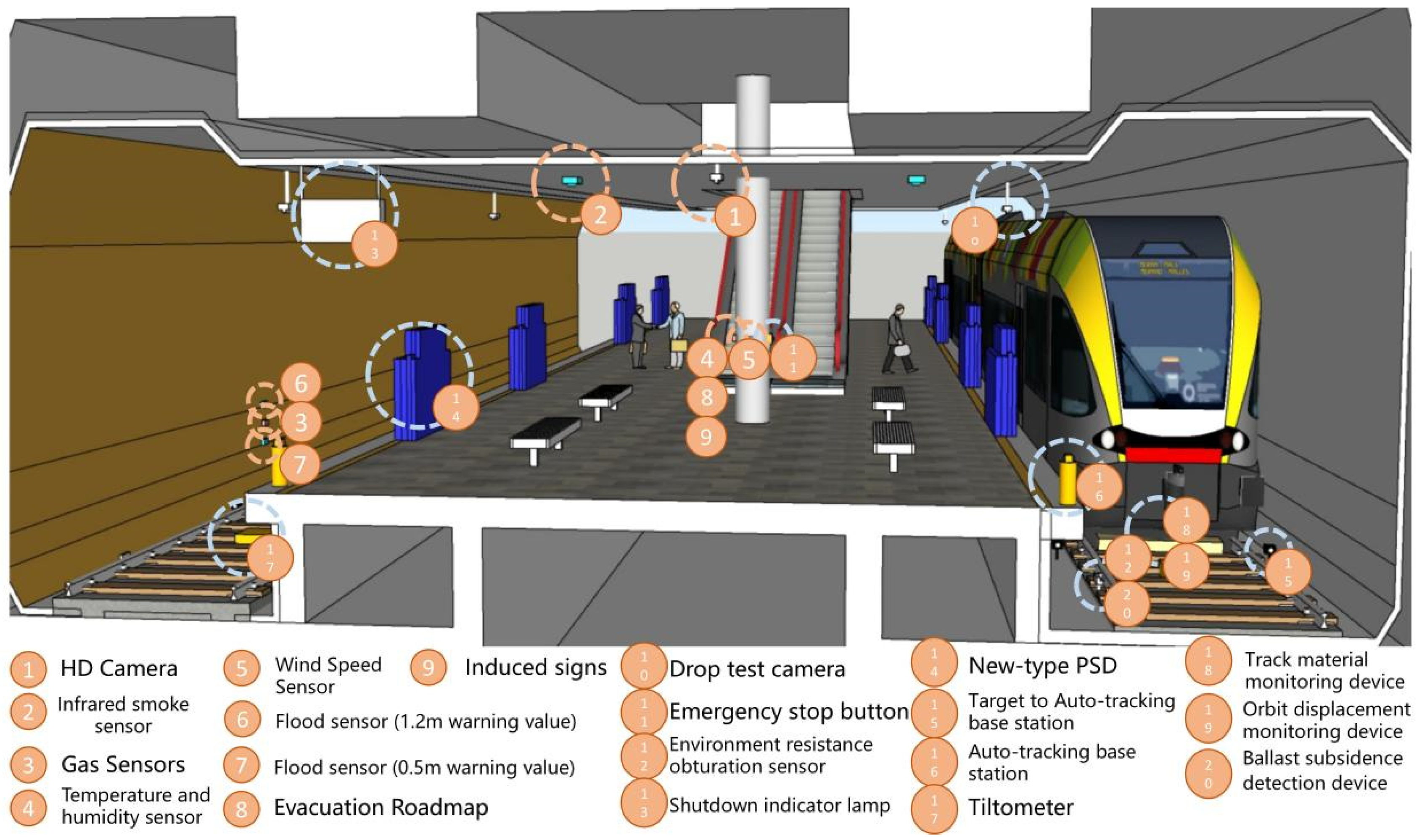
| Roll-off detection mat | Environment resistance obturation sensor, Drop test camera | Perceived pressure YES/NO | Long-term monitoring | |
| New-type PSD | Residual detection sensors (3D sensors, photoelectric sensors), proximity detection sensors (photoelectric sensors) | Perceived pressure YES/NO | Long-term monitoring | |
| Track material monitoring device | Configuration camera (distance image capture device) | Material Breakage YES/NO | Regular monitoring | |
| Orbit displacement monitoring device | Linear sensor camera (Intense and faint image photography device) | Orbital displacement YES/NO | Regular monitoring | |
| Image displacement measurement system | Laser displacement meter | Orbital displacement YES/NO | Regular monitoring | |
| Line equipment monitoring device | Digital camera, displacement meter, in-clinometer | Equipment breakage YES/NO | Regular monitoring | |
| Underground functional place | Dust sensor | Light scattering relative density meter | Exposure to dust YES/NO | Long-term monitoring |
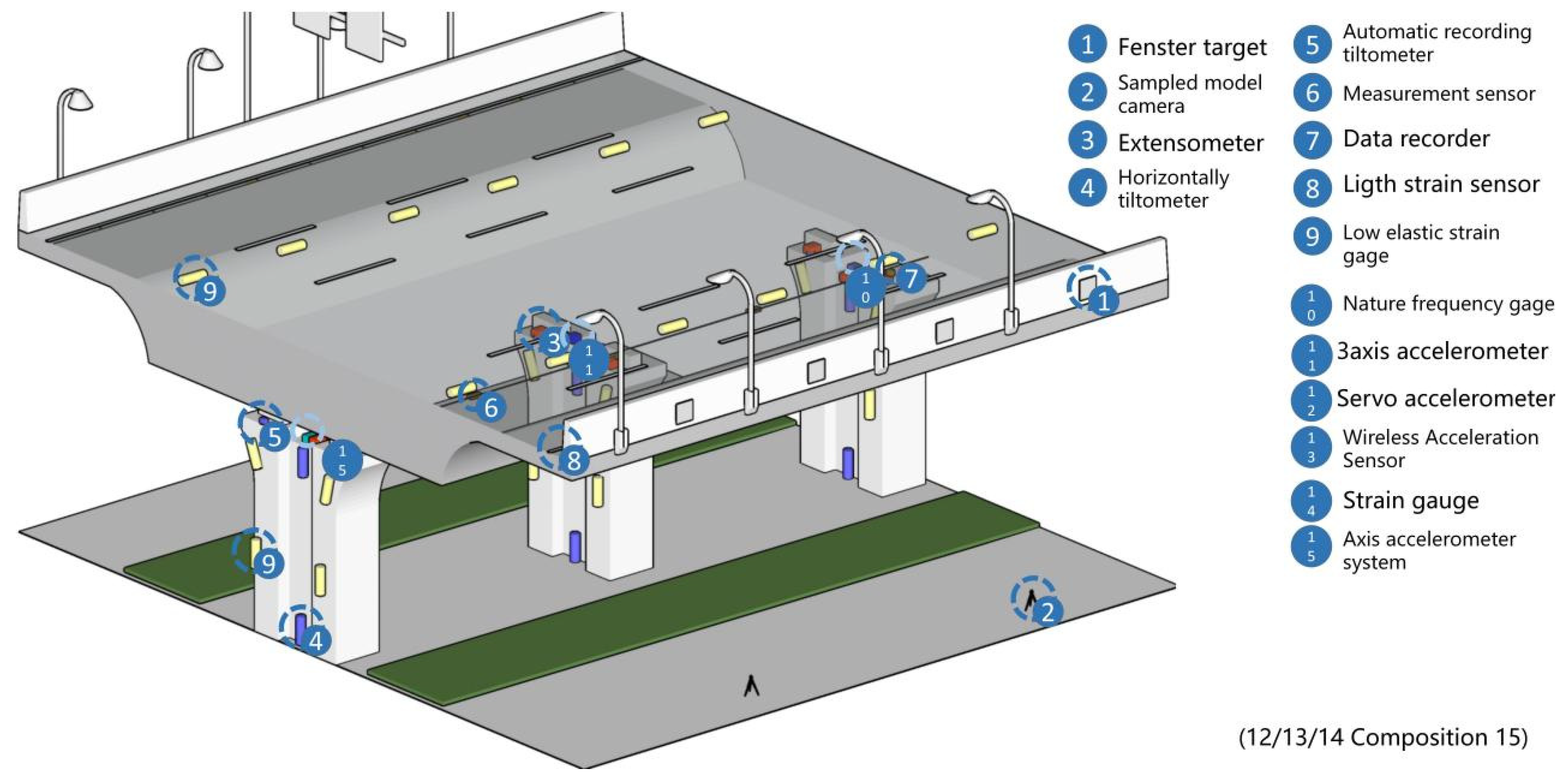
| Elevated bridge | Extensometer | Displacement sensor | 6.5 ± 1 mm | Long-term monitoring |
| Horizontally tiltometer | Tiltmeter | 0–500 mm | Long-term monitoring | |
| Crack gauge | Crack gauge | 5~40% | Long-term monitoring | |
| Light strain sensor | Light strain sensor, Strain gauge, Fiber optic measuring instrument | Sensing to strain YES/NO | Long-term monitoring | |
| Nature frequency gage | Nature frequency gage | 50 kHz | Regular monitoring | |
| Underground tunnel | Gas sensors | Hot-wire type semiconductor type, contact combustion type, gas heat conduction type, constant potential electrolytic type, diaphragm plus Varney cell type | 0~100% LEL | Long-term monitoring |
| Hydrogen sulfide sensor | 0~50 ppm | Long-term monitoring | ||
| Carbon monoxide sensor | 0~250 ppm | Long-term monitoring | ||
| Oxygen sensor | 0~25 vol% | Long-term monitoring | ||
| Construction monitoring radar | Light reflection principle | Collapse occurs YES/NO | Long-term monitoring | |
| Crack displacement meter | Crack displacement meter, remote wireless unit | 5~40% | Long-term monitoring | |
| Fiber optic crack detection sensor | Crack detection accelerometer, crack detection adapter, data recorder TDS-530 | 5~40% | Long-term monitoring | |
| Fiber optic sensor | Fiber optic sensor | Cracking occurs YES/NO | Long-term monitoring | |
| Underground municipal pipeline | Water leak detection service | Water leak detection sensor | Water leakage occurs YES/NO | Long-term monitoring |
| Remote water leak monitoring system | Water leak detection sensor | Water leakage occurs YES/NO | Long-term monitoring | |
| Installation of tube lumen survey machine | Electromagnetic pulse radar, television cameras | Tube lumen breakage YES/NO | Regular monitoring | |
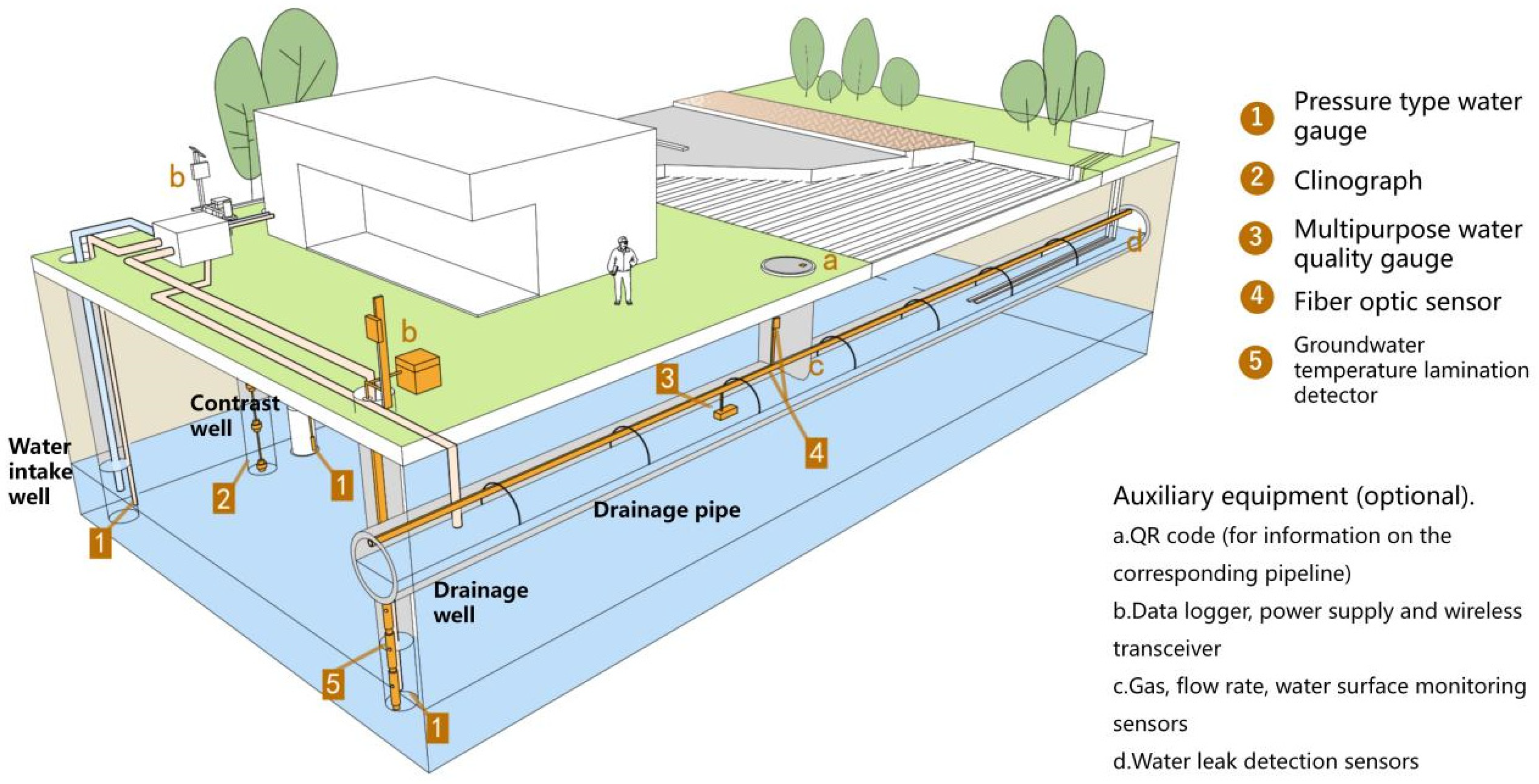
| Underground heat source heat pump | Pressure type water gauge | Induction of hydro-static pressure in water bodies | 0.05% F.S | Long-term monitoring |
| Clinograph | Tilt sensor, electrolyte and conductive contacts | ±330 micro-radius | Long-term monitoring | |
| Multipurpose water quality gauge | Voltage conductivity | PH value | Long-term monitoring | |
| Water leak detection sensor | Laser hydrostatic principle | 0–50 m | Long-term monitoring |
| Smart Scene Type | Sensor Type | Data Monitoring Scope | Monitoring Indicator | Data Transmission Method |
|---|---|---|---|---|
| Basic scenes (generic scenes) | Infrared smoke sensor | Exposure to smoke YES/NO | Smoke, thermal infrared | ZigBee/Bluetooth |
| Gas sensors | 0~100% LEL | Hydrogen concentration, sulfur dioxide gas concentration, carbon dioxide gas concentration | ZigBee/Bluetooth | |
| Hydrogen sulfide sensor | 0~50 ppm | Hydrogen sulfide gas concentration | ZigBee/Bluetooth | |
| Carbon monoxide sensor | 0~250 ppm | Carbon monoxide gas concentration | ZigBee/Bluetooth | |
| Oxygen sensor | 0~25 vol% | Oxygen concentration | ZigBee/Bluetooth | |
| Noise detector | 28~141 dB | Noise intensity | WiFi/Bluetooth | |
| Flood sensor | Exposure to water YES/NO | Flooding depth | WiFi/Bluetooth | |
| Temperature and humidity sensor | Temperature: −40~80 ℃ Humidity: 0~100% Rh | Temperature & Humidity | WiFi/Bluetooth | |
| Mobile environmental monitoring sensor | Oxygen concentration: 0~25 vol% | Oxygen concentration, Carbon monoxide gas concentration | WiFi/Repeater/Bluetooth | |
| Carbon monoxide concentration: 0~300 ppm | ||||
| Laser distance sensor | 0.05~100 m | Distance of mobile devices from the perimeter | Repeater-Bluetooth | |
| RFID readers/tags | 3–5 m | Location, trajectory | WiFi/Bluetooth/USB | |
| Dust sensor | Exposure to dust YES/NO | Dust concentration (PM2.5 mainly) | WiFi/Repeater/Bluetooth | |
| Dust sensor | Exposure to dust YES/NO | Dust concentration | WiFi/Repeater/Bluetooth | |
| Wind speed sensor | 0~114 m/s | Wind speed | WiFi/Repeater/Bluetooth | |
| Rail transit | Gas sensors | 0~100% LEL | Hydrogen concentration, sulfur dioxide gas concentration, carbon dioxide gas concentration | WiFi/Bluetooth |
| Hydrogen sulfide sensor | 0~50 ppm | Hydrogen sulfide gas concentration | ||
| Carbon monoxide sensor | 0~250 ppm | Carbon monoxide gas concentration | ||
| Oxygen sensor | 0~25 vol% | Oxygen concentration | ||
| Construction monitoring radar | Collapse occurs YES/NO | Construction safety (construction environment) | Repeater-Bluetooth | |
| Roll-off detection mat | Perceived pressure YES/NO | Orbital drop | Fiber optic | |
| New-type PSD | Perceived pressure YES/NO | Rail platform gap | Fiber optic | |
| Track material monitoring device | Material Breakage YES/NO | Track material | Repeater | |
| Orbit displacement monitoring device | Orbital displacement YES/NO | Orbital displacement distance | Repeater | |
| Image displacement measurement system | Orbital displacement YES/NO | Orbital displacement distance | Repeater | |
| Line equipment monitoring device | Equipment breakage YES/NO | Wires on the track | Repeater | |
| Underground functional place | Dust sensor | Exposure to dust YES/NO | Dust concentration | WiFi/Repeater/Bluetooth |
| Elevated bridge | Extensometer | 6.5 ± 1 mm | Bridge support displacement distance | Repeater-WiFi |
| Horizontally tiltometer | 0–500 mm | Inclined amount of bridge | Repeater-WiFi | |
| Crack gauge | 5~40% | Crack width of bridge body | Repeater-WiFi | |
| Light strain sensor | Sensing to strain YES/NO | Bridge strain variables | Repeater-WiFi | |
| Nature frequency gage | 50 kHz | Vibration characteristics of the bridge | Repeater-WiFi | |
| Underground tunnel | Gas sensors | 0~100% LEL | Hydrogen concentration, sulfur dioxide gas concentration, carbon dioxide gas concentration | WiFi/Bluetooth |
| Hydrogen sulfide sensor | 0~50 ppm | Hydrogen sulfide gas concentration | ||
| Carbon monoxide sensor | 0~250 ppm | Carbon monoxide gas concentration | ||
| Oxygen sensor | 0~25 vol% | Oxygen concentration | ||
| Construction monitoring radar | Collapse occurs YES/NO | Construction safety (construction environment) | Repeater-Bluetooth | |
| Crack displacement meter | 5~40% | Tunnel support cracks | Repeater-WiFi | |
| Fiber optic crack detection sensor | 5~40% | Tunnel support cracks | Repeater-WiFi | |
| Fiber optic sensor | Cracking occurs YES/NO | Tunnel support strain variables | Repeater-WiFi | |
| Underground municipal pipeline | Water leak detection service | Water leakage occurs YES/NO | Pipeline liquid leakage | Repeater-WiFi |
| Remote water leak monitoring system | Water leakage occurs YES/NO | Pipeline liquid leakage | Repeater-WiFi | |
| Installation of tube lumen survey machine | Tube lumen breakage YES/NO | Pipeline structure | Repeater-WiFi | |
| Underground heat source heat pump | Pressure type water gauge | 0.05% F.S | Heat source heat pump feed well water level, water temperature | Repeater-WiFi |
| Clinograph | ±330 micro-radius | Sliding surface depth, sliding direction and movement of heat source heat pump feeder wells | Repeater-WiFi | |
| Multipurpose water quality gauge | PH value | Water quality changes in heat source heat pump drainage wells | Repeater-WiFi | |
| Water leak detection sensor | 0–50 m | Location and flow conditions of groundwater fluidized bed of heat source heat pump | Repeater-WiFi |
| Smart Scene Type | Smart Scene Function | Sensor Type | Suitable Installation Location | Installation Method | Testing Requirements |
|---|---|---|---|---|---|
| Basic scenes (generic scenes) | Real-time monitoring of the operating and construction environment | Gas sensors | Support left and right wall, place left and right wall/column | Excavation: the amount of excavated soil and the amount of soil transportation (earth calculation) need to be clarified; Retaining support construction: thoroughly check excavation depth, soil quality, groundwater level, working soil pressure, etc., including installation of measuring equipment. | Earth calculation after excavation in construction (excavation volume, discharge and excavation volume, construction progress (excavation depth)); Trial run: power test, lighting test, various equipment operation test, environmental suitability test. |
| Hydrogen sulfide sensor | Support left and right wall, place left and right wall/column | ||||
| Carbon monoxide sensor | Support left and right wall, place left and right wall/column | ||||
| Oxygen sensor | Support left and right wall, place left and right wall/column | ||||
| Noise detector | Support left and right wall, place left and right wall/column | ||||
| Temperature and humidity sensor | Support left and right wall, place left and right wall/column | ||||
| Mobile environmental monitoring sensor | Staff members wear them everywhere | ||||
| Dust sensor | Support left and right wall, place left and right wall/column, construction site floor | ||||
| Wind speed sensor | Support left and right wall, place left and right wall/column | ||||
| Monitor all kinds of emergencies | Flood sensor | Vertical safety distance of support/side wall from the ground | |||
| Infrared smoke sensor | Top of support, top of place safety distance of support/side wall from the ground | ||||
| Get device movement information | Laser distance sensor | Placement with mobile devices | |||
| RFID readers/tags | Readers: Placement with mobile devices; Tags: Top of support/place | ||||
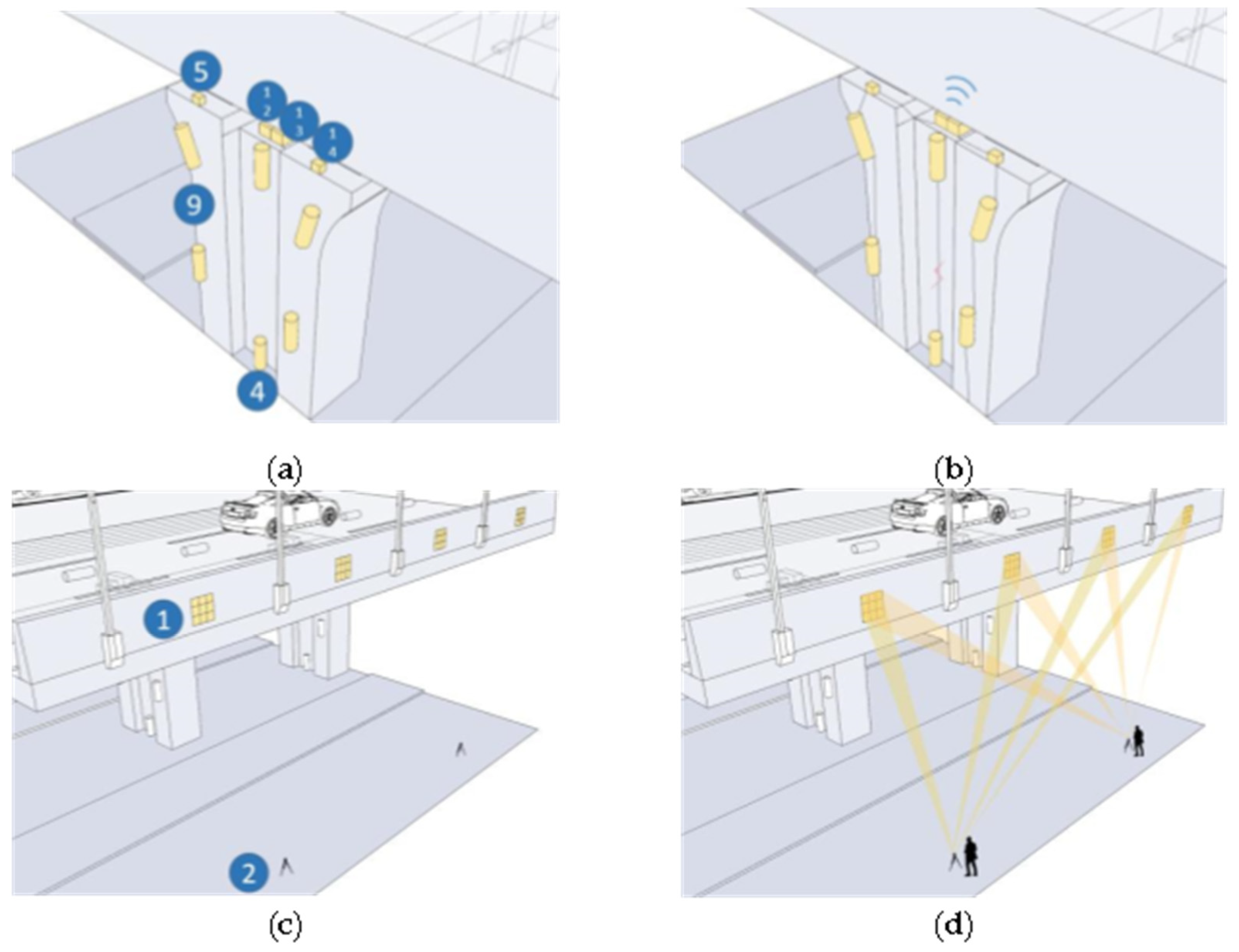
| Rail transit | Real-time construction monitoring | Construction monitoring radar | Ground (near construction site) | Underground diaphragm wall method: prevention of excavation wall collapse, attention to the construction environment geotechnical structure. Weathervane work method: after the structure confirms the foundation support by foundation endurance test, it fills the concrete filled in the working chamber in a dry environment. Shield construction method: excavation is carried out using an excavator, and then a block called a section is installed on the wall to construct a tunnel, and the excavation and discharge of sand and soil is carried out continuously. | 1. Electricity test after the dentsu project (electric communication security); 2. Track commissioning test. |
| Response to falling rail accidents | Roll-off detection mat | Both sides of the track | |||
| Drop test camera | Top of the wall directly above the platform door | ||||
| Response to platform door accidents | New-type PSD | Both sides of the platform near the train | |||
| Orbital structure information acquisition | Track material monitoring device | Mounted with the bottom of the train | |||
| Orbit displacement monitoring device | Mounted with the bottom of the train | ||||
| Image displacement measurement system | Mounted with the bottom of the train | ||||
| Line equipment monitoring device | Mounted with the bottom of the train | ||||
| Underground functional place | Obtain and adjust operational environment data | Dust sensor | The left and right walls/columns of the place, the ground of the personnel gathering area can be placed separately | Same as basic scenes | Earthwork calculation after excavation; Trial run is based on environmental suitability test. There are differences in the requirements of the commissioning equipment according to the function. |
| Elevated bridge | Obtain bridge structure information | Extensometer | Contact part between column and bridge body | Ground drilling method: mainly soft foundation. As a general local piling construction method is the auger construction method; Shell method: mainly hard foundation. Swing and press into the outer cover hose within the full length of the pile. Mainly need to prevent the foundation from collapse. | Same as basic scenes |
| Horizontally tiltometer | Mounted on the column | ||||
| Crack gauge | Vulnerable points on columns/bridge deck | ||||
| Light strain sensor | Bridge side (side wall) | ||||
| Nature frequency gage | Contact part between column and bridge body | ||||
| Underground tunnel | Real-time construction monitoring | Construction monitoring radar | Ground (near construction site) | Shield construction method: continuous excavation and discharge of sand and soil is required; Earth cutting: to prevent subsidence, groundwater protrusion and inflow of soil and sand into the end well, reinforcement and improvement of the soil around the cavern ring are required; Soil cutting volume: the cutting soil and sand must be discharged exactly in line with the amount of excavation; 4. Equipment: the shield machine has the feature that it can only enter but not retreat, so pay attention to the construction status of the shield machine. | Same as basic scenes |
| Obtain information on support structures | Crack displacement meter | Support sidewalls (near sidewall lines) | |||
| Fiber optic crack detection sensor | Support sidewalls (near sidewall lines) | ||||
| Fiber optic sensor | Support sidewalls (near sidewall lines) | ||||
| Underground municipal pipeline | Real-time monitoring of pipeline structures | Water leak detection service | Liquid pipeline vulnerability point (turning point) | For PC grouting, grout mixers, grout pumps, flow meters (grout flow meters) and, in some cases, grouting equipment are used. | There are various tests such as PC grouting temperature measurement, chloride ion content, compressive strength, archeology test, etc. |
| Remote water leak monitoring system | Liquid pipeline vulnerability point (turning point) | ||||
| Installation of tube lumen survey machine | Inside the liquid pipeline | ||||
| Underground heat source heat pump | Obtain information about the structure in the exchange well | Clinograph | Exchange well interior side wall | 1. Pipeline part. ① Confirmation of pipeline paths for misconnection. ② checking the depth of buried pipeline; ③ implementing water pressure test. ④ laying of buried marker plate. ⑤ setting buried markers on the ground surface. ⑥ Confirming the construction around the header. 2. Heat exchange well section. ① Capture geological information Record in excavation. ② Simultaneous setting confirmation of water tension in the underground heat ex-changer, proper reloading, and thermometer setting at insertion. | Trial run: thermal response test, pipe wall temperature test, exchange well temperature and humidity test, flow test, power test, water pressure test |
| Monitoring of fluid in exchange wells | Multipurpose water quality gauge | Liquid in the well | |||
| Pressure type water gauge | Liquid in the well | ||||
| Real-time monitoring of pipeline structures | Water leak detection service | Liquid pipeline vulnerability point (turning point) | |||
| Get information on surrounding groundwater | Water leak detection sensor | Groundwater after borehole |
Publisher’s Note: MDPI stays neutral with regard to jurisdictional claims in published maps and institutional affiliations. |
© 2022 by the authors. Licensee MDPI, Basel, Switzerland. This article is an open access article distributed under the terms and conditions of the Creative Commons Attribution (CC BY) license (https://creativecommons.org/licenses/by/4.0/).
Share and Cite
Shen, Z.; Teng, X.; Zhang, Y.; Fang, G.; Xu, W. Guidelines for Installation of Sensors in Smart Sensing Platforms in Underground Spaces. Sensors 2022, 22, 3215. https://doi.org/10.3390/s22093215
Shen Z, Teng X, Zhang Y, Fang G, Xu W. Guidelines for Installation of Sensors in Smart Sensing Platforms in Underground Spaces. Sensors. 2022; 22(9):3215. https://doi.org/10.3390/s22093215
Chicago/Turabian StyleShen, Zhenjiang, Xiao Teng, Yuntian Zhang, Guoan Fang, and Wei Xu. 2022. "Guidelines for Installation of Sensors in Smart Sensing Platforms in Underground Spaces" Sensors 22, no. 9: 3215. https://doi.org/10.3390/s22093215
APA StyleShen, Z., Teng, X., Zhang, Y., Fang, G., & Xu, W. (2022). Guidelines for Installation of Sensors in Smart Sensing Platforms in Underground Spaces. Sensors, 22(9), 3215. https://doi.org/10.3390/s22093215