
Multipath-Assisted Radio Sensing and State Detection for the Connected Aircraft Cabin †


Abstract
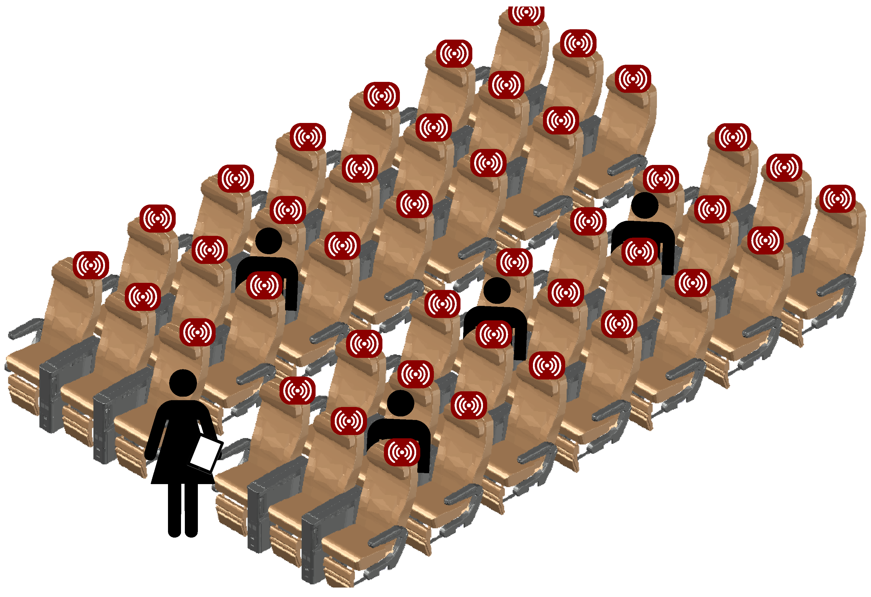
:1. Introduction
1.1. Status Quo of Sensors inside the Connected Cabin
1.2. Radio Sensing for Connected Cabin
1.3. Focus and Structure of the Article
- The discussion of the applicability of radio sensing within the connected aircraft cabin, including passenger seat occupancy detection for boarding monitoring and automated cabin and passenger safety checks.
- The derivation and application of CIR-based state detection methods for this application, including probabilistic filtering for spatial mapping and kNN.
- An empirical measurement survey using Ultra-Wideband devices using an aircraft seat mockup in both an anechoic chamber under close to ideal conditions and a laboratory environment in order to evaluate the proposed methods.
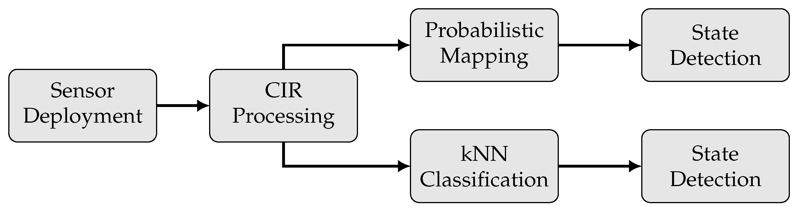
2. Problem Formulation
3. Multipath-Assisted Radio Sensing (MARS)
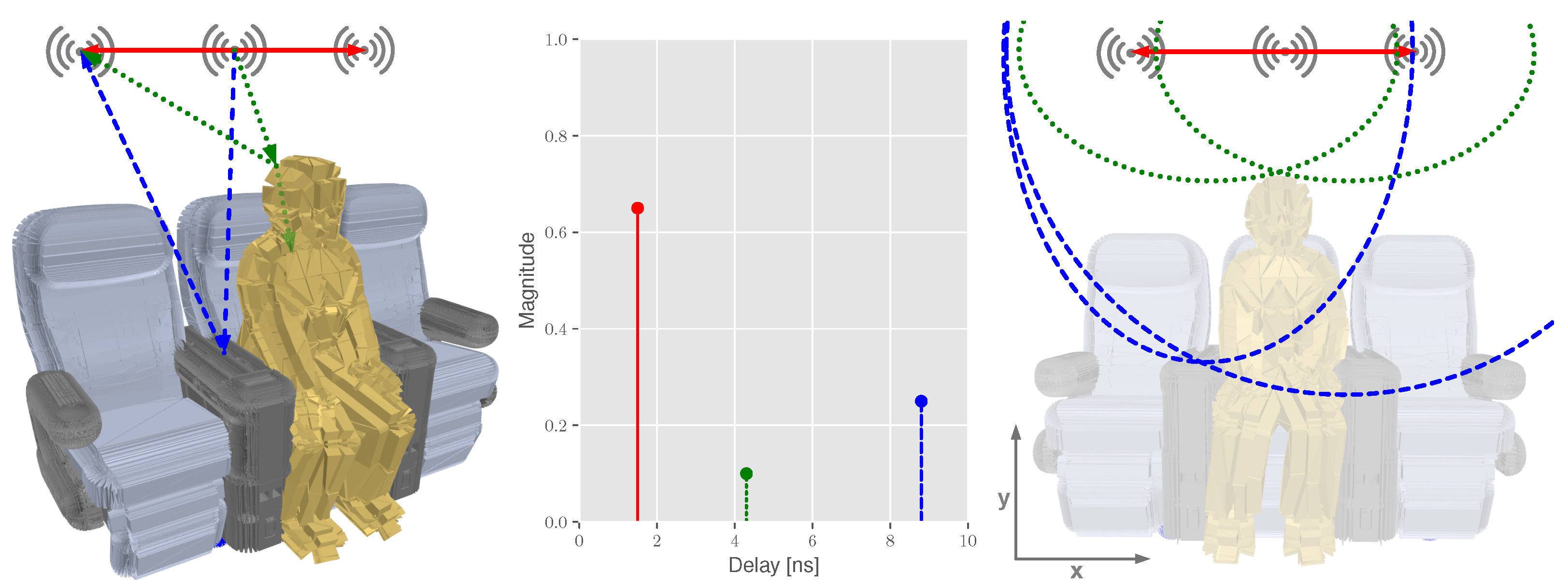
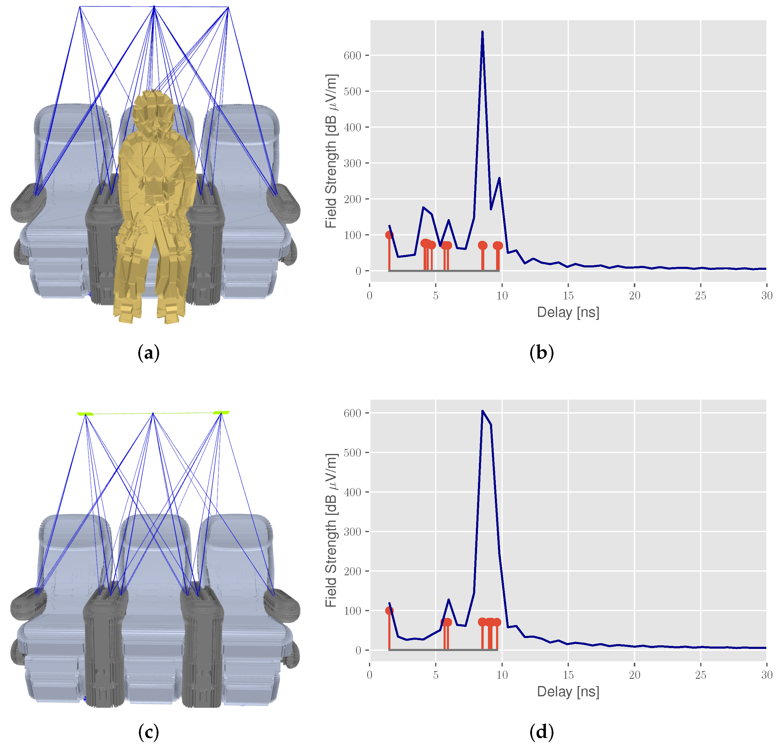
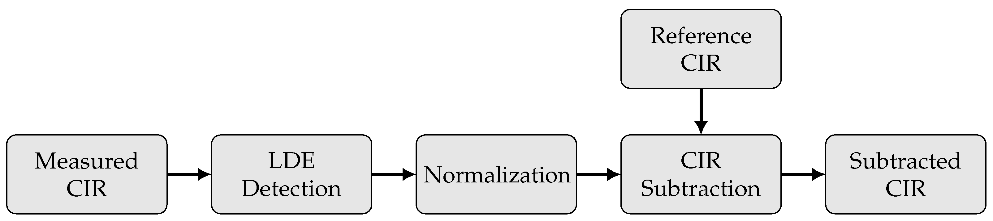
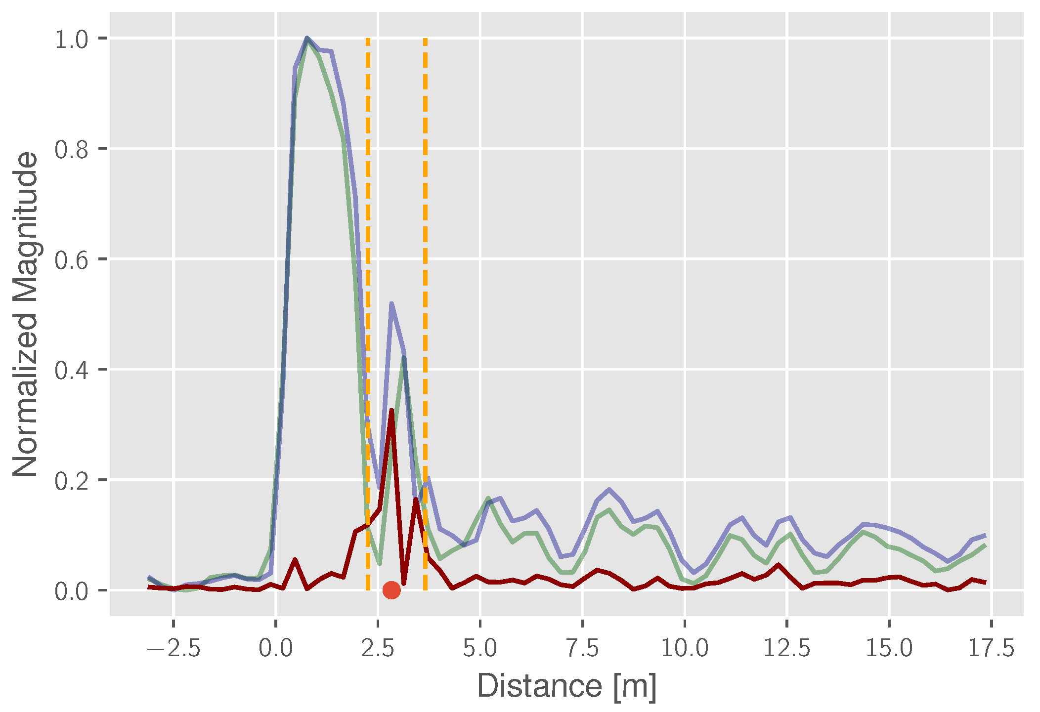
3.1. Channel Impulse Response
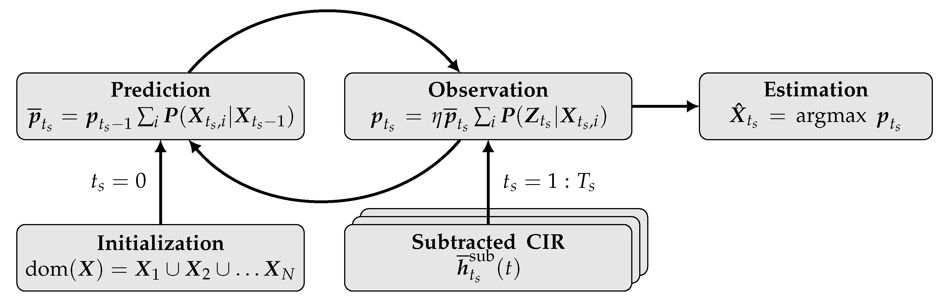
3.2. Probabilistic Grid Mapping
- The determinacy of the equation system: with only two transmitter–receiver relations for each seat row and the assumption of a two-dimensional unknown target position , the ellipses intersection is ambiguous.
- Multi-modality: due to the aforementioned ambiguity, in combination with a poor geometric constellation, multi-modalities in the state space are likely to occur, which hurt the presumptions of parametric state estimation.
| Algorithm 1: Probability Grid Mapping—Likelihood Calculation. |
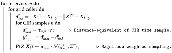 |
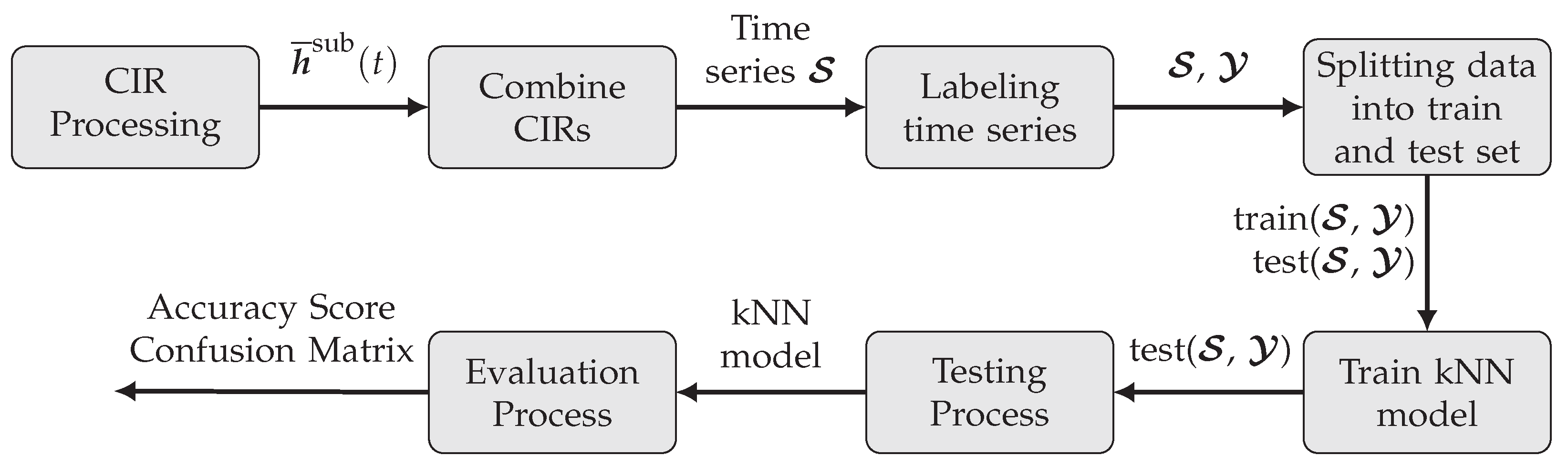
3.3. kNN Classification
- The quality of the input data and noise in the training dataset;
- The number of classes in the dataset;
- The size of the training dataset;
- The number k of nearest neighbors considered for the classification;
- The choice of the distance metric.
4. Results and Discussion
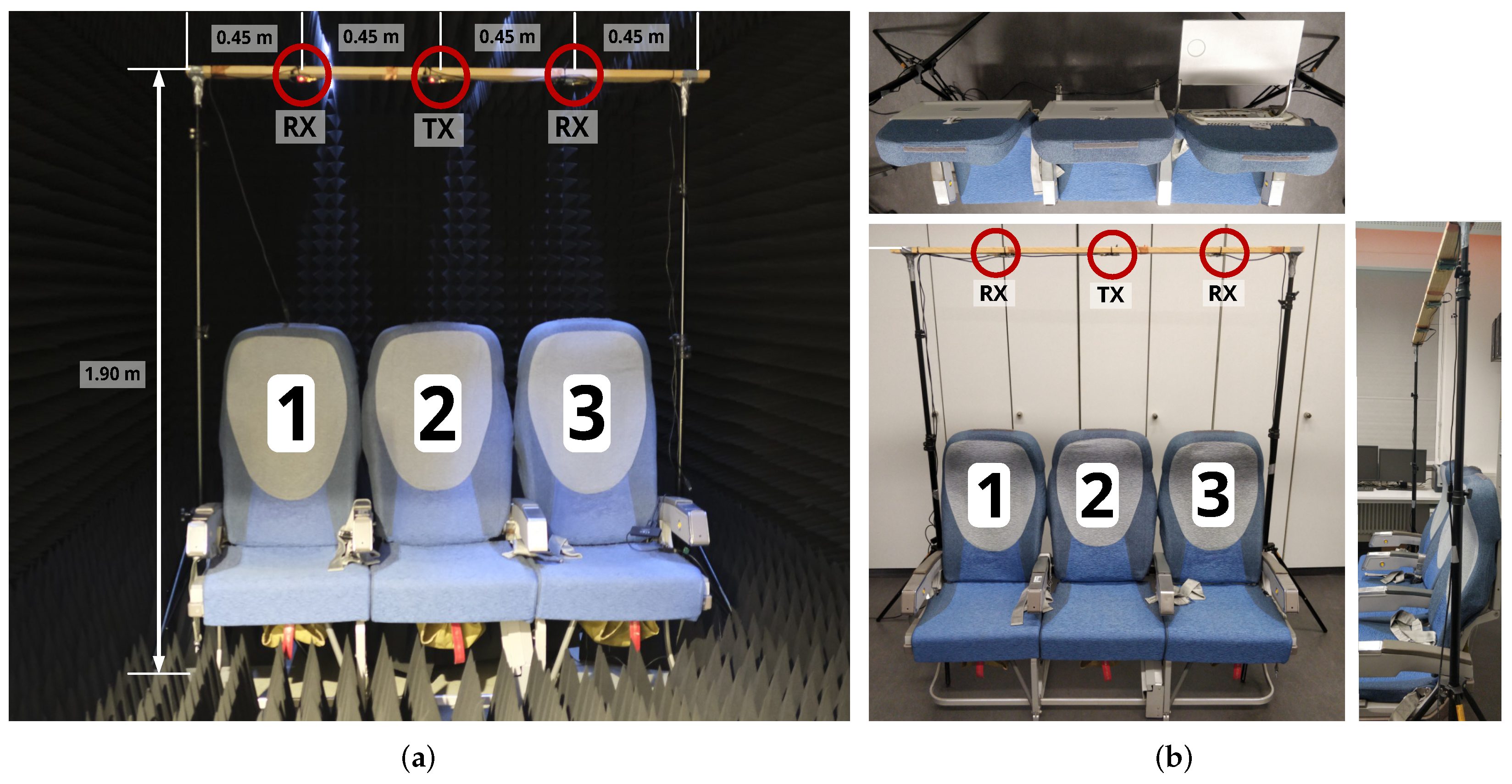
4.1. Measurement Setup and Datasets
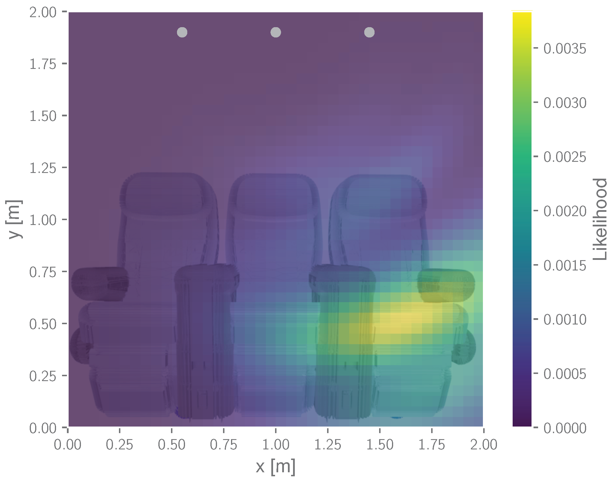
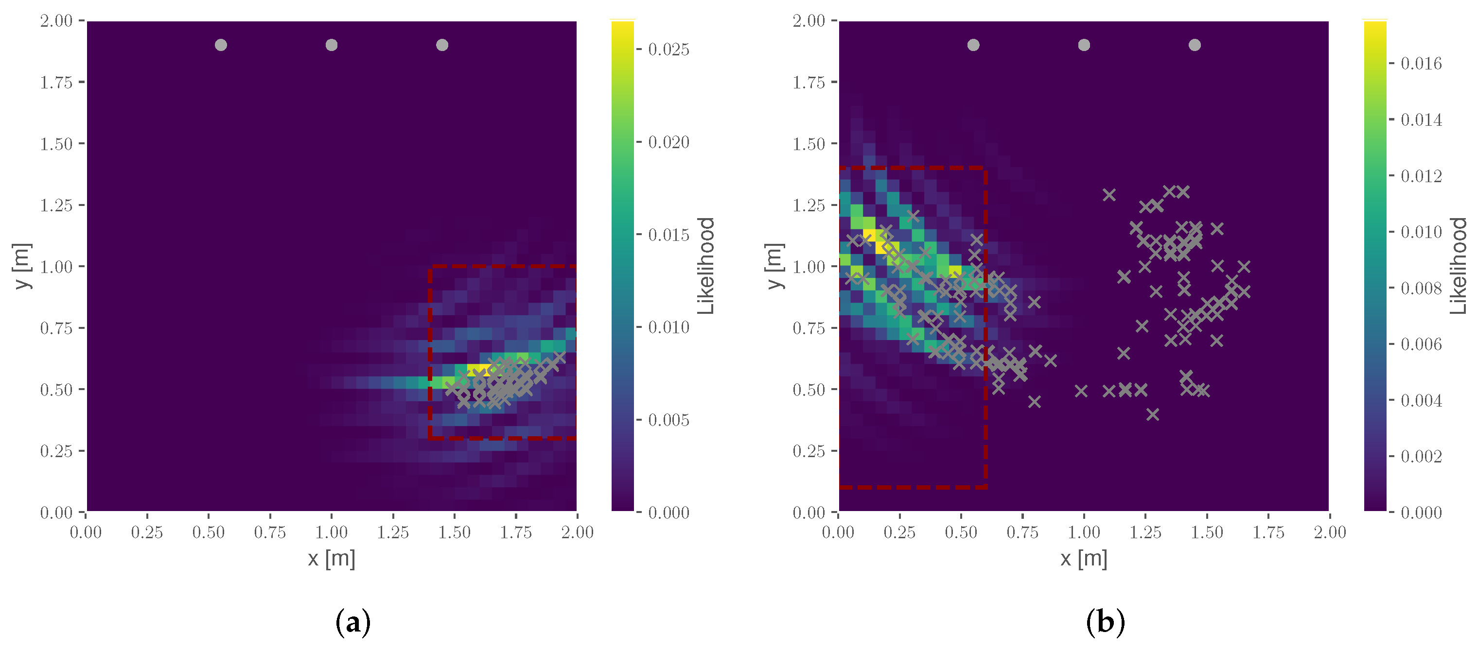
4.2. Probabilistic Grid Mapping
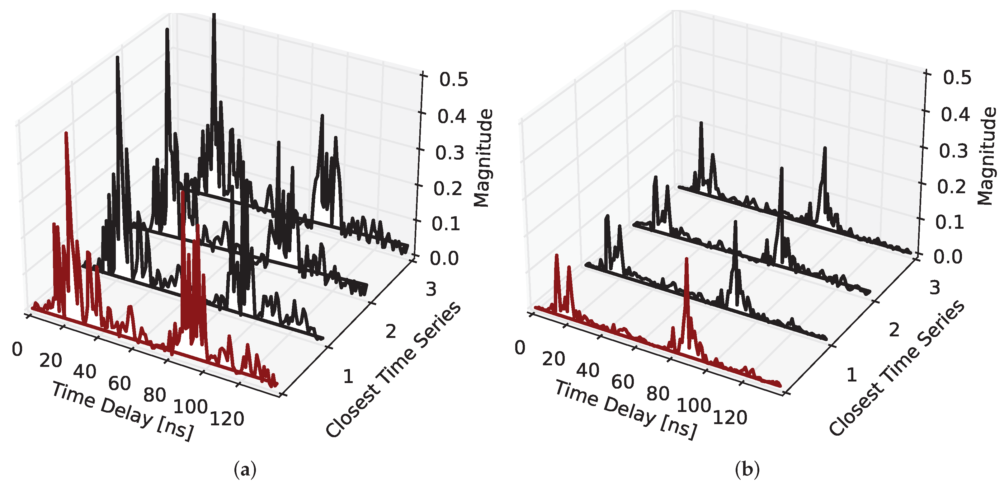
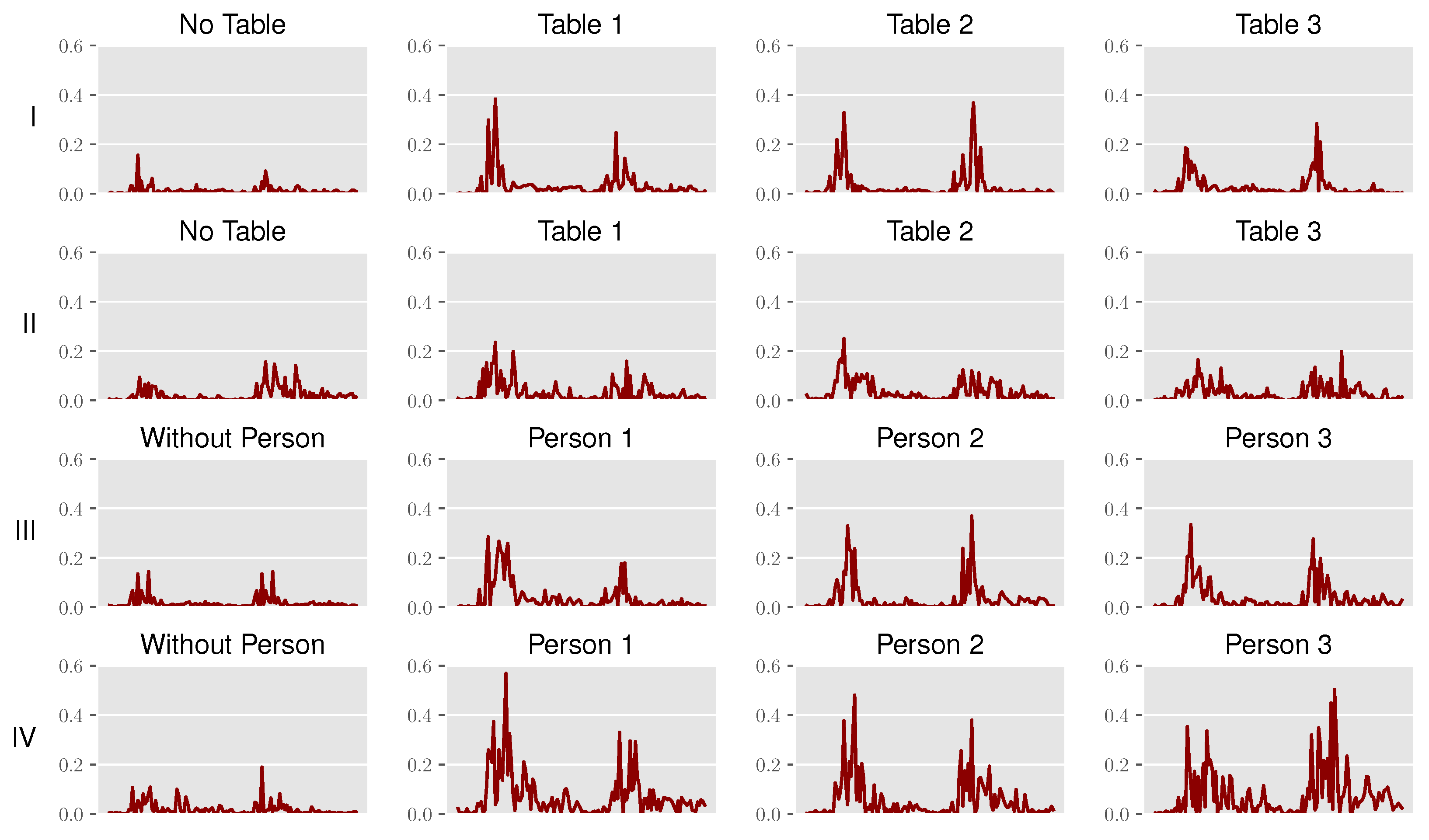
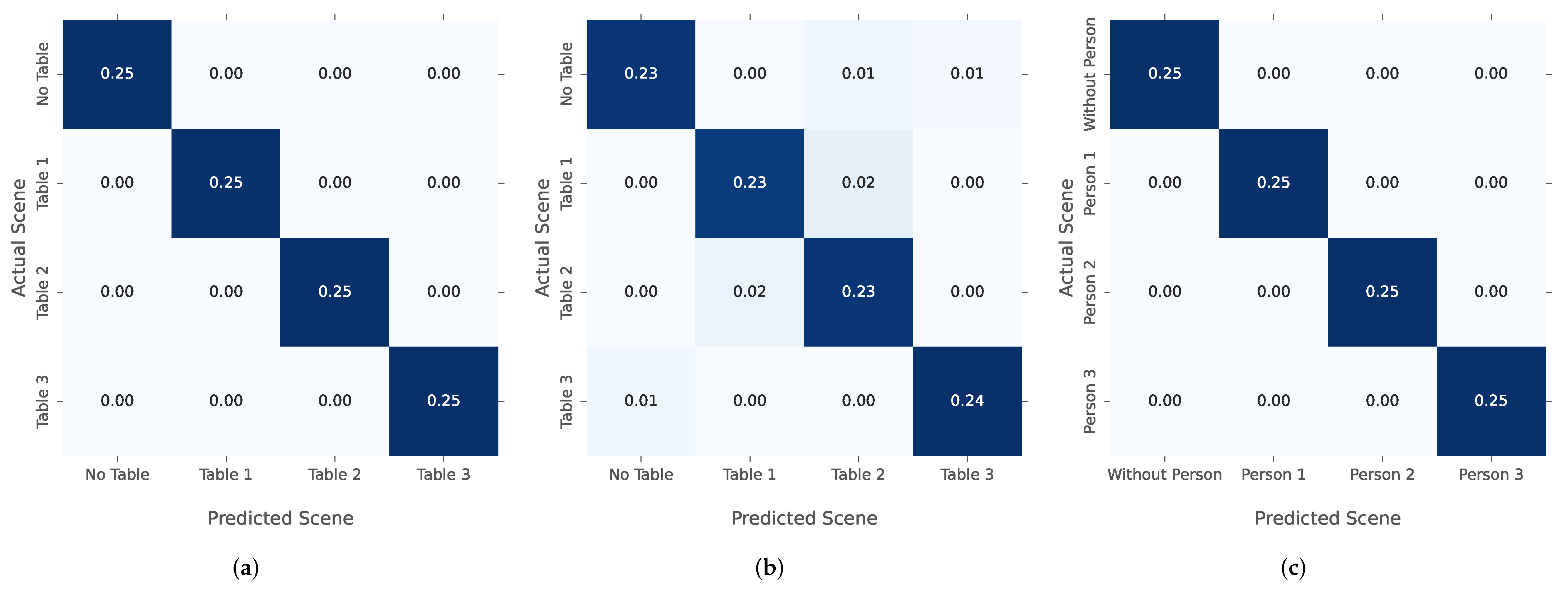
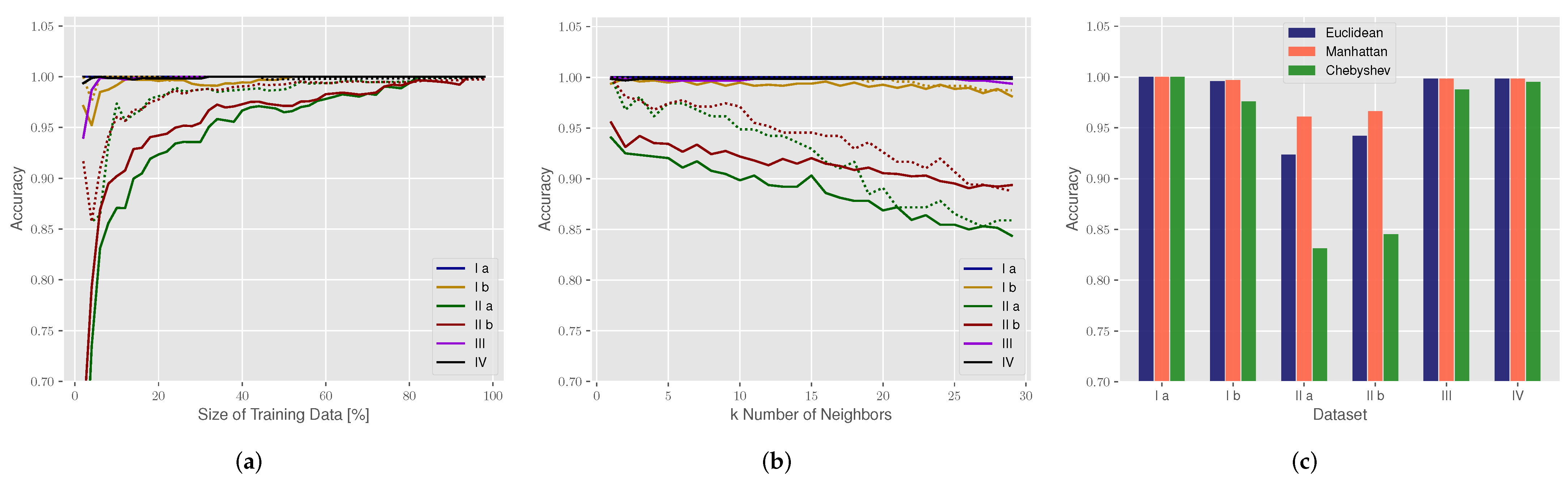
4.3. Classification
5. Conclusions and Outlook
Author Contributions
Funding
Institutional Review Board Statement
Informed Consent Statement
Data Availability Statement
Conflicts of Interest
References
- Schultz, M. Fast Aircraft Turnaround Enabled by Reliable Passenger Boarding. Aerospace 2018, 5, 8. [Google Scholar] [CrossRef] [Green Version]
- Schwarzbach, P.; Engelbrecht, J.; Michler, A.; Schultz, M.; Michler, O. Evaluation of Technology-Supported Distance Measuring to Ensure Safe Aircraft Boarding during COVID-19 Pandemic. Sustainability 2020, 12, 8724. [Google Scholar] [CrossRef]
- Schmidt, J.F.; Neuhold, D.; Bettstetter, C.; Klaue, J.; Schupke, D. Wireless Connectivity in Airplanes: Challenges and the Case for UWB. IEEE Access 2021, 9, 52913–52925. [Google Scholar] [CrossRef]
- Zheng, L.; Lops, M.; Eldar, Y.C.; Wang, X. Radar and Communication Coexistence: An Overview: A Review of Recent Methods. IEEE Signal Process. Mag. 2019, 36, 85–99. [Google Scholar] [CrossRef]
- Zhang, J.A.; Liu, F.; Masouros, C.; Heath, R.W.; Feng, Z.; Zheng, L.; Petropulu, A. An Overview of Signal Processing Techniques for Joint Communication and Radar Sensing. IEEE J. Sel. Top. Signal Process. 2021, 15, 1295–1315. [Google Scholar] [CrossRef]
- Ledergerber, A.; D’Andrea, R. A Multi-Static Radar Network with Ultra-Wideband Radio-Equipped Devices. Sensors 2020, 20, 1599. [Google Scholar] [CrossRef] [Green Version]
- Sakhnini, A.; De Bast, S.; Guenach, M.; Bourdoux, A.; Sahli, H.; Pollin, S. Near-Field Coherent Radar Sensing Using a Massive MIMO Communication Testbed. IEEE Trans. Wirel. Commun. 2022, 1. [Google Scholar] [CrossRef]
- Zhang, G.; Zhang, D.; He, Y.; Chen, J.; Zhou, F.; Chen, Y. Multi-Person Passive WiFi Indoor Localization with Intelligent Reflecting Surface. arXiv 2022, arXiv:2201.01463. [Google Scholar]
- Zhang, J.A.; Rahman, M.L.; Wu, K.; Huang, X.; Guo, Y.J.; Chen, S.; Yuan, J. Enabling Joint Communication and Radar Sensing in Mobile Networks—A Survey. IEEE Commun. Surv. Tutor. 2021, 306–345. [Google Scholar] [CrossRef]
- Bourdoux, A.; Barreto, A.N.; van Liempd, B.; de Lima, C.; Dardari, D.; Belot, D.; Lohan, E.S.; Seco-Granados, G.; Sarieddeen, H.; Wymeersch, H.; et al. 6G White Paper on Localization and Sensing. arXiv 2020, arXiv:2006.01779. [Google Scholar]
- Zhang, Z.; Xiao, Y.; Ma, Z.; Xiao, M.; Ding, Z.; Lei, X.; Karagiannidis, G.K.; Fan, P. 6G Wireless Networks: Vision, Requirements, Architecture, and Key Technologies. IEEE Veh. Technol. Mag. 2019, 14, 28–41. [Google Scholar] [CrossRef]
- Cui, Y.; Liu, F.; Jing, X.; Mu, J. Integrating Sensing and Communications for Ubiquitous IoT: Applications, Trends, and Challenges. IEEE Netw. 2021, 35, 158–167. [Google Scholar] [CrossRef]
- Wild, T.; Braun, V.; Viswanathan, H. Joint Design of Communication and Sensing for Beyond 5G and 6G Systems. IEEE Access 2021, 9, 30845–30857. [Google Scholar] [CrossRef]
- Schultz, M.; Soolaki, M. Analytical approach to solve the problem of aircraft passenger boarding during the coronavirus pandemic. Transp. Res. Part C Emerg. Technol. 2021, 124, 102931. [Google Scholar] [CrossRef] [PubMed]
- Schultz, M.; Soolaki, M. Optimized aircraft disembarkation considering COVID-19 regulations. Transp. B Transp. Dyn. 2021, 1–21. [Google Scholar] [CrossRef]
- Schultz, M.; Reitmann, S. Machine learning approach to predict aircraft boarding. Transp. Res. Part C Emerg. Technol. 2019, 98, 391–408. [Google Scholar] [CrossRef]
- Schultz, M. The Seat Interference Potential as an Indicator for the Aircraft Boarding Progress; SAE Technical Paper Series; SAE International: Warrendale, PA, USA, 2017. [Google Scholar] [CrossRef]
- Schultz, M. Dynamic change of aircraft seat condition for fast boarding. Transp. Res. Part C Emerg. Technol. 2017, 85, 131–147. [Google Scholar] [CrossRef]
- Sifuentes, E.; Gonzalez-Landaeta, R.; Cota-Ruiz, J.; Reverter, F. Seat Occupancy Detection Based on a Low-Power Microcontroller and a Single FSR. Sensors 2019, 19, 699. [Google Scholar] [CrossRef] [Green Version]
- Nguyen, H.H.; Gulati, N.; Lee, Y.; Balan, R.K. Real-Time Detection Of Seat Occupancy & Hogging. In Proceedings of the 2015 International Workshop on Internet of Things towards Applications, Seoul, Korea, 1 November 2015; pp. 29–34. [Google Scholar] [CrossRef]
- Poovizhi, S.; Premalatha, M.; Nivetha, C. Automatic Water Level Monitoring and Seat Availability Details in Train Using Wireless Sensor Network. In Proceedings of the 2017 International Conference on Computation of Power, Energy Information and Commuincation (ICCPEIC), Melmaruvathur, India, 22–23 March 2017; pp. 321–324. [Google Scholar] [CrossRef]
- Unzueta, L.; Garcia, S.; Garcia, J.; Corbin, V.; Aranjuelo, N.; Elordi, U.; Otaegui, O.; Danielli, M. Building a Camera-based Smart Sensing System for Digitalized On-demand Aircraft Cabin Readiness Verification. In Proceedings of the International Conference on Robotics, Computer Vision and Intelligent Systems. SCITEPRESS—Science and Technology Publications, Budapest, Hungary, 4–6 November 2020; pp. 98–105. [Google Scholar] [CrossRef]
- Schulte, B.; Peter, M.; Felbecker, R.; Keusgen, W.; Steffen, R.; Schumacher, H.; Hellfeld, M.; Barghouthi, A.; Krone, S.; Guderian, F.; et al. 60 GHz WLAN Applications and Implementation Aspects. Int. J. Microw. Wirel. Technol. 2011, 3, 213–221. [Google Scholar] [CrossRef]
- Cavdar, C.; Gera, D.; Hofmann, S.; Schupke, D.; Ghosh, A.; Nordlöw, A. Demonstration of an Integrated 5G Network in an Aircraft Cabin Environment. In Proceedings of the 2018 IEEE/AIAA 37th Digital Avionics Systems Conference (DASC), London, UK, 23–27 September 2018; pp. 1–10. [Google Scholar] [CrossRef]
- Wang, Y.; Li, S.; Ni, W.; Abbott, D.; Johnson, M.; Pei, G.; Hedley, M. Cooperative Localization and Association of Commercial-Off-the-Shelf Sensors in Three-Dimensional Aircraft Cabin. IEEE Trans. Autom. Sci. Eng. 2021, 1–12. [Google Scholar] [CrossRef]
- Manteuffel, D.; Ould, T.; Kempka, T. Antenna and Propagation Impairments of a UWB Localization System Integrated into an Aircraft Cabin. In Proceedings of the 2010 Loughborough Antennas Propagation Conference, Loughborough, UK, 8–9 November 2010; pp. 589–592. [Google Scholar] [CrossRef]
- Lazaro, A.; Lazaro, M.; Villarino, R.; Girbau, D. Seat-Occupancy Detection System and Breathing Rate Monitoring Based on a Low-Cost Mm-Wave Radar at 60 GHz. IEEE Access 2021, 9, 115403–115414. [Google Scholar] [CrossRef]
- Song, H.; Shin, H.C. Single-Channel FMCW-Radar-Based Multi-Passenger Occupancy Detection Inside Vehicle. Entropy 2021, 23, 1472. [Google Scholar] [CrossRef] [PubMed]
- Ringel, J.; Klipphahn, S.; Michler, O. Simulation of Wave Propagation for Radio and Positioning Planning inside Aircraft Cabins. In Proceedings of the 3rd International Conference on Models and Technologies for Intelligent Transportation Systems (MT-ITS), Dresden, German, 2–4 December 2013. [Google Scholar]
- Aditya, S.; Molisch, A.F.; Behairy, H.M. A Survey on the Impact of Multipath on Wideband Time-of-Arrival Based Localization. Proc. IEEE 2018, 106, 1183–1203. [Google Scholar] [CrossRef]
- Alsindi, N.A.; Alavi, B.; Pahlavan, K. Measurement and Modeling of Ultrawideband TOA-Based Ranging in Indoor Multipath Environments. IEEE Trans. Veh. Technol. 2009, 58, 1046–1058. [Google Scholar] [CrossRef]
- Ninnemann, J.; Schwarzbach, P.; Jung, A.; Michler, O. Lab-Based Evaluation of Device-Free Passive Localization Using Multipath Channel Information. Sensors 2021, 21, 2383. [Google Scholar] [CrossRef] [PubMed]
- Schmidhammer, M.; Gentner, C.; Sand, S.; Fiebig, U.C. Multipath-Enhanced Device-Free Localization in Wideband Wireless Networks. IEEE Antennas Wirel. Propag. Lett. 2021, 1, 453–457. [Google Scholar] [CrossRef]
- Cimdins, M.; Schmidt, S.O.; Hellbrück, H. MAMPI-UWB—Multipath-Assisted Device-Free Localization with Magnitude and Phase Information with UWB Transceivers. Sensors 2020, 20, 7090. [Google Scholar] [CrossRef]
- Ninnemann, J.; Schwarzbach, P.; Michler, O. Multipath-Assisted Radio Sensing and Occupancy Detection for Smart In-house Parking in ITS. In Proceedings of the 2021 International Conference on Indoor Positioning and Indoor Navigation (IPIN), Lloret de Mar, Spain, 29 November–2 December 2021. [Google Scholar]
- Wang, B.; Gan, X.; Liu, X.; Yu, B.; Jia, R.; Huang, L.; Jia, H. A Novel Weighted KNN Algorithm Based on RSS Similarity and Position Distance for Wi-Fi Fingerprint Positioning. IEEE Access 2020, 8, 30591–30602. [Google Scholar] [CrossRef]
- Suheryadi, A.; Putra, W.P.; Al Hilmi, M.A.; Cahyanto, K.A.; Firdaus. Vehicles Position Tracking in Parking Lots Using K-Nearest Neighbor and Fingerprinting Based on RSSI Bluetooth. In Proceedings of the 2021 Sixth International Conference on Informatics and Computing (ICIC), Jakarta, Indonesia, 3–4 November 2021; pp. 1–6. [Google Scholar] [CrossRef]
- Tseng, P.H.; Chan, Y.C.; Lin, Y.J.; Lin, D.B.; Wu, N.; Wang, T.M. Ray-Tracing-Assisted Fingerprinting Based on Channel Impulse Response Measurement for Indoor Positioning. IEEE Trans. Instrum. Meas. 2017, 66, 1032–1045. [Google Scholar] [CrossRef]
- Zafari, F.; Gkelias, A.; Leung, K.K. A Survey of Indoor Localization Systems and Technologies. IEEE Commun. Surv. Tutor. 2019, 21, 2568–2599. [Google Scholar] [CrossRef] [Green Version]
- Willis, N. Bistatic Radar; Institution of Engineering and Technology: London, UK, 2005. [Google Scholar]
- Jiang, X.; Zeng, W.J.; Cheng, E.; Lin, C.R. Multipath Channel Estimation Using Fast Least-Squares Algorithm. In Proceedings of the 2011 3rd International Conference on Communications and Mobile Computing (CMC 2011), Qingdao, China, 18–20 April 2011; pp. 433–436. [Google Scholar] [CrossRef]
- Arnold, M.; Bauhofer, M.; Mandelli, S.; Henninger, M.; Schaich, F.; Wild, T.; ten Brink, S. MaxRay: A Raytracing-based Integrated Sensing and Communication Framework. arXiv 2021, arXiv:2112.01751. [Google Scholar]
- Schwarzbach, P.; Ninnemann, J.; Michler, O. Enabling Radio Sensing for Multimodal Intelligent Transportation Systems: From Virtual Testing to Immersive Testbeds. In Proceedings of the 2022 2nd IEEE International Symposium on Joint Communications & Sensing (JC&S), Tirol, Austria, 9–10 March 2022. [Google Scholar]
- Decawave. Qorvo. Decawace DW1000 User Manual. Available online: https://www.decawave.com/dw1000/usermanual/ (accessed on 20 February 2022).
- Bharati Vidyapeeth’s College of Engineering, Information Technology; Pandey, A.; Jain, A. Comparative Analysis of KNN Algorithm Using Various Normalization Techniques. Int. J. Comput. Netw. Inf. Secur. 2017, 9, 36–42. [Google Scholar] [CrossRef] [Green Version]
- Shaikh, S.H.; Saeed, K.; Chaki, N. Moving Object Detection Using Background Subtraction. In Moving Object Detection Using Background Subtraction; Shaikh, S.H., Saeed, K., Chaki, N., Eds.; Springer Briefs in Computer Science; Springer: Cham, Switzerland, 2014; pp. 15–23. [Google Scholar] [CrossRef]
- Ninnemann, J.; Schwarzbach, P.; Jung, A.; Michler, O. Device-Free Passive Localization based on Narrowband Channel Impulse Responses. In Proceedings of the 2020 21st International Radar Symposium (IRS), Warsaw, Poland, 5–7 October 2020. [Google Scholar] [CrossRef]
- Chen, Z. Bayesian Filtering: From Kalman Filters to Particle Filters, and Beyond. Statistics 2003, 182. Available online: https://cir.nii.ac.jp/crid/1370286994879170821?lang=ja (accessed on 20 February 2022).
- Thrun, S.; Burgard, W.; Fox, D. Probabilistic Robotics (Intelligent Robotics and Autonomous Agents); The MIT Press: Cambridge, MA, USA, 2005. [Google Scholar]
- Fox, D.; Burgard, W.; Thrun, S. Markov Localization for Mobile Robots in Dynamic Environments. J. Artif. Intell. Res. 1999, 11, 391–427. [Google Scholar] [CrossRef]
- Pedregosa, F.; Varoquaux, G.; Gramfort, A.; Michel, V.; Thirion, B.; Grisel, O.; Blondel, M.; Prettenhofer, P.; Weiss, R.; Dubourg, V.; et al. Scikit-learn: Machine Learning in Python. J. Mach. Learn. Res. 2011, 12, 2825–2830. [Google Scholar]
- IEEE Std 802.15.4-2020; IEEE Standard for Low-Rate Wireless Networks—Amendment 1: Enhanced Ultra Wideband (UWB) Physical Layers (PHYs) and Associated Ranging Techniques. IEEE: Piscataway, NJ, USA, 2020; pp. 1–174. [CrossRef]
- Feng, R.; Greef, E.D.; Rykunov, M.; Sahli, H.; Pollin, S.; Bourdoux, A. Multipath Ghost Recognition for Indoor MIMO Radar. IEEE Trans. Geosci. Remote Sens. 2022, 60, 1–10. [Google Scholar] [CrossRef]

| Dataset | Use Case | Environment | Samples/Class |
|---|---|---|---|
| I | table detection | anechoic chamber | 200 |
| II | lab mockup | 200 | |
| III | seat detection | anechoic chamber | 200 |
| IV | lab mockup | 200 |
| Dataset | Table/Person 1 | Table/Person 2 | Table/Person 3 |
|---|---|---|---|
| I | 0.00 | 0.00 | 1.00 |
| II | 0.00 | 0.00 | 0.10 |
| III | 0.96 | 0.53 | 0.00 |
| IV | 0.34 | 0.06 | 0.96 |
| Dataset | Number of Classes | Labels/Scenes | Accuracy Train Set | Accuracy Test Set |
|---|---|---|---|---|
| I a | 4 | [No Table, Table 1, Table 2, Table 3] | 1.00 | 1.00 |
| I b | 6 | [No Table, Table 1, Table 2, Table 3, Tables 1 and 3, Tables 2 and 3] | 1.00 | 1.00 |
| II a | 4 | [No Table, Table 1, Table 2, Table 3] | 0.98 | 0.92 |
| II b | 8 | [No Table, Table 1, Table 2, Table 3, Tables 1 and 2, Tables 1 and 3, Tables 2 and 3, Table All] | 0.98 | 0.94 |
| III | 4 | [Without Person, Person 1, Person 2, Person 3] | 1.00 | 1.00 |
| IV | 4 | [Without Person, Person 1, Person 2, Person 3] | 1.00 | 1.00 |
Publisher’s Note: MDPI stays neutral with regard to jurisdictional claims in published maps and institutional affiliations. |
© 2022 by the authors. Licensee MDPI, Basel, Switzerland. This article is an open access article distributed under the terms and conditions of the Creative Commons Attribution (CC BY) license (https://creativecommons.org/licenses/by/4.0/).
Share and Cite
Ninnemann, J.; Schwarzbach, P.; Schultz, M.; Michler, O. Multipath-Assisted Radio Sensing and State Detection for the Connected Aircraft Cabin. Sensors 2022, 22, 2859. https://doi.org/10.3390/s22082859
Ninnemann J, Schwarzbach P, Schultz M, Michler O. Multipath-Assisted Radio Sensing and State Detection for the Connected Aircraft Cabin. Sensors. 2022; 22(8):2859. https://doi.org/10.3390/s22082859
Chicago/Turabian StyleNinnemann, Jonas, Paul Schwarzbach, Michael Schultz, and Oliver Michler. 2022. "Multipath-Assisted Radio Sensing and State Detection for the Connected Aircraft Cabin" Sensors 22, no. 8: 2859. https://doi.org/10.3390/s22082859
APA StyleNinnemann, J., Schwarzbach, P., Schultz, M., & Michler, O. (2022). Multipath-Assisted Radio Sensing and State Detection for the Connected Aircraft Cabin. Sensors, 22(8), 2859. https://doi.org/10.3390/s22082859