
An Integrated Millimeter-Wave Satellite Radiometer Working at Room-Temperature with High Photon Conversion Efficiency

 ,
,  , , , and
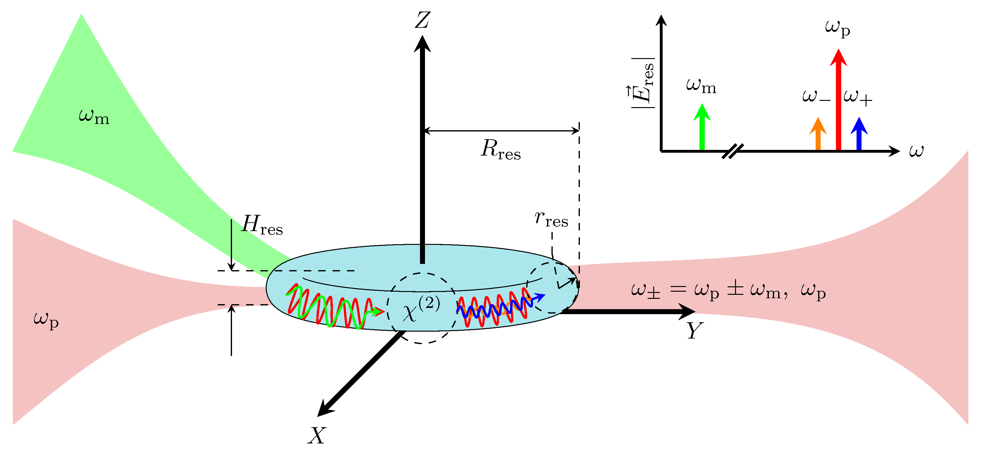
Abstract
:1. Introduction
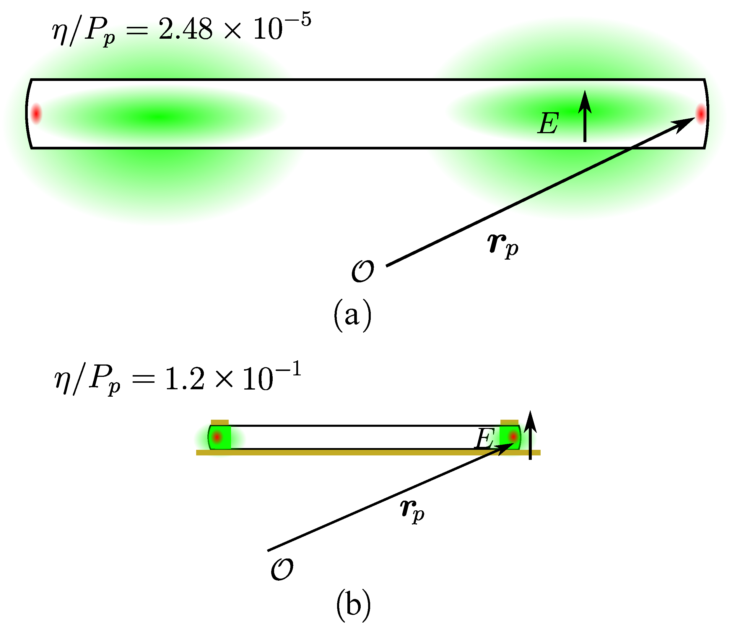
2. Enhancement of the Upconversion Photon Conversion Efficiency
3. Proposed Upconversion Scheme
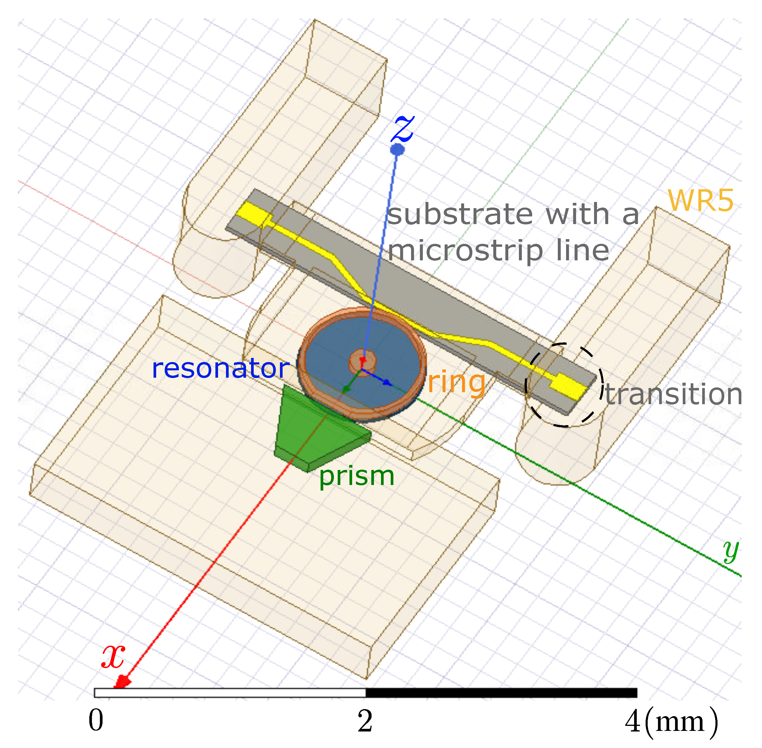
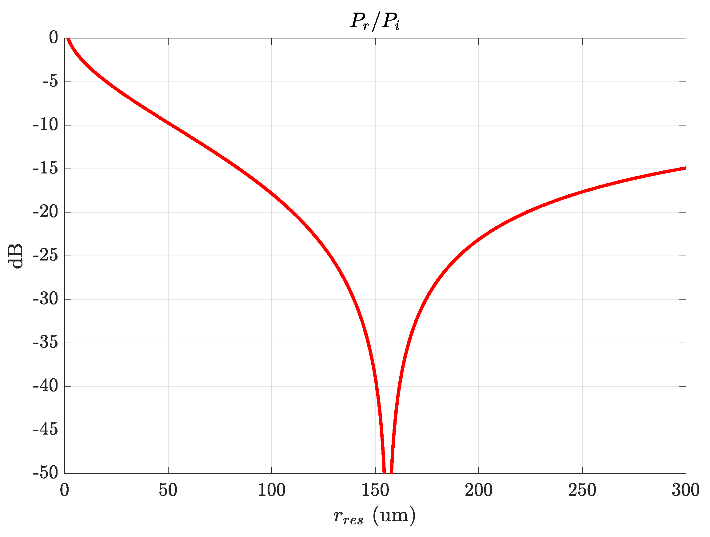
4. Integration of the Upconversion Scheme
5. Conclusions
Author Contributions
Funding
Institutional Review Board Statement
Informed Consent Statement
Data Availability Statement
Acknowledgments
Conflicts of Interest
References
- Aires, F.; Prigent, C.; Orlandi, E.; Milz, M.; Eriksson, P.; Crewell, S.; Lin, C.C.; Kangas, V. Microwave hyperspectral measurements for temperature and humidity atmospheric profiling from satellite: The clear-sky case. J. Geophys. Res. Atmos. 2015, 120, 11–334. [Google Scholar] [CrossRef] [Green Version]
- Strekalov, D.; Majurec, N.; Matsko, A.; Ilchenko, V.; Tanelli, S.; Ahmed, R. W-Band Photonic Receiver for Compact Cloud Radars. Sensors 2022, 22, 804. [Google Scholar] [CrossRef] [PubMed]
- Linder, M.; Rando, N.; Peacock, A.; Collaudin, B. Cryogenics in space—A review of the missions and technologies. ESA Bull. 2001, 107, 92–105. [Google Scholar]
- Munoz, L.E.G.; Botello, G.S.; Abdalmalak, K.; Wasiak, M. Room temperature radiometer based on an up conversion process for CubeSats applications. In Terahertz Photonics; Jarrahi, M., Preu, S., Turchinovich, D., Eds.; International Society for Optics and Photonics, SPIE: Bellingham, WA, USA, 2020; Volume 11348, pp. 27–34. [Google Scholar] [CrossRef]
- Abdalmalak, K.A.; Santamaría Botello, G.; Llorente-Romano, S.; Rivera-Lavado, A.; Flygare, J.; López Fernándezs, J.A.; Serna Puente, J.M.; García-Castillo, L.E.; Segovia-Vargas, D.; Pantaleev, M.; et al. Ultrawideband Conical Log-Spiral Circularly Polarized Feed for Radio Astronomy. IEEE Trans. Antennas Propag. 2020, 68, 1995–2007. [Google Scholar] [CrossRef]
- Wasiak, M.; Botello, G.S.; Abdalmalak, K.A.; Sedlmeir, F.; Rueda, A.; Segovia-Vargas, D.; Schwefel, H.G.L.; Muñoz, L.E.G. Compact Millimeter and Submillimeter-Wave Photonic Radiometer for Cubesats. In Proceedings of the 2020 14th European Conference on Antennas and Propagation (EuCAP), Copenhagen, Denmark, 15–20 March 2020; pp. 1–5. [Google Scholar] [CrossRef]
- Kim, B.; Yang, H. Temperature Sensor Assisted Lifetime Enhancement of Satellite Embedded Systems via Multi-Core Task Mapping and DVFS. Sensors 2019, 19, 4902. [Google Scholar] [CrossRef] [PubMed] [Green Version]
- Rueda, A.; Sedlmeir, F.; Collodo, M.C.; Vogl, U.; Stiller, B.; Schunk, G.; Strekalov, D.V.; Marquardt, C.; Fink, J.M.; Painter, O.; et al. Efficient microwave to optical photon conversion: An electro-optical realization. Optica 2016, 3, 597–604. [Google Scholar] [CrossRef]
- Lambert, N.J.; Rueda, A.; Sedlmeir, F.; Schwefel, H.G.L. Coherent Conversion between Microwave and Optical Photons—An Overview of Physical Implementations. Adv. Quantum Technol. 2020, 3, 1900077. [Google Scholar] [CrossRef] [Green Version]
- Strekalov, D.V.; Savchenkov, A.A.; Matsko, A.B.; Yu, N. Efficient upconversion of subterahertz radiation in a high-Q whispering gallery resonator. Opt. Lett. 2009, 34, 713–715. [Google Scholar] [CrossRef] [Green Version]
- Strekalov, D.V.; Marquardt, C.; Matsko, A.B.; Schwefel, H.G.L.; Leuchs, G. Nonlinear and quantum optics with whispering gallery resonators. J. Opt. 2016, 18, 123002. [Google Scholar] [CrossRef] [Green Version]
- Botello, G.S.; Sedlmeir, F.; Rueda, A.; Abdalmalak, K.A.; Brown, E.R.; Leuchs, G.; Preu, S.; Segovia-Vargas, D.; Strekalov, D.V.; Muñoz, L.E.G.; et al. Sensitivity limits of millimeter-wave photonic radiometers based on efficient electro-optic upconverters. Optica 2018, 5, 1210–1219. [Google Scholar] [CrossRef]
- Garcia-Muñoz, E.; Abdalmalak, K.A.; Santamaría, G.; Rivera-Lavado, A.; Segovia-Vargas, D.; Castillo-Araníbar, P.; Dijk, F.V.; Nagatsuma, T.; Brown, E.R.; Guzman, R.C.; et al. Photonic-based integrated sources and antenna arrays for broadband wireless links in terahertz communications. Semicond. Sci. Technol. 2020, 34, 054001. [Google Scholar] [CrossRef]
- Santamaría-Botello, G.; Popovic, Z.; Abdalmalak, K.A.; Segovia-Vargas, D.; Brown, E.R.; Muñoz, L.E.G. Sensitivity and noise in THz electro-optic upconversion radiometers. Sci. Rep. 2020, 10, 9403. [Google Scholar] [CrossRef] [PubMed]
- Botello, G.S.; Abdalmalak, K.A.; Segovia-Vargas, D.; Muñoz, L.E.G. Photonic upconversion for THz radiometry. In Proceedings of the 2019 44th International Conference on Infrared, Millimeter, and Terahertz Waves (IRMMW-THz), Paris, France, 1–6 September 2019; pp. 1–2. [Google Scholar] [CrossRef]
- Botello, G.S.; Abdalmalak, K.A.; Segovia-Vargas, D.; Murk, A.; Muñoz, L.E.G. On the Comparison Between Low Noise Amplifiers and Photonic Upconverters for Millimeter and Terahertz Radiometry. In Proceedings of the 2019 30th International Symposium on Space Terahertz Technology (ISSTT), Gothenburg, Sweden, 15–17 April 2019. [Google Scholar]
- Treuttel, J.; Gatilova, L.; Maestrini, A.; Moro-Melgar, D.; Yang, F.; Tamazouzt, F.; Vacelet, T.; Jin, Y.; Cavanna, A.; Matéos, J.; et al. A 520–620-GHz Schottky Receiver Front-End for Planetary Science and Remote Sensing With 1070 K–1500 K DSB Noise Temperature at Room Temperature. IEEE Trans. Terahertz Sci. Technol. 2016, 6, 148–155. [Google Scholar] [CrossRef]
- Leong, K.M.K.H.; Mei, X.; Yoshida, W.; Liu, P.H.; Zhou, Z.; Lange, M.; Lee, L.S.; Padilla, J.G.; Zamora, A.; Gorospe, B.S.; et al. A 0.85 THz Low Noise Amplifier Using InP HEMT Transistors. IEEE Microw. Wirel. Components Lett. 2015, 25, 397–399. [Google Scholar] [CrossRef]
- Tessmann, A.; Hurm, V.; Leuther, A.; Massler, H.; Weber, R.; Kuri, M.; Riessle, M.; Stulz, H.P.; Zink, M.; Schlechtweg, M.; et al. 243 GHz low-noise amplifier MMICs and modules based on metamorphic HEMT technology. Int. J. Microw. Wirel. Technol. 2014, 6, 215–223. [Google Scholar] [CrossRef]
- Schlecht, E.; Siles, J.V.; Lee, C.; Lin, R.; Thomas, B.; Chattopadhyay, G.; Mehdi, I. Schottky Diode Based 1.2 THz Receivers Operating at Room-Temperature and Below for Planetary Atmospheric Sounding. IEEE Trans. Terahertz Sci. Technol. 2014, 4, 661–669. [Google Scholar] [CrossRef]
- Deal, W.; Zamora, A.; Leong, K.; Liu, P.; Yoshida, W.; Zhou, J.; Lange, M.; Gorospe, B.; Nguyen, K.; Mei, X. A 670 GHz Low Noise Amplifier with <10 dB Packaged Noise Figure. IEEE Microw. Wirel. Components Lett. 2016, 26, 837–839. [Google Scholar] [CrossRef]
- Hayton, D.; Treuttel, J.; Siles, J.V.; Chen, C.P.; Lin, R.; Lee, C.; Schlecht, E.; Mehdi, I. A Compact Schottky Heterodyne Receiver for 2.06 THz Neutral Oxygen [OI]. In Proceedings of the 2018 43rd International Conference on Infrared, Millimeter, and Terahertz Waves (IRMMW-THz), Nagoya, Japan, 9–14 September 2018; pp. 1–2. [Google Scholar] [CrossRef]
- Ilchenko, V.S.; Savchenkov, A.A.; Matsko, A.B.; Maleki, L. Whispering-gallery-mode electro-optic modulator and photonic microwave receiver. J. Opt. Soc. Am. B 2003, 20, 333–342. [Google Scholar] [CrossRef]
- Tsang, M. Cavity quantum electro-optics. Phys. Rev. A 2010, 81, 063837. [Google Scholar] [CrossRef] [Green Version]
- Sedlmeir, F. Crystalline Whispering Gallery Mode Resonators. Ph.D. Thesis, Friedrich-Alexander-Universität Erlangen-Nürnberg (FAU), Erlangen, Germany, 2016. [Google Scholar]
- Guha, B.; Marsault, F.; Cadiz, F.; Morgenroth, L.; Ulin, V.; Berkovitz, V.; Lemaître, A.; Gomez, C.; Amo, A.; Combrié, S.; et al. Surface-enhanced gallium arsenide photonic resonator with quality factor of 6 × 10⁶. Optica 2017, 4, 218–221. [Google Scholar] [CrossRef]
- Kuo, P.S.; Bravo-Abad, J.; Solomon, G.S. Second-harmonic generation using-quasi-phasematching in a GaAs whispering-gallery-mode microcavity. Nat. Commun. 2014, 5, 3109. [Google Scholar] [CrossRef] [PubMed] [Green Version]
- Lake, D.P.; Mitchell, M.; Jayakumar, H.; dos Santos, L.F.; Curic, D.; Barclay, P.E. Efficient telecom to visible wavelength conversion in doubly resonant gallium phosphide microdisks. Appl. Phys. Lett. 2016, 108, 031109. [Google Scholar] [CrossRef]
- Werner, C.S.; Yoshiki, W.; Herr, S.J.; Breunig, I.; Buse, K. Geometric tuning: Spectroscopy using whispering-gallery resonator frequency-synthesizers. Optica 2017, 4, 1205–1208. [Google Scholar] [CrossRef]
- Fürst, J.U.; Buse, K.; Breunig, I.; Becker, P.; Liebertz, J.; Bohatý, L. Second-harmonic generation of light at 245 nm in a lithium tetraborate whispering gallery resonator. Opt. Lett. 2015, 40, 1932–1935. [Google Scholar] [CrossRef] [PubMed]
- Ilchenko, V.S.; Savchenkov, A.A.; Byrd, J.; Solomatine, I.; Matsko, A.B.; Seidel, D.; Maleki, L. Crystal quartz optical whispering-gallery resonators. Opt. Lett. 2008, 33, 1569–1571. [Google Scholar] [CrossRef] [PubMed]
- Vukovic, N.; Healy, N.; Sparks, J.; Badding, J.; Horak, P.; Peacock, A. Tunable continuous wave emission via phase-matched second harmonic generation in a ZnSe microcylindrical resonator. Sci. Rep. 2015, 5, 11798. [Google Scholar] [CrossRef] [PubMed] [Green Version]
- Breunig, I. Three-wave mixing in whispering gallery resonators. Laser Photonics Rev. 2016, 10, 569–587. [Google Scholar] [CrossRef]
- Abdalmalak, K.A.; Santamaría-Botello, G.; Lee, C.S.; Rivera-Lavado, A.; García-Castillo, L.E.; Segovia-Vargas, D.; García-Muñoz, L.E. Microwave Radiation Coupling into a WGM Resonator for a High-Photonic-Efficiency Nonlinear Receiver. In Proceedings of the 2018 48th European Microwave Conference (EuMC), Madrid, Spain, 23–27 September 2018; pp. 781–784. [Google Scholar] [CrossRef]
- Rivera-Lavado, A.; García-Muñoz, L.E.; Lioubtchenko, D.; Preu, S.; Abdalmalak, K.A.; Santamaría-Botello, G.; Segovia-Vargas, D.; Räisänen, A.V. Planar lens–based ultra-wideband dielectric rod waveguide antenna for tunable THz and sub-THz photomixer sources. J. Infrared Millim. Terahertz Waves 2019, 40, 838–855. [Google Scholar] [CrossRef]
- Rivera-Lavado, A.; García-Muñoz, L.E.; Generalov, A.; Lioubtchenko, D.; Abdalmalak, K.A.; Llorente-Romano, S.; García-Lampérez, A.; Segovia-Vargas, D.; Räisänen, A.V. Design of a dielectric rod waveguide antenna array for millimeter waves. J. Infrared Millim. Terahertz Waves 2017, 38, 33–46. [Google Scholar] [CrossRef]
- Farnesi, D.; Righini, G.; Barucci, A.; Berneschi, S.; Chiavaioli, F.; Cosi, F.; Pelli, S.; Soria, S.; Trono, C.; Ristic, D.; et al. Coupling light to whispering gallery mode resonators. In Silicon Photonics and Photonic Integrated Circuits IV; SPIE: Bellingham, WA, USA, 2014; Volume 9133, pp. 179–187. [Google Scholar]
- Soltani, M.; Ilchenko, V.; Matsko, A.; Savchenkov, A.; Schlafer, J.; Ryan, C.; Maleki, L. Ultrahigh Q whispering gallery mode electro-optic resonators on a silicon photonic chip. Opt. Lett. 2016, 41, 4375–4378. [Google Scholar] [CrossRef]
- Farnesi, D.; Pelli, S.; Soria, S.; Conti, G.N.; Roux, X.L.; Ballester, M.M.; Vivien, L.; Cheben, P.; Alonso-Ramos, C. Metamaterial engineered silicon photonic coupler for whispering gallery mode microsphere and disk resonators. Optica 2021, 8, 1511–1514. [Google Scholar] [CrossRef]
- Santamaría-Botello, G.A.; Muñoz, L.E.G.; Sedlmeir, F.; Preu, S.; Segovia-Vargas, D.; Abdalmalak, K.A.; Romano, S.L.; Lampérez, A.G.; Malzer, S.; Döhler, G.H.; et al. Maximization of the optical intra-cavity power of whispering-gallery mode resonators via coupling prism. Opt. Express 2016, 24, 26503–26514. [Google Scholar] [CrossRef] [PubMed]
- Roselló-Mechó, X.; Delgado-Pinar, M.; Barmenkov, Y.O.; Kir’yanov, A.V.; Andrés, M.V. Application of WGM Resonances to the Measurement of the Temperature Increment of Ho and Ho-Yb Doped Optical Fibers Pumped at 1125 and 975 nm. Sensors 2021, 21, 2094. [Google Scholar] [CrossRef] [PubMed]


Publisher’s Note: MDPI stays neutral with regard to jurisdictional claims in published maps and institutional affiliations. |
© 2022 by the authors. Licensee MDPI, Basel, Switzerland. This article is an open access article distributed under the terms and conditions of the Creative Commons Attribution (CC BY) license (https://creativecommons.org/licenses/by/4.0/).
Share and Cite
Abdalmalak, K.A.; Botello, G.S.; Suresh, M.I.; Falcón-Gómez, E.; Lavado, A.R.; García-Muñoz, L.E. An Integrated Millimeter-Wave Satellite Radiometer Working at Room-Temperature with High Photon Conversion Efficiency. Sensors 2022, 22, 2400. https://doi.org/10.3390/s22062400
Abdalmalak KA, Botello GS, Suresh MI, Falcón-Gómez E, Lavado AR, García-Muñoz LE. An Integrated Millimeter-Wave Satellite Radiometer Working at Room-Temperature with High Photon Conversion Efficiency. Sensors. 2022; 22(6):2400. https://doi.org/10.3390/s22062400
Chicago/Turabian StyleAbdalmalak, Kerlos Atia, Gabriel Santamaria Botello, Mallika Irene Suresh, Enderson Falcón-Gómez, Alejandro Rivera Lavado, and Luis Enrique García-Muñoz. 2022. "An Integrated Millimeter-Wave Satellite Radiometer Working at Room-Temperature with High Photon Conversion Efficiency" Sensors 22, no. 6: 2400. https://doi.org/10.3390/s22062400
APA StyleAbdalmalak, K. A., Botello, G. S., Suresh, M. I., Falcón-Gómez, E., Lavado, A. R., & García-Muñoz, L. E. (2022). An Integrated Millimeter-Wave Satellite Radiometer Working at Room-Temperature with High Photon Conversion Efficiency. Sensors, 22(6), 2400. https://doi.org/10.3390/s22062400