
Intelligent Reflecting Surfaces Beamforming Optimization with Statistical Channel Knowledge

 ,
,  , and
, and
Abstract
:1. Introduction
Contributions
- 1.
- We develop a novel framework based on meta-heuristic methods to design beamforming at BS and IRS without requiring I-CSI;
- 2.
- We reveal that the proposed solution can achieve a close-to-ideal performance by considering only S-CSI knowledge with low training overhead.
2. System Model
Optimization Problem
3. Genetic Algorithms
- 1.
- Randomly generate the individuals of the first generation;
- 2.
- Compute the fitness of each individual;
- 3.
- Elitism: Create a set with some of the fittest individuals of the current generation and perpetuate these individuals to the next generation;
- 4.
- Select some individuals (named parents) by the Tournament Method (Selection Method), which will be submitted to the Reproduction Process (Crossover and Mutation Operators).
- 5.
- Crossover Operator: This operator makes the permutation of the genetic material of the selected parents and generates children with probability , generating a set of new individuals.
- 6.
- Mutation Operator: The individuals generated in the previous step are submitted to the Mutation Operator with probability , generating another set of individuals.
- 7.
- Generate the new population by the union of the sets of individuals generated in Steps 3 and 6.
- 8.
- The GA is completed if the stop criterion is fulfilled. Otherwise, return to Step 2.
3.1. Selection Method
3.2. Reproduction Process
3.2.1. Crossover Operator
3.2.2. Mutation Operator
3.3. Elitism
4. Proposed Solution
- 1.
- 2.
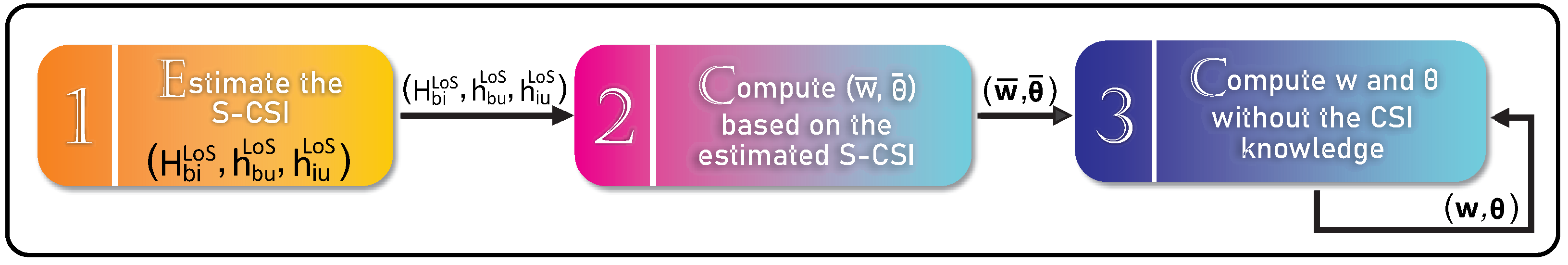
- Compute and : Based on the estimated S-CSI, in this phase, we consider Algorithm 1 to compute and . To better explain the operation of Algorithm 1, its main steps are described as follows:
- I.
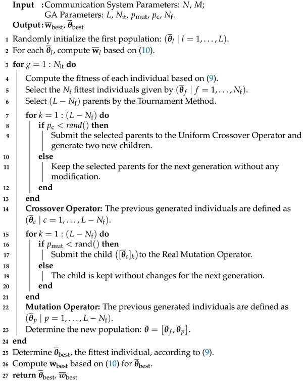
- Randomly generate L beamforming vectors at the IRS . For each , compute the Maximum-Ratio Transmission (MRT) beamforming vector [47] given by the following:where it is important to highlight that, for a given , is the optimal transmit beamforming at the BS considering only S-CSI. Here, each individual in the proposed GA is defined as a beamforming vector at the IRS .
- II.
- Calculate the fitness defined by (7) of each individual, where SNR at UE is given by the following:where .
- III.
- Elitism: Select the fittest individuals , which are preserved without any modification for the next generation.
- IV.
- Selection Process: Select, from the Tournament Method, parents from the individuals of the current generation.
- V.
- Crossover Operator: With crossover probability , generate children from the crossing of the selected parents. Otherwise, with probability , the children are the same as the selected parents. The following individuals are generated: .
- VI.
- Mutation Operator: With mutation probability , select one child generated in Step V and submit it to the Real Mutation Operator. Otherwise, the selected child is perpetuated for the next generation. This step is run times. The following individuals are generated .
- VII.
- The new population is generated by the union of the individuals generated in Steps III and VI . In other words, the L beamforming vectors, , are updated.
- VIII.
- Check whether the maximum number of iterations has been reached (stop criterion). If so, return the fittest individual . Otherwise, proceed to Step II.
- 3.
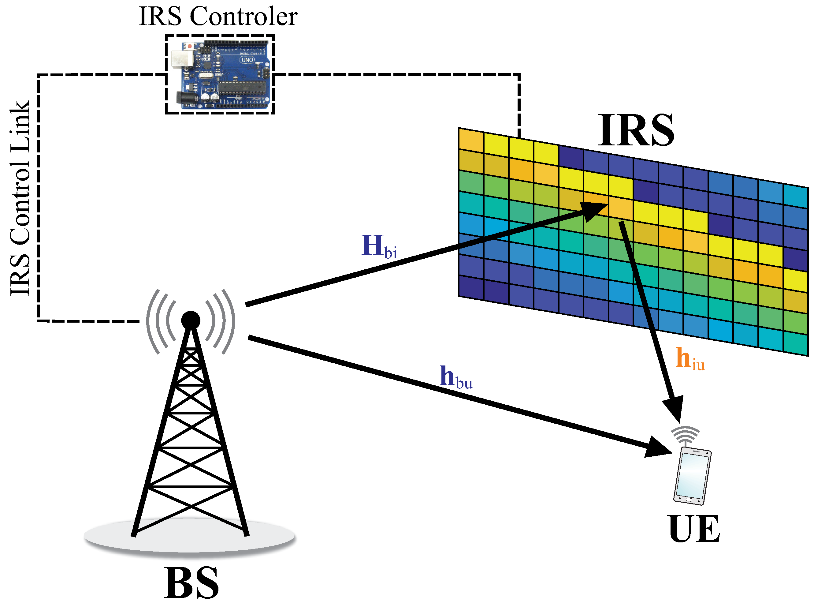
- Compute w and : In this phase, the beamforming vectors at BS and the phase shifts at the IRS to be tested are defined at BS and sent to IRS from the controller illustrated in Figure 1. For each beamforming pair, the BS receives feedback of the SNR at UE, and the beamforming pair is evaluated based on (7). This process is repeated for all pairs. In addition, in order to speed up the convergence of the proposed solution and to reduce overhead since we assume a limited mobility scenario, in the process of generating the first population of the proposed method, as illustrated in Figure 2, we consider the knowledge of both beamforming pairs based on S-CSI computed in Phase 2 and the best pair of beamforming computed in the previous channel realization. Note that, in this approach, I-CSI does not need to be estimated. Therefore, we do not need to equip IRS with several RF chains and we do not require any explicit channel estimation processes. The proposed solution is detailed in Algorithm 2, and its main steps are described next.
- I.
- The first population is generated by the following individuals: (i) () pairs of beamforming (individuals) randomly generated; (ii) the beamforming pair generated in the first phase considering S-CSI; and (iii) the best beamforming pair from the previous channel realization .
- II.
- III.
- Elitism: Select the fittest individuals , which are maintained for the next generation.
- IV.
- Selection Process: Select individuals from the individuals of the current generation.
- V.
- Crossover Operator: With probability , generate children from the crossing of the selected parents. Otherwise, with probability , the children are the selected parents without any modification. The generated individuals are stored in .
- VI.
- Mutation Operator: With mutation probability , randomly select an individual selected in Step III. Otherwise, with probability , randomly select an individual generated in Step V. In either case, submit the selected individual to the Real Mutation Operator with probability . This step must be run times, and the following individuals are generated .
- VII.
- The new population is generated by the union of individuals generated in Steps III, V, and VI, .
- VIII.
- Check if the maximum number of iterations is reached (stop criterion). If so, then return the fittest individual . Otherwise, proceed to Step II.
| Algorithm 1: Algorithm applied in Phase 2 to compute , . |
 |
| Algorithm 2: Algorithm applied in Phase 3 to compute . |
 |
5. Simulation Results
5.1. Number of Phase Bits
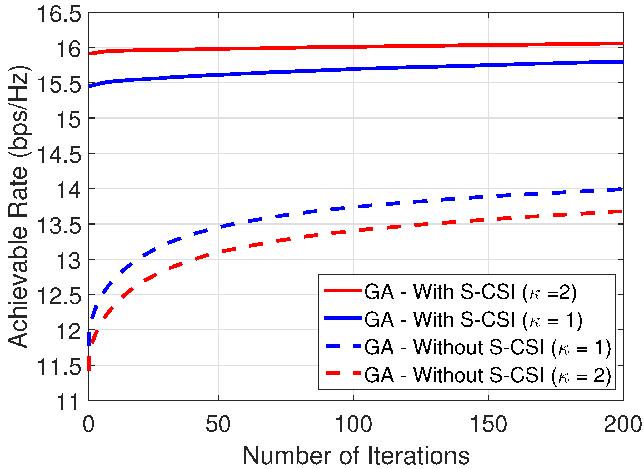
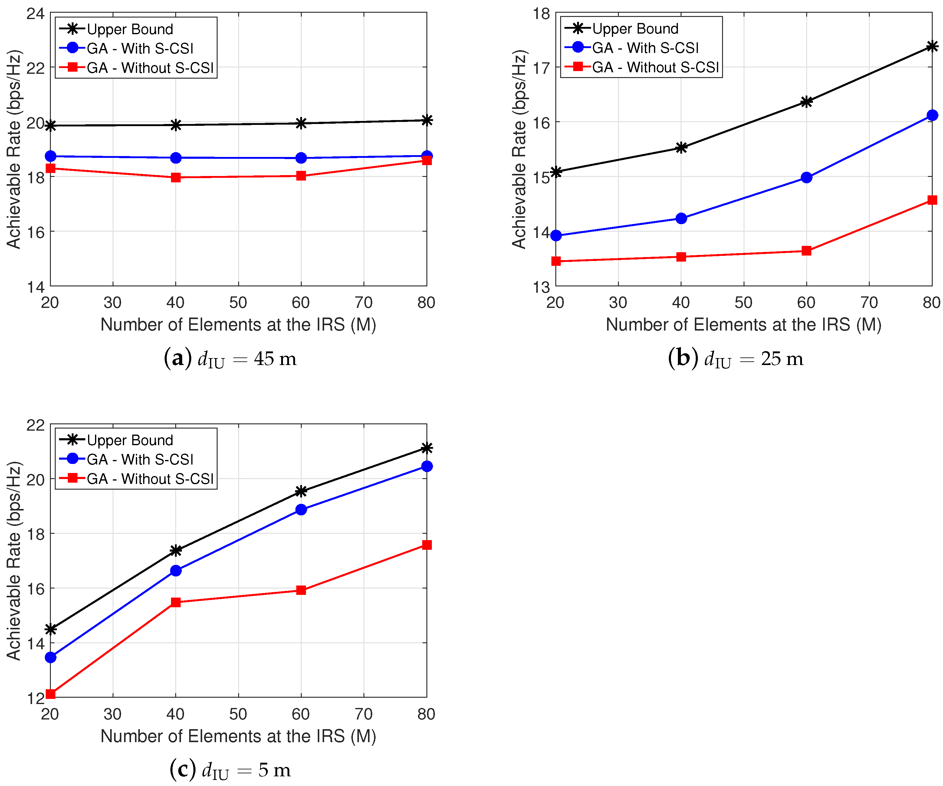
5.2. Influence of LoS and Topology
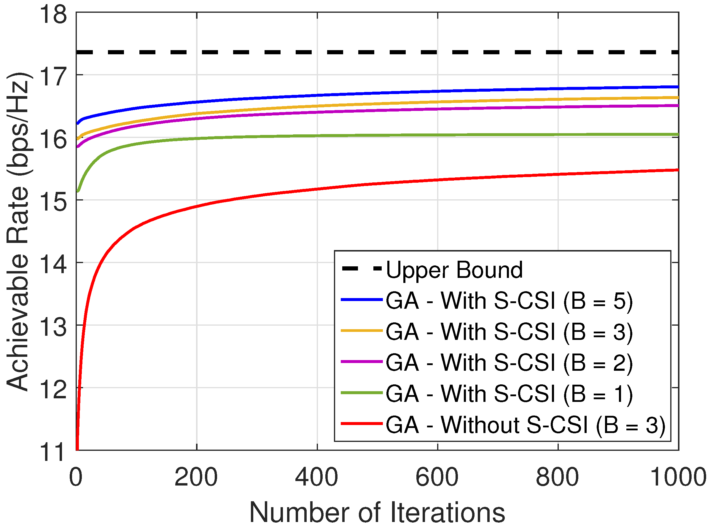
5.3. Amount of Feedback
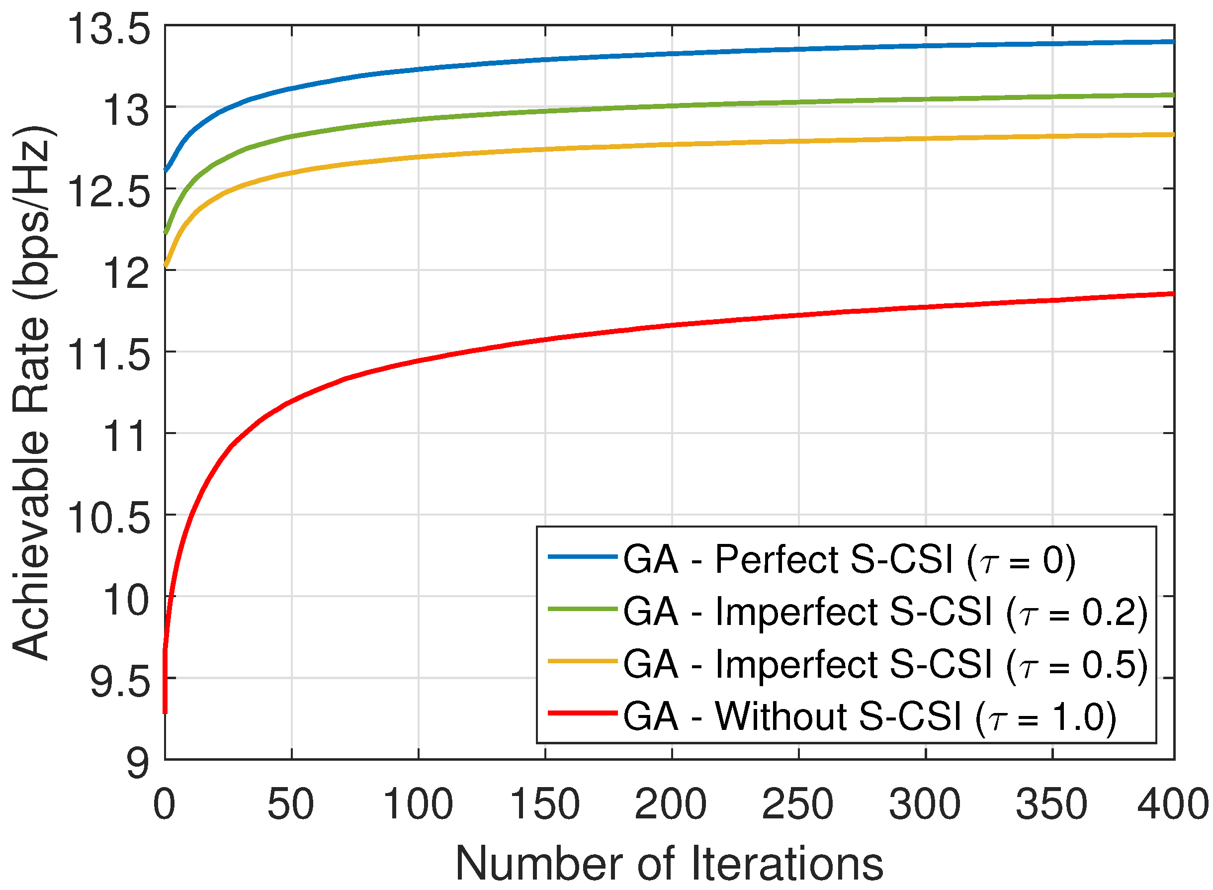
5.4. Imperfect S-CSI Knowledge
5.5. Computational Complexity
6. Conclusions
Author Contributions
Funding
Institutional Review Board Statement
Informed Consent Statement
Data Availability Statement
Conflicts of Interest
Abbreviations
| BS | Base Station |
| CSI | Channel State Information |
| GA | Genetic Algorithm |
| I-CSI | Instantaneous CSI |
| IRS | Intelligent Reflecting Surfaces |
| LoS | Line-of-Sight |
| NLoS | Non-LoS |
| MIMO | Multiple-Input Multiple-Output |
| MISO | Multiple-Input Single-Output |
| mMIMO | massive MIMO |
| MRC | Maximum Ratio Combining |
| PSO | Particle Swarm Optimization |
| S-CSI | Statistical CSI |
| SNR | Signal-to-Noise Ration |
| UE | User Equipment |
| ULA | Uniform Linear Array |
| UPA | Uniform Planar Array |
| Constant path loss factors. | |
| Pathloss of the BS-UE link | |
| Pathloss of the BS-IRS-UE link | |
| Phase shift vector at the IRS | |
| Phase shift vector at the IRS considering only S-CSI | |
| Elevation angles | |
| Rician factor for all links | |
| Wavelength | |
| Amplitude reflection coefficient | |
| Power noise | |
| Estimation accuracy | |
| Random phase in the LoS components of the BS-IRS link | |
| Random phase in the LoS components of the BS-UE link | |
| Random phase in the LoS components of the IRS-UE link | |
| Azimuth angle | |
| B | Number of bits per each element at the IRS |
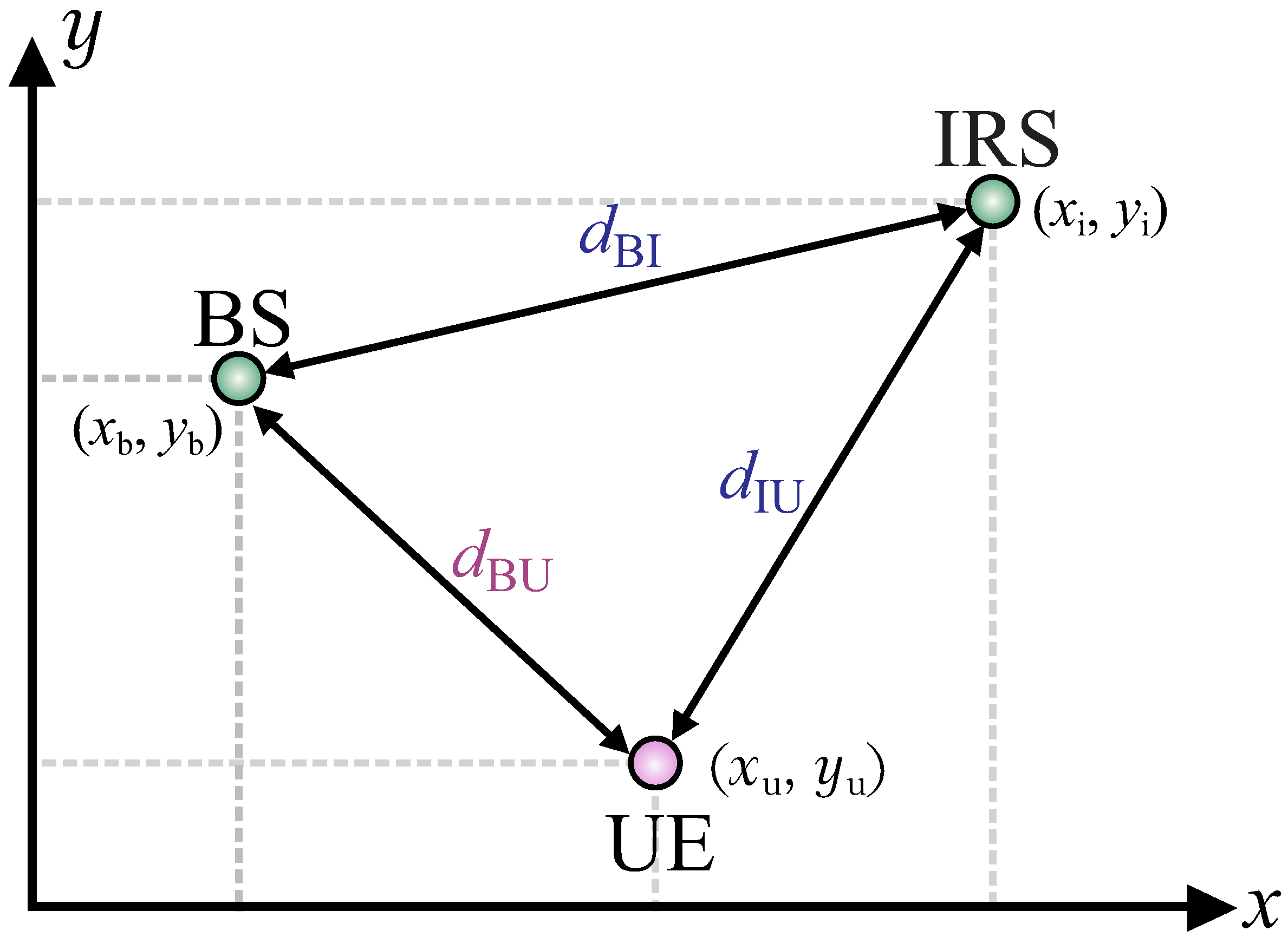
| BS-IRS link distance | |
| Distance among the BS elements | |
| BS-UE link distance | |
| Distance among the IRS elements | |
| IRS-UE link distance | |
| Estimation error | |
| Antenna gain at the UE | |
| Antenna gain at the BS | |
| BS-UE channel vector | |
| Deterministic LoS components of the BS-UE link | |
| Rayleigh fading of the BS-UE link | |
| IRS-UE channel vector | |
| Deterministic LoS components of the IRS-UE link | |
| Rayleigh fading of the IRS-UE link | |
| BS-IRS channel matrix | |
| Deterministic LoS components of the BS-IRS link | |
| Imperfect estimation of the LoS components of the BS-IRS link | |
| K | Phase shift levels |
| L | GA population size |
| M | Number of elements at the IRS |
| Number of elements in the horizontal level at the IRS | |
| Number of elements in the vertical level at the IRS | |
| n | Additive white Gaussian noise at the UE |
| N | Number of antennas at the BS |
| Number of iterations at the GA | |
| Number of elements selected by the elitism process | |
| Crossover probability | |
| Mutation probability | |
| Transmit power at the BS | |
| Achievable rate at the UE | |
| s | Transmitted data |
| Set of all possible discrete phases at the IRS | |
| Number of elements selected to compete in a tournament. | |
| Beamforming vector at the BS | |
| Beamforming vector at the BS considering only S-CSI | |
| BS position | |
| IRS position | |
| UE position | |
| y | Received signal at the IRS |
References
- Özdoğan, Ö.; Björnson, E. Deep Learning-based Phase Reconfiguration for Intelligent Reflecting Surfaces. In Proceedings of the 2020 54th Asilomar Conference on Signals, Systems, and Computers, Pacific Grove, CA, USA, 1–5 November 2020; pp. 707–711. [Google Scholar] [CrossRef]
- Liaskos, C.; Nie, S.; Tsioliaridou, A.; Pitsillides, A.; Ioannidis, S.; Akyildiz, I. A New Wireless Communication Paradigm through Software-Controlled Metasurfaces. IEEE Commun. Mag. 2018, 56, 162–169. [Google Scholar] [CrossRef] [Green Version]
- Wu, Q.; Zhang, R. Beamforming Optimization for Intelligent Reflecting Surface with Discrete Phase Shifts. In Proceedings of the ICASSP 2019—2019 IEEE International Conference on Acoustics, Speech and Signal Processing (ICASSP), Brighton, UK, 12–17 May 2019; pp. 7830–7833. [Google Scholar]
- Wu, Q.; Zhang, R. Towards Smart and Reconfigurable Environment: Intelligent Reflecting Surface Aided Wireless Network. IEEE Commun. Mag. 2020, 58, 106–112. [Google Scholar] [CrossRef] [Green Version]
- Huang, C.; Zappone, A.; Alexandropoulos, G.C.; Debbah, M.; Yuen, C. Reconfigurable Intelligent Surfaces for Energy Efficiency in Wireless Communication. IEEE Trans. Wirel. Commun. 2019, 18, 4157–4170. [Google Scholar] [CrossRef] [Green Version]
- Di Renzo, M.; Zappone, A.; Debbah, M.; Alouini, M.S.; Yuen, C.; de Rosny, J.; Tretyakov, S. Smart Radio Environments Empowered by Reconfigurable Intelligent Surfaces: How It Works, State of Research, and The Road Ahead. IEEE J. Sel. Areas Commun. 2020, 38, 2450–2525. [Google Scholar] [CrossRef]
- Souto, V.D.P.; Souza, R.D.; Uchôa-Filho, B.F.; Li, A.; Li, Y. Beamforming Optimization for Intelligent Reflecting Surfaces without CSI. IEEE Wirel. Commun. Lett. 2020, 9, 1476–1480. [Google Scholar] [CrossRef]
- Wu, Q.; Zhang, R. Intelligent Reflecting Surface Enhanced Wireless Network: Joint Active and Passive Beamforming Design. In Proceedings of the 2018 IEEE Global Communications Conference (GLOBECOM), Abu Dhabi, UAE, 9–13 December 2018; pp. 1–6. [Google Scholar] [CrossRef] [Green Version]
- Wu, Q.; Zhang, R. Intelligent Reflecting Surface Enhanced Wireless Network via Joint Active and Passive Beamforming. IEEE Trans. Wirel. Commun. 2019, 18, 5394–5409. [Google Scholar] [CrossRef] [Green Version]
- Yang, Y.; Zhang, S.; Zhang, R. IRS-Enhanced OFDM: Power Allocation and Passive Array Optimization. In Proceedings of the 2019 IEEE Global Communications Conference (GLOBECOM), Waikoloa, HI, USA, 9–13 December 2019; pp. 1–6. [Google Scholar]
- Wu, Q.; Zhang, R. Beamforming Optimization for Wireless Network Aided by Intelligent Reflecting Surface with Discrete Phase Shifts. IEEE Trans. Commun. 2019, 68, 1838–1851. [Google Scholar] [CrossRef] [Green Version]
- Abeywickrama, S.; Zhang, R.; Wu, Q.; Yuen, C. Intelligent Reflecting Surface: Practical Phase Shift Model and Beamforming Optimization. IEEE Trans. Commun. 2020, 68, 5849–5863. [Google Scholar] [CrossRef]
- Guo, H.; Liang, Y.; Chen, J.; Larsson, E.G. Weighted Sum-Rate Maximization for Intelligent Reflecting Surface Enhanced Wireless Networks. In Proceedings of the 2019 IEEE Global Communications Conference (GLOBECOM), Waikoloa, HI, USA, 9–13 December 2019; pp. 1–6. [Google Scholar] [CrossRef]
- Di, B.; Zhang, H.; Song, L.; Li, Y.; Han, Z.; Poor, H.V. Hybrid Beamforming for Reconfigurable Intelligent Surface based Multi-User Communications: Achievable Rates With Limited Discrete Phase Shifts. IEEE J. Sel. Areas Commun. 2020, 38, 1809–1822. [Google Scholar] [CrossRef]
- Zhang, J.; Liu, J.; Ma, S.; Wen, C.; Jin, S. Transmitter Design for Large Intelligent Surface-Assisted MIMO Wireless Communication with Statistical CSI. In Proceedings of the 2020 IEEE International Conference on Communications Workshops (ICC Workshops), Dublin, Ireland, 7–11 June 2020; pp. 1–5. [Google Scholar] [CrossRef]
- Han, Y.; Tang, W.; Jin, S.; Wen, C.; Ma, X. Large Intelligent Surface-Assisted Wireless Communication Exploiting Statistical CSI. IEEE Trans. Veh. Technol. 2019, 68, 8238–8242. [Google Scholar] [CrossRef] [Green Version]
- Zhang, J.; Liu, J.; Ma, S.; Wen, C.K.; Jin, S. Large System Achievable Rate Analysis of RIS-Assisted MIMO Wireless Communication with Statistical CSIT. IEEE Trans. Wirel. Commun. 2021, 20, 5572–5585. [Google Scholar] [CrossRef]
- Abrardo, A.; Dardari, D.; Di Renzo, M. Intelligent Reflecting Surfaces: Sum-Rate Optimization Based on Statistical Position Information. IEEE Trans. Commun. 2021, 69, 7121–7136. [Google Scholar] [CrossRef]
- Gan, X.; Zhong, C.; Huang, C.; Zhang, Z. RIS-Assisted Multi-User MISO Communications Exploiting Statistical CSI. IEEE Trans. Commun. 2021, 69, 6781–6792. [Google Scholar] [CrossRef]
- Zhao, M.M.; Wu, Q.; Zhao, M.J.; Zhang, R. Intelligent Reflecting Surface Enhanced Wireless Network: Two-Timescale Beamforming Optimization. IEEE Trans. Wirel. Commun. 2020, 20, 2–17. [Google Scholar] [CrossRef]
- Zhao, M.; Wu, Q.; Zhao, M.; Zhang, R. Two-timescale Beamforming Optimization for Intelligent Reflecting Surface Enhanced Wireless Network. In Proceedings of the 2020 IEEE 11th Sensor Array and Multichannel Signal Processing Workshop (SAM), Hangzhou, China, 8–11 June 2020; pp. 1–5. [Google Scholar] [CrossRef]
- Zhao, M.M.; Liu, A.; Wan, Y.; Zhang, R. Two-timescale Beamforming Optimization for Intelligent Reflecting Surface Aided Multiuser Communication with QoS Constraints. IEEE Trans. Wirel. Commun. 2021, 20, 6179–6194. [Google Scholar] [CrossRef]
- Peng, Z.; Li, T.; Pan, C.; Ren, H.; Xu, W.; Renzo, M.D. Analysis and Optimization for RIS-Aided Multi-Pair Communications Relying on Statistical CSI. IEEE Trans. Veh. Technol. 2021, 70, 3897–3901. [Google Scholar] [CrossRef]
- Zhi, K.; Pan, C.; Ren, H.; Wang, K. Power Scaling Law Analysis and Phase Shift Optimization of RIS-aided Massive MIMO Systems with Statistical CSI. arXiv 2021, arXiv:2010.13525. [Google Scholar]
- Zhi, K.; Pan, C.; Ren, H.; Wang, K. Statistical CSI-Based Design for Reconfigurable Intelligent Surface-Aided Massive MIMO Systems With Direct Links. IEEE Wirel. Commun. Lett. 2021, 10, 1128–1132. [Google Scholar] [CrossRef]
- Nadeem, Q.U.A.; Zappone, A.; Chaaban, A. Intelligent Reflecting Surface Enabled Random Rotations Scheme for the MISO Broadcast Channel. IEEE Trans. Wirel. Commun. 2021, 20, 5226–5242. [Google Scholar] [CrossRef]
- Jamali, V.; Alexandropoulos, G.C.; Schober, R.; Poor, H.V. Low-to-Zero-Overhead IRS Reconfiguration: Decoupling Illumination and Channel Estimation. IEEE Commun. Lett. 2021. [Google Scholar] [CrossRef]
- Psomas, C.; Krikidis, I. Low-Complexity Random Rotation-Based Schemes for Intelligent Reflecting Surfaces. IEEE Trans. Wirel. Commun. 2021, 20, 5212–5225. [Google Scholar] [CrossRef]
- Sangaiah, A.K.; Zhang, Z.; Sheng, M. Computational Intelligence for Multimedia Big Data on the Cloud with Engineering Applications; Elsevier Science: Amsterdam, The Netherlands, 2018. [Google Scholar] [CrossRef]
- Pham, Q.V.; Nguyen, D.C.; Mirjalili, S.; Hoang, D.T.; Nguyen, D.N.; Pathirana, P.N.; Hwang, W.J. Swarm Intelligence for Next-Generation Wireless Networks: Recent Advances and Applications. arXiv 2020, arXiv:2007.15221. [Google Scholar]
- Zheng, B.; Wu, Q.; Zhang, R. Intelligent Reflecting Surface-Assisted Multiple Access with User Pairing: NOMA or OMA? IEEE Commun. Lett. 2020, 24, 753–757. [Google Scholar] [CrossRef] [Green Version]
- Further Advancements for E-UTRA Physical Layer Aspects (Release 9); Technical Report, 3GPP. 2010. Available online: https://www.3gpp.org/ftp/Specs/archive/36_series/36.814/ (accessed on 18 January 2022).
- Ozdogan, O.; Bjornson, E.; Larsson, E.G. Using Intelligent Reflecting Surfaces for Rank Improvement in MIMO Communications. In Proceedings of the ICASSP 2020—2020 IEEE International Conference on Acoustics, Speech and Signal Processing (ICASSP), Barcelona, Spain, 4–8 May 2020; pp. 9160–9164. [Google Scholar] [CrossRef] [Green Version]
- Cheng, Y.; Li, K.H.; Liu, Y.; Teh, K.C.; Vincent Poor, H. Downlink and Uplink Intelligent Reflecting Surface Aided Networks: NOMA and OMA. IEEE Trans. Wirel. Commun. 2021, 20, 3988–4000. [Google Scholar] [CrossRef]
- Zeng, M.; Li, X.; Li, G.; Hao, W.; Dobre, O.A. Sum Rate Maximization for IRS-Assisted Uplink NOMA. IEEE Commun. Lett. 2021, 25, 234–238. [Google Scholar] [CrossRef]
- Ding, Z.; Vincent Poor, H. A Simple Design of IRS-NOMA Transmission. IEEE Commun. Lett. 2020, 24, 1119–1123. [Google Scholar] [CrossRef] [Green Version]
- Li, Z.; Chen, W.; Wu, Q.; Wang, K.; Li, J. Joint Beamforming Design and Power Splitting Optimization in IRS-Assisted SWIPT NOMA Networks. IEEE Trans. Wirel. Commun. 2021, 21, 2019–2033. [Google Scholar] [CrossRef]
- Björnson, E.; Sanguinetti, L. Rayleigh Fading Modeling and Channel Hardening for Reconfigurable Intelligent Surfaces. IEEE Wirel. Commun. Lett. 2021, 10, 830–834. [Google Scholar] [CrossRef]
- Darwin, C.A. The Origin of Species; Collins Classics; William Collins: London, UK, 2011. [Google Scholar]
- Souto, V.D.P.; Souza, R.D.; Uchôa-Filho, B.F.; Li, Y. A Novel Efficient Initial Access Method for 5G Millimeter Wave Communications Using Genetic Algorithm. IEEE Trans. Veh. Technol. 2019, 68, 9908–9919. [Google Scholar] [CrossRef]
- Mitchell, M. An Introduction to Genetic Algorithms; MIT Press: Cambridge, MA, USA, 1998. [Google Scholar]
- Sivanandam, S.; Deepa, S.N. Introduction to Genetic Algorithms; Springer: Berlin/Heidelberg, Germany, 2008; Volume 1. [Google Scholar]
- Goldberg, D.R. Genetic Algorithms in Search, Optimization, and Machine Learning; Addison Wesley Longman Inc.: New York, NY, USA, 1989. [Google Scholar]
- Gen, M.; Cheng, R. Genetic Algorithms and Engineering Optimization; John Wiley & Sons Inc.: Hoboken, NJ, USA, 1999; Volume 1. [Google Scholar]
- Mestre, X. Improved Estimation of Eigenvalues and Eigenvectors of Covariance Matrices Using Their Sample Estimates. IEEE Trans. Inf. Theory 2008, 54, 5113–5129. [Google Scholar] [CrossRef]
- Werner, K.; Jansson, M.; Stoica, P. On Estimation of Covariance Matrices with Kronecker Product Structure. IEEE Trans. Signal Process. 2008, 56, 478–491. [Google Scholar] [CrossRef]
- Lo, T.K.Y. Maximum ratio transmission. IEEE Trans. Commun. 1999, 47, 1458–1461. [Google Scholar] [CrossRef]
- Grant, M.; Boyd, S. CVX: Matlab Software for Disciplined Convex Programming; Version 2.2. 2020. Available online: http://cvxr.com/cvx/ (accessed on 18 January 2022).
- You, C.; Zheng, B.; Zhang, R. Channel Estimation and Passive Beamforming for Intelligent Reflecting Surface: Discrete Phase Shift and Progressive Refinement. IEEE J. Sel. Areas Commun. 2020, 38, 2604–2620. [Google Scholar] [CrossRef]
- Zappone, A.; Di Renzo, M.; Shams, F.; Qian, X.; Debbah, M. Overhead-Aware Design of Reconfigurable Intelligent Surfaces in Smart Radio Environments. IEEE Trans. Wirel. Commun. 2021, 20, 126–141. [Google Scholar] [CrossRef]
- Nosrat-Makouei, B.; Andrews, J.G.; Heath, R.W. MIMO Interference Alignment Over Correlated Channels with Imperfect CSI. IEEE Trans. Signal Process. 2011, 59, 2783–2794. [Google Scholar] [CrossRef] [Green Version]


| GA Parameter | Meaning |
|---|---|
| Gene | An element of the beamforming vector |
| Individual | The set of optimization variables in the problem |
| Population | A set of solutions for the optimization problem |
| Parents | Individuals selected in the Selection Method |
| Children | Individual generated by the Crossover Operator |
| Fitness Function | Metric defined by the optimization problem |
| Fitness | Output of the fitness function |
| Generation | Iteration of the algorithm |
| Parameter | Value |
|---|---|
| N | 10 |
| 10 | |
| 2 | |
| 2 | |
| 8% (case with S-CSI) | |
| 5% (case without S-CSI) | |
| 90% (for both cases) | |
| 0.5 | |
| 3 dBi | |
| 3 dBi | |
| 4 GHz | |
| 1 (if not specified otherwise) | |
| (50, 10) m | |
| (100, 10) m | |
| [9] | dBm |
| 20 dBm | |
| 41.98 | |
| 21.98 |
Publisher’s Note: MDPI stays neutral with regard to jurisdictional claims in published maps and institutional affiliations. |
© 2022 by the authors. Licensee MDPI, Basel, Switzerland. This article is an open access article distributed under the terms and conditions of the Creative Commons Attribution (CC BY) license (https://creativecommons.org/licenses/by/4.0/).
Share and Cite
Souto, V.D.P.; Souza, R.D.; Uchôa-Filho, B.F.; Li, Y. Intelligent Reflecting Surfaces Beamforming Optimization with Statistical Channel Knowledge. Sensors 2022, 22, 2390. https://doi.org/10.3390/s22062390
Souto VDP, Souza RD, Uchôa-Filho BF, Li Y. Intelligent Reflecting Surfaces Beamforming Optimization with Statistical Channel Knowledge. Sensors. 2022; 22(6):2390. https://doi.org/10.3390/s22062390
Chicago/Turabian StyleSouto, Victoria Dala Pegorara, Richard Demo Souza, Bartolomeu F. Uchôa-Filho, and Yonghui Li. 2022. "Intelligent Reflecting Surfaces Beamforming Optimization with Statistical Channel Knowledge" Sensors 22, no. 6: 2390. https://doi.org/10.3390/s22062390
APA StyleSouto, V. D. P., Souza, R. D., Uchôa-Filho, B. F., & Li, Y. (2022). Intelligent Reflecting Surfaces Beamforming Optimization with Statistical Channel Knowledge. Sensors, 22(6), 2390. https://doi.org/10.3390/s22062390